Messsystem zur fernmessung von strom und spannung in elektroenergienetzen
The invention concerns a measuring system for the telemetering of the tension arising in a far net place and/or the river flowing there, whereby between a close measuring point and the far net place a net impedance built up from at least a transformer and a passive connecting net is present.
Well-known measuring systems for telemetering in electricity mains find different execution forms application in many. In US a mechanism is descriptive 5,352,983 A for the detection of an estimate between lines in nets with different tension levels, whereby the one line is formed by a high voltage transmission line and the other line over a transformer with well-known speed ratio and well-known impedance is attached to the high voltage transmission line. The fault current caused by the estimate is equated a detected current change in any of the phases of the high voltage transmission line. With the help of this acceptance the relative distance can be determined to the defective equipment with well-known line impedance. The current change must be determined however on the high voltage side, what from disadvantage is if the high voltage side is not only with difficulty accessible or.
From the FR 2,671,635 A further a system follows for the fault current analysis on HochspannungsFreileitungen, with which in each phase conductor a ring transformer is intended, over which a tension proportional to the flowing river is produced, which is passed on by means of a sensor and over a radio link to a central measuring station. From the comparison the three phase stream appropriate tensions the occurrence of a fault current can be determined. The quality of the river or the tension at a distant point cannot be determined with this method however.
In the EP 0,334,310 A a procedure for the detection of an error between two points is shown on a high voltage transmission line, whereby the impedance of the error free line between these two points admits is. The measurement of the tension at one of these two points is computed by means of capacitive tension transformers and by means of current transformers durchgef0hrt and by linear involution a spacer value and a value of the dangerous voltage at the defective equipment. The high voltage transmission line is however directly accessible and not by a transformer from the measuring point separately thereby.
Finally US reveals 4,577,254 A a protective relay system, with which the inductance of an electrical channel is computed by release of a differential equation and formed due to the computed inductance value an error signal for the release of a signal. The measuring signals Spannungsund of a current transformer are consulted thereby for the computation of inductance. The measurements accomplished thereby are made directly at a channel without transformer.
In electrical system, primarily in electrical distributed networks, local Stromund tension quality and disturbing missions by measurement and evaluation Stromund of potential gradient in three outer conductors determined, whereby the collection place agrees with the place, for which the technical statements are met. With well-known systems the evaluation of the results of measurement takes place in low-voltage systems via direct evaluation of the three outer conductor earth tensions and/or the three line-to-line voltages and - flows. In high-voltage transmission systems the tensions are judged by measurement on the secondary winding by potential transformers. Well-known mechanisms for the measurement of the parameters Stromund tension quality and the disturbing missions work on the principles:
a) Collection general Stromund of tension processes at the desired place and computation of the desired parameters.
b) Collection of the disturbing missions in a certain place in the net by evaluation of the there tension and/or the there river.
The solution required according to a) and b) in the high voltage level Stromund potential transformer, whereby the number of Netzpunkte consultable for a measurement is very limited. From Vertragsgr0nden Stromund voltage level also at points, those are not accessible there however often or at those no Strombzw. Potential transformer is available, is desired, can under material Meßbedingungen often no useful measured values be reached. But straight with disturbing missions is necessary such a measured value production under the aspect of the allocation of the causers at different Netzpunkten.
2 RKs 408,921 B task of the invention is it to indicate a measuring system of the kind initially specified as that a measurement Spannungsbzw. Current quality in inaccessible or far removed places in the net at a measuring point is made possible, which is accessible for a measurement in a simple manner. Further task is not it to make the measurement possible of Stromund voltage levels at Netzpunkten at those Stromoder potential transformer for the order.
According to invention this is reached by it that at the close measuring point into actually well-known way a current transformer is switched to the far net place into the inlet, to which secondary a unit for the reproduction of impedance available between the close measuring point and the far net place is switched, and that at the interconnect point between the secondary winding of the current transformer and the reproduction unit a measuring device is attached for the measurement of the tension signal and/or is intended a measuring device for the measurement of the secondary current signal.
In this way the measuring signals for the determination Spannungsbzw, arising determined at the close measuring point, in the far net place can. Current signal to be used, without thereby admission is necessary for the distant NetzsteUe.
The measuring system according to invention creates the possibility of measuring in electric power nets tension and river in distant components and can both for the determination Stromund tension quality and the disturbing missions (e.g. OberweUen, Flicker…. ) and their allocation to causers to be used. The advantages of the measuring system according to invention exist in the independence from measuring point and evaluated place in the net and in the possibility of making the measurement with not accessible measuring point or with there missing Stromund potential transformers.
At the close measuring point current transformers present serves to produce by means of the Sekundärstromes flowing by the reproduction unit an image of the voltage drop arising between the close measuring point and the far net place and to copy the here flowing river. The model reproductions are to be laid out in such a way that the actual transient characteristic genf3gend is copied exactly and thus a circle-faithful reproduction of the rivers and tensions is made possible.
In further training of the invention it can be intended that the measuring device is formed for the measurement of the tension signal in the far net place from a first sum potential transformer with first and a second primary coil as well as a secondary winding, whereby the first primary coil is connected with a tension measuring device to the junction point between the secondary winding of the current transformer and the reproduction unit and the second primary coil in phase position, if necessary by a potential transformer, opposite in addition, to which close measuring point is switched, and the secondary winding of the first sum potential transformer.
The voltage drop at the first primary coil of the sum potential transformer, won at the close measuring point with the help of the reproduction unit, is added phased for the tension of the close measuring point in the second primary coil, whereby an image to measure out of the tension in the secondary winding, made smaller by the speed ratio, results, which in the tension measuring device is evaluated.
In order to make possible an evaluation of the quality of the tension arising in the far net place, the secondary winding of the sum potential transformer can further with a measuring device to the Störquel in further training of the invention (enanalyse to be connected.
In accordance with a further characteristic of the invention the measuring device can be formed to the interference source analysis from a second sum potential transformer with first and a second primary coil and a secondary winding, whereby the first primary coil, if necessary over a potential transformer, with which is connected to close measuring point and the second primary coil in phase position opposite in addition with the secondary winding of the first sum potential transformer, and the secondary winding of the second sum potential transformer with a Spannungsmeßgerät is connected with frequency evaluation.
The stress measurement on the basis of the evaluation is made by this admission of the primary coils of the second sum potential transformer by difference signals, whereby in particular the investigation is made possible for the origin by disturbing missions.
In accordance with another variant of the invention the measuring device can be formed for the measurement the RK 408,921 B of current signal from an ammeter, which is switched for reproduction into series with the unit, so that to measure out the river appropriate river is measurable.
In accordance with a further execution form of the invention it can be intended that the unit is formed for the reproduction of impedance from an alternate circuit with appropriate transient characteristic, available between the close measuring point and the far net place. With the help of a suitable alternate circuit a frequency response-faithful reproduction of the tension can measure out to be reached.
Further one concerns the invention a procedure for the telemetering of the tension arising in a far net place and/or the river flowing there, whereby between a close measuring point and the far net place a net impedance built up from at least a transformer and a passive connecting net is present.
Task of the invention is it to indicate a procedure that to kind managing specified as that a measurement Spannungsbzw. Current quality in inaccessible or far removed places in the net at a measuring point is made possible, which in a simple manner f (r a measurement is accessible.
Further task is not it to make the measurement possible of Stromund voltage levels at Netzpunkten at those Stromoder potential transformer for the order.
According to invention these tasks are solved thereby that the river flowing by a close measuring point to the far net place is changed into a similar Sekundärstrom and the changed Sekundärstrom is led by a unit for the reproduction of impedance available between the close measuring point and the far net place, and that Spannungsund is based/or current signal on the reproduction unit and from this the tension and/or the river in the far net place are determined.
The voltage drop developing thereby at the reproduction unit corresponds full-scale to the voltage drop actually arising at net impedance, over which the tension arising in the far net place can be determined.
The procedure according to invention can be realised with the help of erfindungsgemäl the EN of measuring system, it can however also by means of another measuring system be implemented. Certain components of the measuring system can be realised thereby by a software solution, which deviates from the hardware solution invention in accordance with l EN of the measuring system.
In further training of the invention it can be intended that the difference from the tension arising at the close measuring point and the tension dropping at the unit for reproduction is formed and from this the tension available in the far net place is determined.
In this way determined differential voltage signal corresponds to the tension available in the far net place.
In accordance with 13 of a further variant of the invention the difference from the tension arising at the close measuring point and the tension determined for the far net place can be formed and the resulting tension be frequency-evaluated.
Thus an interference source analysis of the SpannungsqualitSt can be made.
Further it can be intended in accordance with further training of the invention that by the computation of the transfer function of the impedance network lying between the measuring point and the far net place the current signal in the distant place is determined.
In accordance with further training of the invention can by the parallel evaluation of the signals at the close measuring point and Spannungsbzw. Current signal at the reproduction unit on the basis by level comparisons and frequency evaluations the origin analysis of disturbing missions to be accomplished.
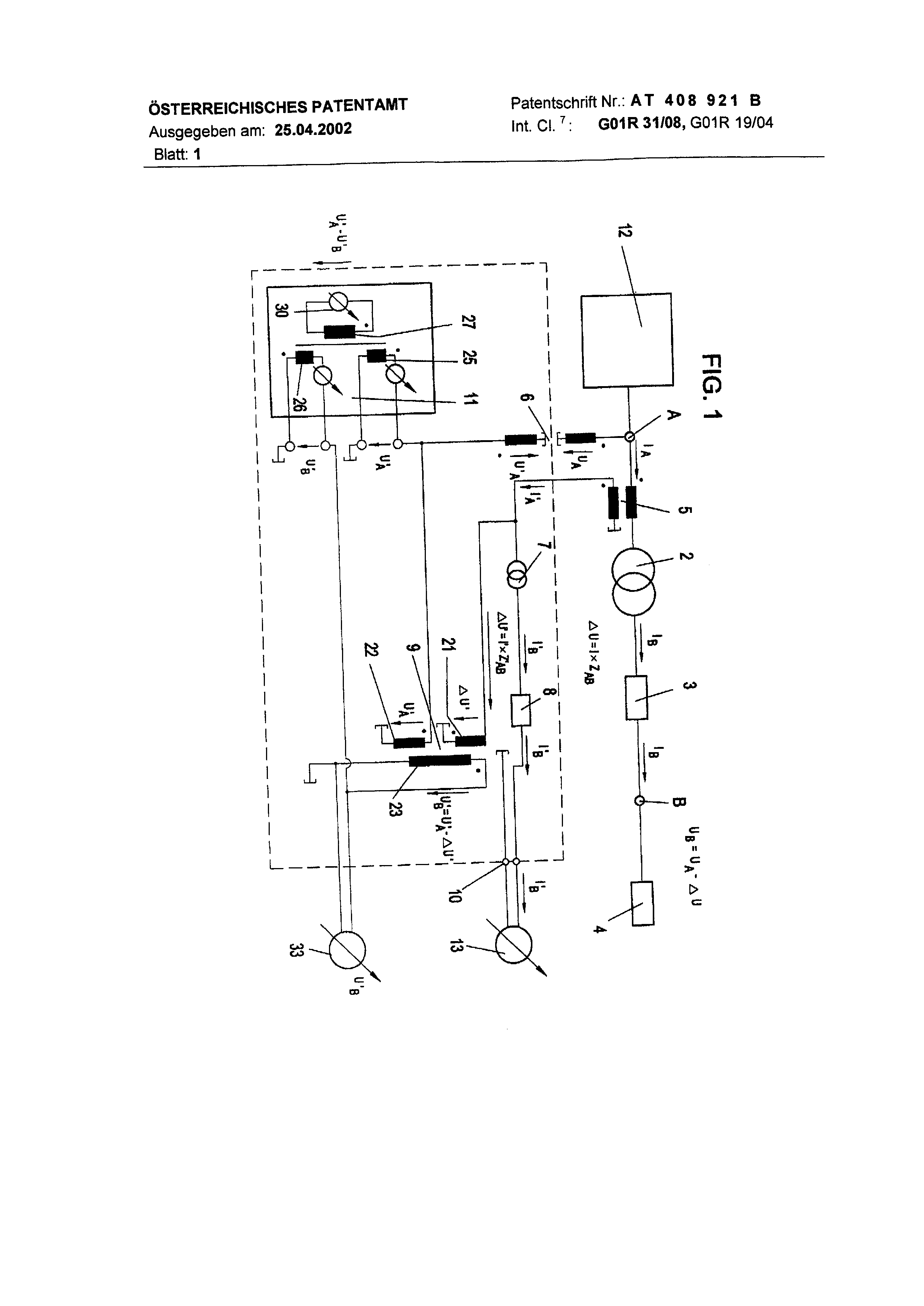
In the following the invention is described in detail on the basis a remark example represented in on design. It shows thereby Fig. 1 a diagram of an execution form of the measuring system according to invention, with which the procedure according to invention is executable.
Fig.1 points a measuring system to the telemetering of the tension arising in a far net place B and/or the Stromes_ the measuring system flowing there can depending upon need also only for Spannungsoder only for current measurements be appropriate. To the far net place B a load 4 is attached, which generally case can be formed by a combination of different loads, which can be switched off at different times einund, as it corresponds to 4 RKs 408,921 B a material net load.
The far point B is not accessible or very far either for a measurement, so that no direct measurement Stromund of voltage levels available at this point can be made.
Between a close measuring point A, which is accessible for a measurement and is feasible from measurements of, and which is far net place B different Netzteileund/or - mechanisms intended, which are compound from a transformer 2 and a connecting net 3 represented in general way as net impedance in summary and in Fig.1.
In order to be able to make Stromund stress measurement for the far point B, it is find in accordance with intended erlo that at the close measuring point A a current transformer 5 into the inlet to the far net place B is switched, whereby at the secondary winding of the current transformer 5 and/or at the reproduction unit 7, 8 a measuring device 33 for the measurement of the tension signal and a measuring device 13 are attached for the measurement of the current signal.
The river flowing by the close measuring point A lA is changed thereby into a similar Sekundärstrom I' and the changed Sekundärstrom I' by the unit for reproduction 7, 8 of impedance available between the close measuring point A and the far net place B is led, whereby the river I'B is formed, which the river eat corresponds, which in the far net place B flows. From the measurement Spannungsund/or current signal at the reproduction unit 7, 8 thus the tension U8 and/or the river can eats in the far net place B to be determined.
The reproduction unit 7, 8 is formed in accordance with a preferential execution form of the invention from an alternate circuit. The model reproductions of the transformer 2 and the connecting net 3 reached by it are to be laid out in such a way that the actual transient characteristic is copied sufficient exactly and thus a circle-faithful reproduction of the rivers and tensions is made possible. That means for the ModeUnachbildung 7 of the transformer 2 that e.g.
Switches, short-circuit impedances, internal losses and the speed ratio between Primärund secondary winding those values of the transformer 2 to correspond must.
The measuring device for the measurement of the tension signal is from a first sum potential transformer 9 with first and a second primary coil 21, 22 as well as a secondary winding 23 in an educated manner, which with its first primary coil 21 to the junction point between the secondary winding of the Stromwendlers 5 and the reproduction unit is switched and whose second primary coil 22 by a potential transformer 6 with the measuring point A is connected. The potential transformer 6 serves only the adjustment in level and can be replaced by appropriate other device and/or omitted in suitable cases.
The tension signal at the close measuring point A is supplied - after an adjustment in level - to the second primary coil 22 of the first sum potential transformer 9 and the tension signal of the first primary coil 21 of the first sum potential transformer 9 sloping at the unit for reproduction 7, 8. Thus the difference from the tension arising at the close measuring point A and the tension dropping at the reproduction unit 7, 8 is essentially formed and from this the tension available in the far net place B is determined.
The voltage drop AU' = R. ZAB with opposite phase position, developing at the reproduction unit 7, 8, is set for tension U'A to the first sum potential transformer 9 and it develops on the secondary winding the difference U'B = U'A AU', which the tension UB = U - Ith E.G. in the far net place B full-scale corresponds.
An image of the tension UB arising made smaller by its translation in the far place B results on the secondary winding of the first potential transformer 9. This tension signal U'8 is measured over a tension measuring device 33 connected with the secondary winding 23 of the first sum potential transformer 9.
Further the secondary winding of the first sum potential transformer 9 connected with a measuring device to the interference source analysis 30 is, is formed for which from a second sum potential transformer 11 with first and a second primary coil 25, 26 and a secondary winding 27.
The first primary coil 25 of the second sum potential transformer 11 is connected by a potential transformer 6, which can be replaced or omitted as managing descriptive by another device, with the close measuring point A. The second primary coil 26 5s is connected to 9 in phase position opposite in addition with the secondary winding 23 of the first SummenspanAT 408,921 B nungswandlers.
To the secondary winding 27 of the second sum potential transformer 11 a Spannungsmeßgerät 30 with frequency evaluation is attached.
The output signal resulting at the secondary winding 23 of the first sum potential transformer 9 becomes thus the second primary coil 26 of the second sum potential transformer 11 with opposite phase position opposite at the first primary coil 25 of the second sum potential transformer 11 lying close tension signal zugefi3hrt, which arrives from the measuring point A after adjustment in level at this first primary coil 25. Thus the difference becomes from at the close. Measuring point A arising tension and/or changed tension U'A and the tension U'B determined for the far net place B in an educated manner and the resulting tension frequency-evaluates.
The output signal at the secondary winding of the second sum potential transformer 11 U'AU'B is measured over a Spannungsmeßgerät 30 with frequency evaluation.
The evaluation of the measuring voltages with the measuring device 30 represents a difference measurement, which permits the investigation of the origin of disturbing missions due to the gegenphasigen admission of the primary coils 25, 26.
The measuring device for the measurement of the current signal is formed from an ammeter 13, which over the output terminals 10 into series with the unit for reproduction 7, 8 is switched.
The river flowing in the far place B eat due to the model behavior of the reproduction unit 7, 8 circle-faithfully one copies.
The invention permits it thus only the tension to measure only the river or both large ones at the far net place B.
Due to the parallel evaluation of the signals at the close measuring point A and for the far net place B the origin analysis of disturbing missions durchgefi3hrt can become on the basis of level comparisons and frequency evaluations.
The measuring system according to invention is meant as accessory equipment in the sense of a fluorescent lamp ballast to Stromund tension quality measuring instruments used so far. At the measuring point A current transformers present 5 serves to produce by means of the Sekundärstromes flowing by the model transformer 7 and the model reproduction of the connecting net 8 an image of the voltage drop arising between near measuring point A and the far net place B and to copy the river flowing in the place B. If to measure out the place B is in the net on the undervoltage side of a Verteiltrafos, one can determine Stromund tension parameter of the undervoltage-lateral net from the primary voltage side of the transformer.
Similar one can determine from the undervoltage side of the transformer Stromund tension quality of the primary voltage-lateral net.
By level comparisons of the tensions UA and UB the situation can be determined by interference sources in the net. The system has a network impedance consisting of pref. a transformer and a passive connecting network between a nearby measurement point and a remote network point. A current converter is connected at the nearby measurement point in the leads to the remote point. A unit for balancing the impedance between the nearby measurement point and the remote network point is connected to secondary side of the converter. A measurement device for measuring the voltage signal and/or one for measuring the current signal is connected to the secondary side of the current converter. An Independent claim is also included for remote measurement method. 1. Measuring system for the measurement of the tension arising in a far net place (B) and/or the river flowing there, whereby between a close measuring point (A) and the far net place (B) one from at least a transformer (2) and a passive connecting net (3) compound net impedance is present, whereby of the close measuring point (A) in actually well-known way a current transformer (5) switched into the inlet to the far net place (B) is characterized, by the fact that to the current transformer (5) secondary a unit for reproduction (7, 8) of impedance available between the close measuring point (A) and the far net place (B) is switched, and that of the interconnect point between the secondary winding of the current transformer (5) and the reproduction unit (7, 8) a measuring device (9, 33) for the measurement of the tension signal is attached and/or a measuring device (13) for the measurement of the secondary current signal is intended. 2. Measuring system according to requirement 1, by the fact characterized that the measuring device for the measurement of the tension signal from a first sum potential transformer (9) with RK 408,921 B first and a second primary coil (21, 22) as well as a secondary winding (23) is formed that the first primary coil (21) to the junction point between the secondary winding of the Stremwandlers (5) and the reproduction unit (7, 8) and the second primary coil (22) in phase position opposite in addition, if necessary over a potential transformer (6) to which close measuring point (A) is switched, and that Sekund rwicklung (23) the first sum potential transformer (9) with a tension measuring device (33) is connected. 3. Measuring system according to requirement 2, by the fact characterized that the secondary winding of the sum potential transformer (9) further with a measuring device to the interference source analysis (11) is connected. 4. Measuring system according to requirement 3, by characterized that the measuring device (30) is formed to the interference source analysis from a second sum potential transformer (11) with first and a second primary coil (25, 26) and a secondary winding (27), whereby the first primary coil (25), if necessary over a potential transformer (6), with which approaches measuring point (A) and the second primary coil (26) in phase position with the secondary winding (23) of the first sum potential transformer (9) is connected, and that the secondary winding (27), opposite in addition, of the second sum potential transformer (11) is connected with frequency evaluation with a Spannungsmeßgerät (30).
Measuring system according to requirement 1, by characterized that the measuring device is formed for the measurement of the current signal from an ammeter (13), which in series with the unit for reproduction (7, 8) is switched. 6. Measuring system after one of the requirements 1 to 5, by the fact characterized that the unit for reproduction (7, 8) of impedance from an alternate circuit with appropriate transient characteristic, available between the close measuring point (A) and the far net place (B), is formed. 7. Procedure for the measurement of the tension arising in a far net place (B) and/or the river flowing there, whereby between a close measuring point (A) and the far net place (B) one from at least a transformer (2) and a passive connecting net (3) compound net impedance is present, by the fact characterized that the river flowing by a close measuring point (A) to the far net place (B) into a similar Sekundärstrom changed and the changed Sekundärstrom by a unit for the reproduction (7, 8) of impedance available between the close measuring point (A) and the far net place (B) is led, and that Spannungsund/or current signal on the reproduction unit (7, 8) based and from this the tension and/or the river at the far Net place (B) is determined. 8. Procedure according to requirement 7, by characterized that the difference from the tension and at the unit for reproduction (7, 8) sloping tension, arising at the close measuring point (A), is formed and from this the tension available in the far net place (B) is determined. 9. Procedure according to requirement 8, by characterized that the difference from the tension arising at the close measuring point (A) and the tension determined for the far net place (B) is formed and the resulting tension is frequency-evaluated.
Procedure after one of the requirements 7 to 9, by characterized that by the computation of the transfer function of the impedance network the current signal in the distant place, lying between the measuring point (A) and the far net place (B), is determined. 11. Procedure after one of the requirements 7 to 10, by characterized that by the parallel evaluation of the signals at the close measuring point (A) and Spannungsbzw.
Current signal at the reproduction unit (7, 8) on the basis by level comparisons and frequency evaluations the origin analysis of disturbing missions one accomplishes.
HIEZU t SHEET DESIGNS