Verfahren zur aufnahme eines objektraumes
The invention concerns a procedure for the admission of an object area with an opto-electronic rangefinder after a SignaI time-of-flight method with a transmission mechanism for sending optical, insbes, from laser signals and a receipt mechanism to the receiving yon optical signals, insbes, yon laser radiation, which is reflected yon in the target area objects present. The rangefinder is combined with a Scan mechanism for the diverson of the Zes-axis of Sendeund receipt mechanism, and verfiJgt 0ber an evaluation mechanism, which determines distance values from the running time and/or the phase position of the sent optical signal. If necessary k6nnen from this Entfemungswerten in connection with the skew angles of the Scan mechanism of distance pictures produces warden (active channel). After the Scan mechanism i.e. from the range that the rangefinder is turned, from the path of rays of Sendeund/or receipt mechanism a part of the Strahlenb0ndels abgespalten and transmitted receipt sensors and determined 0ber an appropriate channel (passive channel) from these signals a picture element, whereby a distance value and a solid angle are assigned to each picture element. Rangefinder scanner liefem suctions. Distance pictures, i.e. pictures, whose picture elements in grey value stages or wrong colors codes distance values indicate. This technology found to architecture, the building industry etc. entrance within many ranges of the technology. An advantage of these systems against-upper conventional Entfernungsmel more ger it ten is that in k0rzester time one so grol'& amp; e number of points in the object area presumptuously and documented warden that from these data three-dimensional structures can be reconstructed. On the one hand arbitrary other opinions of the 3-D structure can be produced on the basis of such Enffernungsbild, on the other hand one these data can be further worked on by means of CAD (computer Aided Design) - programs.
Such systems in the steel industry found a special application: Converters, pans od. such, in which steel melts treated warden, are a relatively high Verschleir& suspended. These converters od. such verfOgen 0ber a coat from steel, which exhibits an inner lining from fireproof stones. Usually this brick lining consists of at least two layers, a inhere, the melt course-turned catch-hurries laminates and a safety brick lining directly at the steel casing. A wesenUiche task of this brick lining is to schiJtzen the steel casing before a too high thermal load. Also only a Iokaler “defect in the brick lining k6nnte to catastrophic cutter at the plant f0hren and mul from there with security to be avoided. On the other hand a repair or a Emeuerung of the brick lining is a outer erordenUich complex Prozel and causes a long-continuous operating interrupt. Around on the one hand maximum working reliability to obtain and on the other hand an m resembled Okonomi enterprise animal plant too gew hrleisten, warden the converters od. such.
examined. For this immediately after the emptying of the converter of the Beh ilter lnnenraum with a rangefinder one measures. Because of the short ME time and the close network of measuring points particularly ihrt themselves for this task of Laserenffemungsmesser scanners bew.
Typical way after the production of the brick lining of the converter the interior will measure, whereby at the converter some points of reference are taken up, which make it possible to represent the interior regarding a fixed coordinate system. With an inspection w hrend the enterprise of the plant again a measurement of the interior is durchgefiJhrt.
The coordinate systems of both photographs are set to the coincide and the Enffernungsbilder is from each other subtracted. The resulting Enffemungsbild shows then the deviations from the starting situation of the brick lining. Broken out stones or extreme Verschlei of the brick lining become visible thereby.
How above ausgef0hrt is, the decision is to i.iberholen a converter betdebswirtschaftlich very important according to the long operating interrupt and the appropriate loss of production. In order to improve the security of this decision, the measurement is suggested to more waiter abzusichem by employment of a second, unabh ngigen ME procedure. For this becomes invention in accordance with l from the signals of the passive channel, which are derived yon at least an infrared sensitiven sensor, which sensor preferably consists of a diode, a temperature level calculated and a W rmebild produced, whereby in actually well-known way each picture element of the same a Enffemungswert is assigned.
EN objects, i.e. yon objects with ei5s of ner temperature of at least 600 °C, warden favourably preferably from at least 1000 °C, sensors for the RK 412,030 B basic colours of the visible light (RGB diodes) assigned with employment for measurement yon heif.
In a favourable further training of the invention altemativ or zus itzlich to the sensors for the generation of a picture element infrared sensors, InGaAsund SI diodes can be e.g. used, which are sensibUisiert in different IR spectral regions.
With Mel proceed o.a. the kind, with which the sensitivity of the receipt mechanism of the rangefinder is reduced with applications of high temperatures according to the background brightness for the avoidance of 0bersteuerungen by the background noise, in accordance with IL a further characteristic of the invention for each picture element one determines and from this for everyone, an individual o correction value f r this calculates respective picture element zugehSrigen distance value for which, so that dutch the Reduction feel yourself ichkeit resulting in MeBfehler for each picture element are individually compensatable. With the Laserenffernungsmessung on target objects with high Oberfl ichentemperaturen (> 1000 °C) have of the target object radiated and the distance error amount ngigen of the Lasermessger it taken up radiation within the range of the Laserwellenl Inge a EinfluB on the ranging and ruff thereby one of that Oberfl ichentemperatur abh out. This effect is essentially connected on nderung the characteristics of the receipt element (in the special Avalanche photodiode) with the taken up background radiation. There the characteristics inderungen not directly from measurable KenngrSBen at the receipt element to be derived k6nnen, are favourably applicable the waiters a passive channel certain Iokale Oberfi ichentemperatur as KorrektureingangsgrSBe.
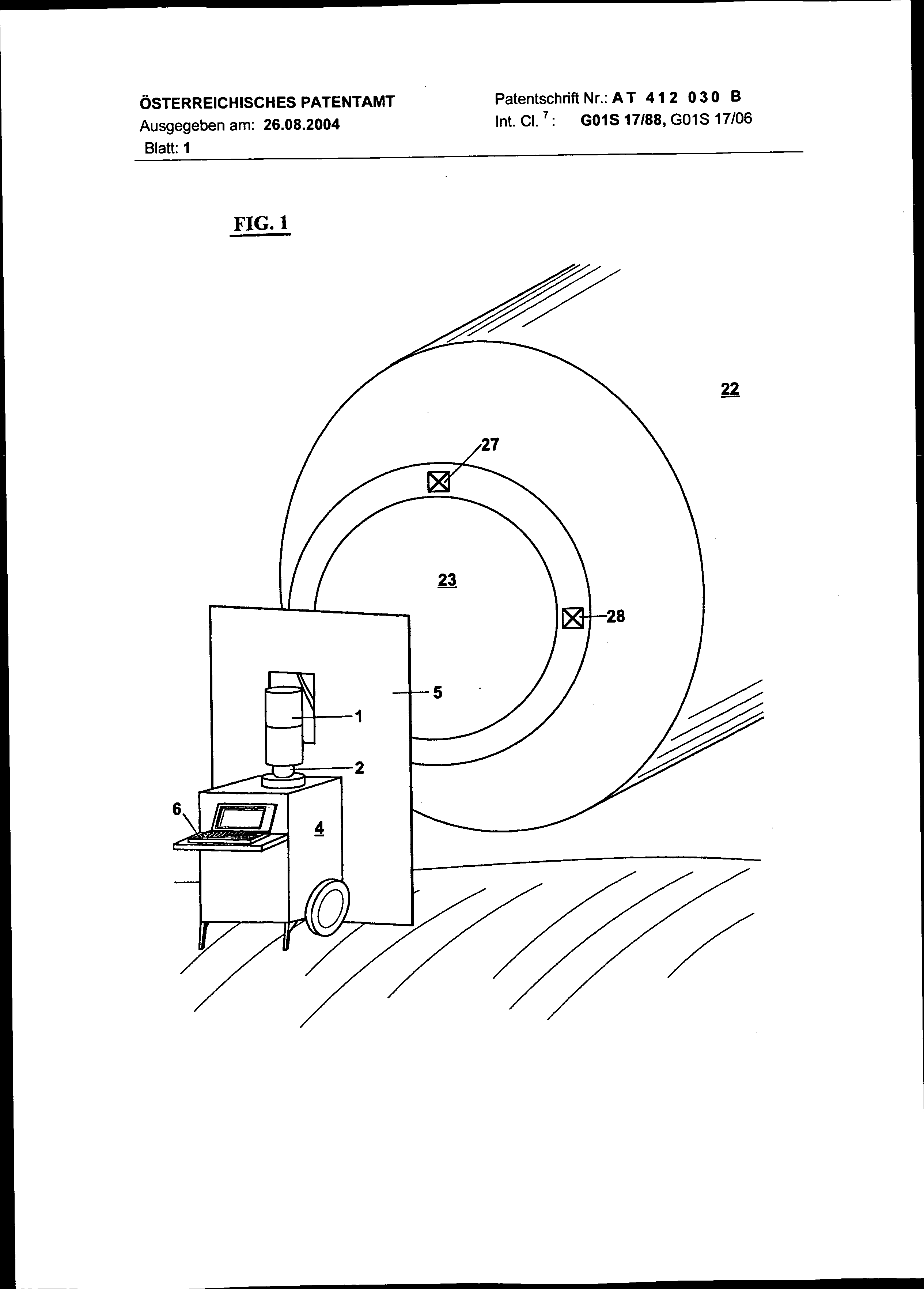
Further characteristics of the invention result from the following description of some Ausf0hrungsbeispiele and under Bezugnahrne on the design. The Fig. 1 shows Laserenffernungs scanners in MeBposition before (Dffnung of a StahI converter. The Fig. this mechanism with the converter shows 2 in the axial section. The Fig. 3 schematically the MeBkopf of the scanner, the figures 4 and 5 illustrates the inner wall of the converter represents (in Fig. 4 in form of a completion) with the Mel results. The Fig. 6 is a block diagram of the plant.
Into the Fig. 1 and 2 a scanner is shown, which verfiJgt 0ber a laser Enffernungsmesser and a picture recording unit combined with it. The Ger it is installed on a car 4, on which the ME head 1 is fastened. With a ball 2 the MeBkopf can be aligned roughly regarding the converter 22. The plant and this serving person become by a shield 5 secured, in particular against the extreme radiation from the converter interior. With 6 a computer is characteristic, more iJber that the plant gesteuerl becomes and the evaluation and storage of the results serves. At the screen of the computer the results kSnnen practically in, real-time " (Jberpr (Jft become. In Fig. the system is represented 2 in zus itzlichen details. The MeBkopf 1 consists of a lower part la, which is rigidly with the ball 2 connected. At the measuring head lower part la tiltable the measuring head upper section is lb stored around a vertical axle. This enth lt a mirror prism rotating around a horizontal axle, which is propelled by an engine with high speed. Dutch this prism is diverted both the Mel jet and the photograph jet of the picture recording, whereby the interior of the converter 23 is scanned in the form of vertically running lines. The scanning of the converter in horizontal direction the measuring head upper section becomes approximately lb (Jber the lower part la motor hinund moved. The Fig. 2 shows [Jber anschlieBt outside the steel casing 24 of the converter and the safety brick lining 25 at that inward the VerschleiBausmauerung 26.
The two brick linings consist of fireproof material and sch (Jtzen the steel casing of the converter. To the converter coat fastens, and/or into the brick lining in the range of the converter muzzle at least 3 reference marks 27 and 28, which define a coordinate system for the Konverler lnnen wall, are let in. Dutch Einfehrung of such a converter coordinate system is substantially simplified the adjustment of the MeBanlage: to set up it gen0gt the MeBwagen before the converter after markings at the ground and to align the MeBkopf if necessary vertically. Since with scanning the reference marks with are noted, this gegen0ber a fr0her taken up picture kSnnen manually during the evaluation of the pictures or aligned and anschliel end also automatically to the coincide to be set. With the help of the new procedure it is to be taken up mSglich, at the same time with a Entfemungsbild a congruent W irmebild. The EnffemungsbJlder becomes generally with Enffemungsbildem vergJJchen, which men s5 either after the brick lining or anl iBlich the last inspection of the converter aufgenom3 RK 412,030 B are. From subtraction of the two pictures a difference picture results. For the relief of the interpretation of such Balder these are spent in wrong color coding or in HShenschichtenlinien. The Fig. 4 and 5 shows such screen masks and/or expressions f0r a completion of the internal coat 29, the converter 22 and the ground 32. With 31 HShenschJchtenlin] EN are characteristic. The distance pictures are represented in similar way. Since this v6llig is congruent with the distance pictures, they kSnnen not only alternatively to be spent, but also each other (to be.iberlagert. In addition, places in the brick lining with high Verschleill or with Ausbr0chen von Feuerfest-Steinen appear both in the distance picture and a entsprechende/1, nderung more gegeneber a fr0heren condition, are clearly visible in the W irmbild lo. As a result of the reduction of the thermal isolation a erh6hter W arises rmeflu yon converter lnnenwand to the steel casing 24, thus dal the places with high catch-hurries or AusbrLichen in the W irmebild clearly k more ilter appears within such ranges. Since the two expenditures developed muddled in accordance with vSIlig different Mel, a 0bereinstimmung of the results is an important Best itigung the results.
The figure 3 shows the Scan unit of the measuring head 1 in zus itzlichen details. From the Steuerger 3 a laser diode 9 it is fed, their radiation by an optics 10 in the Unendl6 che illustrated. In substantial parallel aligned Strahlenb ndel is diverted reflected prism 8 by the 3-seitige, which around an axle 7 rotates and one propels by an engine 11. By a angle decoder 12 connected with the engine 11 a position signal A to the Steuerger it 3 r0ckgemeldet. By the turn of the prism 8 0berstreicht the laser Strahlenbendel in the object area an angle of approx. 80 °. Laser radiation is reflected by goals in the object area and konzentdert by an optics 13 on a receipt diode 14. The appropriate Empfangs-Strahlenb0ndel is turned back by the same mirror prism 8, so that Sendeund receipt jets are essentially parallel aligned. Between the optics 13 and the diode 14 a beam splitting prism 15 is arranged, whose part-reflected Teilungsfl che 16 is coated dichroitJsch, so that infrared laser light can pass these flat steel bars che praldJsch ungeschw icht, w it-ends visible light and infrared radiation of other Wellenl nge on a second beam splitter prism 55 is reflected. This prism has two semireflecting Lichen 56 and 57, which are likewise dichroitisch coated.
This prism splits the incident light for example into the 3 basic colours RGB or into infrared of different Wellenl ingen. The appropriate sensors are marked with 17, 58 and 59. With such a mechanism zus =itzlich for the distance picture a congruent color (and/or a Falschfarben w irme) - video picture can be produced. As ihnt already initially erw, by the rotary mirror prism 8 the object area is scanned in the form of vertical lines. The mechanisms described above are arranged in the measuring head upper section l b. This OberteJl is shifted by an engine 18 in a motion reciprocating around a vertical axle. A angle decoder 19 connected with the engine 18 supplies 3 to the Steuerger it the skew angle q) appropriate R0ckmeldesignal. In the case of a whole revolution of the mirror prism 8 the jets scan the object area in the form of 3 lines. From geometrical Gr can in gew ihlten interpretation of the 120 ° only one angle standing per line to the Verfi3gung yon 40 ° f0r the ranging and the picture recording nden to be used. In analogy to the television engineering, Abtastl (cke designated " the laser beam is directed by the prism 8 on eJnen light conductor 20. A defined L nge exhibiting light conductors transmits yon to the transmission diode 9 outgoing laser impulse of the receipt diode 14. In a certain angle position of the prism 8 the Laserstrahlenb0ndel meets the light conductor 20. The Steuerger it 3 scolded from there with a defined (- value the signal processor on a calibration mode, in which the of that determined distance measure value with the act chlichen, by which Linger of the light conductor 20 defined distance is compared. In the case of deviations a correction value is computed, which becomes with the computation of the distance of goals in the object area from the running time of the laser impulses according to ber0cksJchtigt. In similar way in the Abtastl0cke of the prism 8 a Referenzfl is illustrated iche 21 on the diodes 17, 58 and 59. With reaching a defined A-value the video channel is switched to an alignment mode and depending upon training of the Referenzfl iche 21 a because - or black alignment durchgef0hrt. The video channel can be adjusted nat0rlich also on a defined grey value.
The figure 6 shows ites 3 RK 412,030 B of the laser scanner in form of a block diagram schematically the structure of the Steuerger in accordance with l of the invention, whereby in this diagram only those are represented to the deflecting systems of systems downstream. With 30 a laser transmitter is designation that the laser diode 9 heads for, which is upstream the optics 10, which preferably illustrates the emitter of the laser in the infinite. Apart from the transmission optics 10 a Empffingeroptik 13 is intended, whose Z-axis is aligned parallel to that the transmission optics 10. In the path of rays of the Empf ingeroptik 13 a beam splitting prism 15 is intended. The Empffingeroptik 13 konzentdert on the one hand the radiation on the receipt diode 14, reflected generally vaguely by a goal in the path of rays of the transmission optics. With advantage as receipt diode 14 a Avalanche diode is used. Preferably Sendeund receipt diodes are co-ordinated in its e spectral characteristic, whereby the receipt diode their maxJmale spe - rale sensitivity within the range exhibits, in which the transmission diode maximally emitted. Since however beside the KunsUichtquellen most diverse of the transmission diode and of the goal reflected radiation much StSrstrahlung in the form of daylight or light emitted the receipt diode 14 yon empffingt, it can be favourable, the receipt diode a m6glichst narrow-band to set is optical filter forward which exhibits its maximum transmission in the spectral band, in which the laser emitted.
By the beam splitter prism 15 a part is concentrated from the object area of radiated light on a receipt diode 17 (and on the further, diodes 58 and 59 not represented in this figure). With such a mechanism from there parallel Libero the second, passive channel a Farboder Falschfarben w irmebild picture of the Objektfeldes can be noted to the distance picture (active channel). The laser transmitter 30 covers a surge generator, which heads for the laser diode 9. The laser transmitter gives, if it is headed for accordingly by the processor 34, a consequence of laser impulses, to suctions. Bursts, off. Such Burst can cover 1-50 impulses depending upon instruction given by the processor. By means of one VerzSgerungsgenerators 35 controllable of the processor 34 the individual impulses of a Bursts in their phase position kSnnen to be verfindert, whereby the phase shift takes place periodically.
The of that diode of 14 received signals in amplifiers are irkt and worked on irkerund an analog signal processor stage 36 amplifiers. In a mSglichen training form in this way worked on signals in a similar to /DigitaI converter 37 with a SAM polarizing frequency are digitized by for example 60 MHz. These gesampelten echo signals are put down in a memory 38. According to the phase shift of the transmission impulses of a Bursts gegeni more ber the SAM polarizing frequency the gesampelten echo gnaJe are put down into different memory cells. If the phase shift exhibits like ausgefi3hrt a Periodizit t above yon 5 impulses, then the gesampelte pulse is added after 5 impulses on the preceding. Um3s seizes a Burst e.g. 50 impulses and the digitized impulses with the period 5 “verk is immt”, then in each case in a memory cell 10 digital values are added and the SAM polarizing frequency of 60 MHz appear ert around the frequency of the Verk immung vergr61, in the available example on 300 MHz, so that the scanning theroem can be kept regarding the reconstructed receipt impulse.
In an alternative AusfiJhrungsform mittens a ZeitintervalI Digitalisierungseinrichtung 37 the run time interval between Sendeund receipt impulse is digitized and the results in a memory 38 is put down.
The entire mechanism is clocked by a Clock generator 52. The processor 34 and the data memory 38 are connected by a data bus, which is marked with 39 schematically suggested and. Furthermore to this data bus 39 a program memory 40 f IR the processor 34 are attached, as well as a data buffer 41, into which after a first evaluation by the processor 34 raw data are put down, which are picked out at the end of the Messzyklus. From these raw data in the program memory put down algorithms a Entfemungswert fi3r each individual raster element is also determined.
Yon the diode Tripel 17, 58 and 59 supplied signal in the video processor stage 42 amplifiers one irkt and one continues to work on. This video processor is 0ber the bus 39 with the processor 34 and the other BI6cken of the system, insbes, with the digital bit map memory 43 and the video interface 44, in connection. To the individual raster elements the geh6rigen picture coordinates is fed yon the two Ablenkeleldronik EJnheiten 45 and 48 i) more ber the Daienbus 39 into the system.
RK 412,030 B the processor 34 determined from the received signals the amplitude values, the Signalrauschverh ltnis etc. and specifies the number of the impulses per Burst due to these values and heads for the laser transmitter 30 accordingly. At the same time Gber the data bus 39 an appropriate instruction is sent to the Ablenkelektroniken 45 and 46. With ungGnstigen conditions (low amplitude of the receipt impulses, small signal /Rauschverh iltnis, grol e measured value dispersion) the number of the impulses per Burst is erhSht and the sweep rate of the Scan mechanism is reduced accordingly. This adjustment knows individually f0r each individual raster element, fiJr a line yon raster elements or f (Jr the whole Scan cycle to take place. The invention relates to a method for the recording of an object space with an opto-electronic distance sensor by a signal propagation time method, with a transmitter for transmitting optical signals, in particular those of a laser, and a receiver device for receiving optical signals, in particular laser radiation, which is reflected from objects located in the target space. The distance sensor is combined with a scanning device for deflecting the optical axes of the transmitter and receiver device, and it has an evaluation device, which from the propagation time or phase angle of the optical signal emitted ascertains distance values. Downstream of the scanning device, that is, out of the region oriented toward the distance sensor, part of the beam is split off from the beam path of the transmitter and/or receiver device and is directed to receiver diodes or the like, and from the corresponding signals, a pixel is ascertained and each pixel is assigned a distance value and a space angle. 1. Procedure for the admission of an object area with an opto-electronic Enffernungsmesser after a SignaI time-of-flight method with a transmission mechanism to sending optical, insbes, yon laser signals and a receipt mechanism to the receiving of optical signals, insbes, of laser radiation, which is reflected yon in the target area objects present, furthermore with a Scan mechanism to the diverson of the Zes-axis of Sendeund receipt mechanism, furthermore with an evaluation mechanism, which determines Enffemungswerte from the running time and/or the phase position of the sent optical signal, whereby from this Enffernungswerten in connection with the skew angles of the Scan mechanism a Enffemungsbild is produced if necessary (active channel) and after the Scan mechanism from the path of rays of Sendeund/or receipt mechanism a Tell of the Strahlenb0ndels and receipt sensors abgespalten transmitted and Gber an appropriate channel (passive channel) from these signals a Bildelemerit determined is marked, whereby a Enffernungswert and a solid angle are assigned to each picture element, by the fact that from the signals of the passive channel, which are derived from at least an infrared sensitiven sensor, which sensor preferably consists of a diode, a temperature level calculated and a W is produced rmebild, whereby in actually well-known way each picture element of the same a distance value is assigned. 2. Procedure for the admission of an object area after patent claim 1, by it characterized that for determines each picture element of the Weft of the background brightness or a temperature level and from this fGr everyone, for which respective picture element zugehGrigen distance value an individual correction value is calculated fGr these, so that dutch the reduction of the sensitivity, which is necessary with applications of high temperatures for the avoidance of Ubersteuerungen dutch the background noise, resulting in Mef error is individually compensatable fGr each picture element. 3. Vordchtung to the DurchfGhrung of the procedure after patent claim 1 or 2, by the fact characterized that to the measurement of welfare EN objects, i.e. yon objects with a temperature of approx.
600 °C and more hGher, sensors fGr the basic colours of the visible light (RGB diodes) is assigned. 4. Device to the Durchfehrung of the procedure after patent claim 1 or 2, by the fact characterized that alternatively or zus tzlich to the receipt sensors for the generation of a picture element infrared sensors, e.g. InGaAsund SI diodes, are used, which are sensitized in different IRSpektralbereichen.