Adjustable reflector
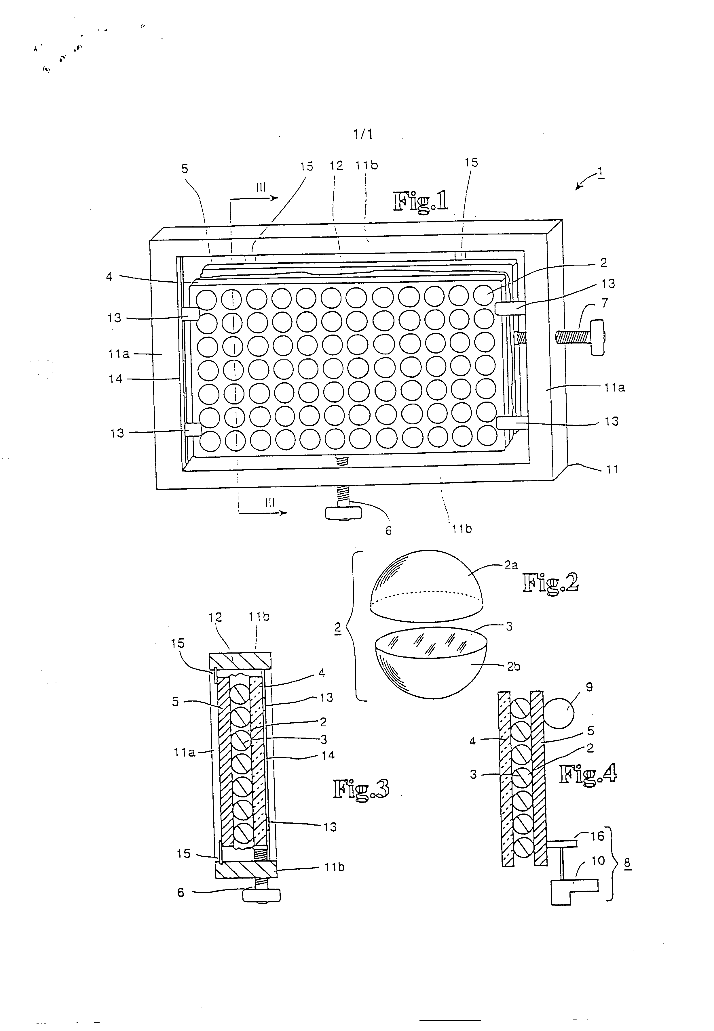
PCT/EP 97/05122 Munich, WO 98/14815 17.08.1998 Stephen C. O'Hara.Smith Pat 1555/2-PCT Adjustable Reflector The invention relates to an adjustable reflector which has several rotatable reflector elements each of which has a reflective surface. Reflectors are generally used to deflect electro-magnetic radiation such as light. Reflectors are frequently used for advertising purposes, in connection with signalling systems or for the purpose of directing sunlight in a particular direction - to a solar collector for example. The reflectors or its reflector elements must be rotated in order to change the angle of reflection, e.g. to adjust to the changing position of the sun. An adjustable reflector of the above type is known from GB 2 255 195 A. In the case of such a reflector, it is not necessary to align the entire reflector, which is frequently very bulky, in order to change the direction of the surface normal of the reflector surface and thereby the direction of the reflected rays; it is sufficient tO adjust the individual rotatable reflector elements of this type of reflector in such a way that the surface normal of their respective reflector surfaces are rotated to a particular direction thereby obtaining the required reflection angle. With regard to the state-ofthe-art reflectors of this type further reference is made to US 4 304 218 and FR 2 688 601. In the case of the known adjustable reflectors, however, connecting the reflector elements to rotate them together in parallel has proven to be a major technical problem. The requirements in relation to precision and speed when changing the direction of the reflector elements could only be met to a decidedly limited extent in the case of the state-of-the-art reflectors, owing to the complicated structure of the reflector elements and/or the operating mechanism. Nor could the known reflectors be used in the case of requirement.controlled systems where the problem posed was to change the performance of a solar collector by adjusting and/or "de-adjusting" the reflector with a fast response time. It is an object of the present invention to overcome or ameliorate at least one of the disadvantages of the prior art, or to provide a useful alternative. According to the invention there is provided an adjustable reflector, which has several rotatable reflector elements, each of which has a reflective surface, wherein the reflector elements are balls which are at least partially transparent and which are mounted between two plane-parallel plates, of which at least one plate consists of a transparent material and whereby at least one of the two plates can be moved relative to the other one of the two plates while maintaining its distance from the other plate. While, according to the theory put forward by the invention, the spherical reflector elements are mounted between two plane-parallel plates of which at least one plate consists of a transparent material, surprisingly, the reflector elements can be connected together in parallel to rotate them together in a particularly simple and elegant way as regards design. Since, according to the invention, one of the two plates can be moved relative to the other one of the plates while maintaining the distance between them, by moving them appropriately, the spherical reflector elements mounted between the two plates are rotated in the same direction, so that the surface normals of their reflector surfaces can be adjusted or rotated in the required way. A relative movement between the two plates of the order of one circumference of the reflector balls permits a rotation of the surface normals of the reflector surface through 180°. This means that with a preferred ball diameter of 2.5 cm and a ball circumference of approx. 7.85 cm, the entire adjustment range of 180° will be covered when a plate is moved by as little as 7.85 cm. In practice, however, much smaller adjustment ranges are adequate. Owing to the short adjustment distances, the adjustment can be made within a few seconds. In consequence of the fast response times for the reflector according to the invention this can also be used for requirement-controlled systems where the problem posed is to change the performance of a solar collector by adjusting and/or "de-adjusting" the reflector with a fast response time. Advantageously, at least in a preferred from, the present invention may provide an adjustable reflector which can be built cost-effectively and comparatively small in size and which would be sturdy and robust, and one which could be aligned, i.e. adjusted, with comparatively few expensive systems and with fast response times. In this case the reflector elements are to be connected to rotate them together in parallel in a particularly simple and elegant way as regards design. In a particularly advantageous embodiment of the invention, the reflector elements can be rotated in at least two directions so that surface normal of the reflector elements can cover almost any direction in a hemispherical range. It is particularly advantageous if the reflector elements are interconnected and can be rotated together, preferably in parallel. An individual adjustment of each reflector element can then be dispensed with. The reflective surface may consist of an aluminium or silver foil covering, particularly if the reflector is to be used for visible light. In a further advantageous embodiment of the invention, the balls may consists of glass or plastic. Glass is preferable because of its optical properties while plastic balls are less expensive to manufacture. According to a further embodiment each reflective surface is arranged in the equatorial plane of the balls. From a technical manufacturing perspective, this can best be done if the balls consist of two hemispheres and the reflective surface is applied to the fiat surface of one of the two hemispheres. In a further advantageous embodiment of the invention, a device to move at least one of the two plates in one direction relative to the other one of the two plates is provided. A further advantage would be obtained if a further device is provided which facilitates moving one of the two plates in another direction perpendicular to the first direction. With two such devices, the surface normal of the reflection surface can be set to any direction required in a solid angle of a hemisphere (2rt). The device and/or devices for moving at least one of the two plates in directions perpendicular to one another, may consist of simple, manually operated adjusting spindles. However, in a particularly advantageous embodiment of the invention, it is intended to use a motor which will facilitate a fully adjustable movement setting in one and/or the other direction, of at least one of the two plates relative to the other one of the two plates. This should preferably be a linear or step motor with gears. This version of the invention will facilitate easy setting of the surface normal and thereby of the reflection angle and could be remote controlled or - in a further advantageous version - controlled by a computer-supported system. With a computer-supported system for example, where the reflector is used in conjunction with a solar collector, the reflection angle could be adjusted in accordance with the changing position of the sun so as best to direct the sun's rays at the solar collector. The computing power of a standard personal computer (PC), has proven sufficient for this type of control, even if control of an array of several reflectors is required. In order to ensure even pressure on the reflector elements mounted between the two plates, ideally, at least one of the two plates should be coated with an elastic substance, preferably a foam material. In a preferred version, it is further intended to fit the adjustable reflector which is the subject of this invention, in a housing frame. A preferred embodiment of the invention will now be described, by way of example only, with reference to the accompanying drawings in which: Figure 1: a perspective view of an adjustable reflector according to a first embodiment; Figure 2: a perspective view of a reflector element consisting of two hemispheres; Figure 3: a cross-section along the line III-III in figure 1; and Figure 4: a cross-section corresponding to the cross-section in figure 3 for a modified embodiment. The adjustable reflector 1 shown in figure 1 has a first transparent plane-parallel plate 4 which can consist of glass or plastic. At a distance from the first plate 4, there is a second plate 5 parallel to it. Spherical reflector elements 2 are mounted between the two plates 4 and 5. In the drawing there are a total of 7 x 12 spherical reflector elements 2, although in practice, there could naturally be a far larger number of reflector elements 2, depending on the overall size of the reflector. A typical size for a reflector 1 could be one square meter. A typical size for the spherical reflector elements 2 could be 2.5 cm in diameter, whereby the individual balls would be arranged at intervals of a few millimetres from one another so that there could be approx. 35 balls in one direction and a total of approx. 1225 balls in one reflector 1. The two plates 4 and 5 are connected to one another with an expansion bellows, creating an airtight connection so that no dirt can penetrate the interior space sealed by the two plates 4 and 5. Nevertheless, the two plates 4 and 5 are not rigidly connected to one another but can be moved relative to each other, each in its own plane and within certain limits. Figure 2 shows the structure of a reflector element 2. As can be seen from figure 2, a reflector element 2 consists of two transparent hemispheres 2a and 2b, preferably made of plastic. A reflector surface 3 is applied to the cross-section plane of hemisphere 2b in the form of aluminium foil bonded to it. The two hemispheres 2a and 2b, shown separately in figure 2 for illustration purposes, are bonded to one another with a glue. In the adjustable reflector 1 shown in figure 1, the reflector elements made in this way are held between the two plates 4 and 5 by static friction. As a further aid, an elastic foam layer applied to the back of plate 5 in figure 1 ensures that all the reflector elements 2 are largely subject to the same pressure, which is sufficient to guide them frictionally between the two plates without slippage. The two plates 4 and 5 are supported flexibly in a rectangular frame 11. The frame consists of two vertical limbs 11a and two horizontal limbs 11b. The method of support chosen facilitates moving plate 4 in a vertical direction (vertical relative to the illustration in figure 1) and moving plate 5 in a horizontal direction (horizontal relative to the illustration in figure 1). To this end, plate 4 is fitted with a total of four sliding feet 13, each of which engages in corresponding guide grooves 14 fitted in the vertical limbs 11a of frame 11. Using a threaded spindle 6 which is carried in a threaded hole in a horizontal limb 11b of frame 11 connected at the top with plate 4, plate 4 can be moved in a precise vertical direction and the movement is precisely in the plane of plate 4. In the same way, the rear plate 5 illustrated in figure 1 is fitted with sliding feet 15 which engage in guiding grooves (cannot be seen in the illustration in figure 1) in the horizontal limbs 11b of frame 11, thus facilitating horizontal movement of plate 5. Using a further threaded spindle 7 which is carried in a threaded hole of a vertical limb 1 la of frame 11, rear plate 5 can be positioned precisely in a horizontal direction. By guiding plates 4 and 5, it is possible to ensure that they always remain parallel and that the distance between them remains constant so that the spherical reflector elements 2 fitted between plates 4 and 5 are always pressed with a constant force. By using threaded spindle 6 and thereby moving plate 4 in a vertical direction (vertical relative to the illustration in figure I), the reflector surfaces 3 can be aligned in a vertical direction. Moving plate 4 by just a few centimetres is sufficient to set almost any angle required in a vertical direction. It is not necessary to install expensive rotating devices which require a lot of space. In the same way, by moving rear plate 5 horizontally (horizontally relative to the illustration in figure 1) just a few centimetres, an adjustment of the surface normals of reflector surfaces 3 to any angle required can be made. The cross-section illustration in figure 3 provides a particularly good picture of how the spherical reflector elements 2 are mounted between plates 4 and 5 which are sealed by expansion bellows 12. Figure 3 in particular shows the sliding feet 13 fitted to plate 4, which run in the guiding groove 14 in order to facilitate vertical movement of plate 4 (vertical relative to the illustration in figure 3), for which the adjusting spindle 6 is used. Figure 3 also shows the sliding feet 15 which are carried in the horizontal limbs 11b of the frame in order to ensure the horizontal guidance of plate Figure 4 shows an illustration of a modified version corresponding to the crosssection illustration in figure 3. In this version, in which the reflector elements 2 are again fitted between two plates 4 and 5, one of the two plates, specifically the transparent plate 4, is rigidly connected to a frame (not illustrated). Only plate 5 is flexibly supported. In this case a motor 10 with gears and a driving wheel 16, frictionally connected to plate 5, are used to move it. With this driving device consisting of motor 10 with gears and drive wheel 16, plate 5 can be moved perpendicular to the line of projection, i.e. in a horizontal direction. A corresponding device 9 has been built to move plate 5 in a vertical direction, but has been fitted at an angle of 90°. For reasons of clarity, details of the mountings for driving devices 8 and 9 have been omitted. Although the invention has been described with reference to specific examples it will be appreciated to those skilled in the art that the invention may be embodied in many other (57) Abstract The invention concerns an adjustable reflector (I) which comprises a plurality Lof reflector elements (2) which each have a reflector surface (3) and are pivotably disposed. The reflector elements (2) can pivot in at least two directions and/or are mutually coupled and pivotable together. The reflector surface (3) can comprise a tensioned aluminium or silver foil. The reflector elements (2) can be at least 11a-- )oooooooooo partially transparent spheres. According to a further configuration, the reflector 4 )OOOOOOOOOO surface is disposed in an equatorial plane of the spheres• It can be produced )OOO00( in a particularly advantageous manner from the point of view of manufacturing)@OOOOC I W techniques if the spheres are each assembled from two hemispheres, the reflector i surface being formed on the flat surface of one of the two hemispheres• Preferably, in order to be parallel and jointly pivotable, the reflector elements can be coupled 6 I1b in a particularly structurally simple and elegant manner if, according to a further advantageous embodiment of the invention, the spherical reflector elements are clamped between two plane parallel plates of which at least one is made of a transparent material. If one of these two plates is displaceable relative to the other plate whilst the spacing therebetween is maintained, a corresponding displacement rotates the spherical reflector elements, clamped between the two plates, in the same direction, such that the surface normal of their reflector surface is adjusted or pivoted in the desired manner. 1. Adjustable reflector, which has several rotatable reflector elements, each of which has a reflective surface, wherein the reflector elements are balls which are at least partially transparent and which are mounted between two plane-parallel plates, of which at least one plate consists of a transparent material and whereby at least one of the two plates can be moved relative to the other one of the two plates while maintaining its distance from the other plate. 2. Reflector in accordance with claim 1, wherein the reflector elements can be rotated in at least two directions. 3. Reflector in accordance with claim 1 or 2, wherein the reflector elements are interconnected and can be rotated together. 4. Reflector in accordance with at least one of the claims 1 to 3, wherein the reflective surface is covered with aluminium or silver foil. 5. Reflector m accordance with at least one of the claims 1 to 4, wherein the balls are made of glass or plastic. 6. Reflector in accordance with at least one of the claims 1 to 5, wherein the reflective surface is arranged in the equatorial plane of the balls. 7. Reflector in accordance with at least one of the claims 1 to 6, wherein the balls consist of two hemispheres. 8. Reflector m accordance with claim 7, wherein at least one of the two hemispheres consists of a transparent material. 9. Reflector in accordance with any one of the claims 1 to 8, including a first device adapted to move at least one of the two plates in a first direction relative to the other one of the two plates. 10. Reflector in accordance with claim 9, including a second device is adapted to move at least one of the two plates in a second direction relative to the other one of the two plates and perpendicular to the first direction. 11. Reflector in accordance with claim 9 or 10, wherein the devices for moving the plates have a motor which should have a fully adjustable setting for moving at least one of the two plates relative to the other one of the two plates in the first and/or the second direction. 12. Reflector in accordance with claim 11, wherein the motor is a linear or step motor with gears. 13. Reflector in accordance with at least one of the claims 9 to 12, wherein the device for moving the plates in the first and/or the second direction is controlled by a computer- supported system. 14. Reflector in accordance with at least one of the claims 1 to 13, wherein at least one of the two plates is coated on the side facing the reflector elements with an elastic substance to distribute the pressure on the reflector elements evenly. 15. Reflector in accordance with claim 14, wherein the substance is foam. 16. Reflector in accordance with at least one of the claims 1 to 15, wherein the reflector is fitted in a housing frame. 17. An adjustable reflector which has several rotatable reflector elements, each of which has a reflective surface, substantially as herein described with reference to any one of the embodiments of the invention illustrated in the accompanying drawings.
DATEDthis 8th Day of November 1999 STEPHEN C. O'HARA-SMITH Attorney: CAROLINE M. BOMMER Fellow Institute of Patent Attorneys of Australia of BALDWIN SHELSTON WATERS
CPC - классификация
FF2F21F21VF21V1F21V17F21V17/F21V17/0F21V17/02F21V7F21V7/F21V7/1F21V7/10F24F24SF24S2F24S20F24S202F24S2023F24S2023/F24S2023/8F24S2023/85F24S2023/87F24S2023/872F24S203F24S2030F24S2030/F24S2030/1F24S2030/11F24S23F24S23/F24S23/7F24S23/77F24S3F24S30F24S30/F24S30/2F24S30/20GG0G09G09FG09F1G09F13G09F13/G09F13/1G09F13/16YY0Y02Y02EY02E1Y02E10Y02E10/Y02E10/4Y02E10/40Y02E10/47IPC - классификация
FF2F21F21VF21V1F21V17F21V17/F21V17/0F21V17/02F21V7F21V7/F21V7/1F21V7/10F24F24JF24J2F24J2/F24J2/5F24J2/52F24SF24S2F24S23F24S23/F24S23/7F24S23/70GG0G02G02BG02B2G02B26G02B26/G02B26/0G02B26/08G02B7G02B7/G02B7/1G02B7/18G02B7/182G09G09FG09F1G09F13G09F13/G09F13/1G09F13/16Цитирование НПИ
FR 2688601GB 2255195
US 4304218