DEVICE AND METHOD FOR SYNCHRONISING A SYSTEM OF COUPLED DATA PROCESSING FACILITIES
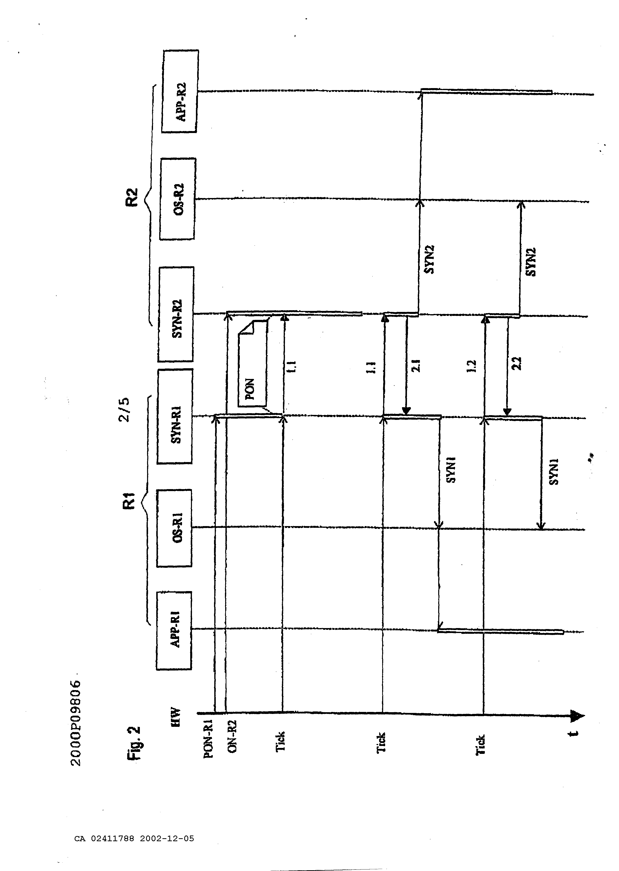
Device and method for the synchronizing a system of coupled data processing facilities The present invention concerns a device and a method according to the generic terms of claims 1 and 3. In technical areas, in which strict safety regulations have to be met, systems of networked computers, also described as multi computer systems, are used to fulfill the required safety standards with redundancy. Multi computer systems can be built on so-called diversity hardware. A multiple computer system is based on diversified hardware, if single components like processors in particular have a different architecture and are also mostly produced by various producers. Errors are recognizable with diversified hardware, which are inherent to a determined computer, and in particular processor. To especially facilitate the maintenance and logistics, the so-called unitary hardware is increasingly used, which is marked by a homogenous hardware structure. Typical multi computer systems are known under the terms 2v2 and 2v3 and further configurations. Two computers are networked to each other by an interface at a 2v2 system. During a for example periodically carried out comparison of status data of both computers, a further processing of the process data occurs only then, if both computers each have determined equality during this comparison, a failure corrective action occurs at a present inequality. All or at least some safety relevant orders are not carried out at inequality and the system to be controlled is brought into a safe status. Three computers are each connected by an interface with other computers at a 2v3 system. A further processing of process data occurs only then at a paired carried out comparison of status data, if two computers each have determined equality at a comparison. It is assumed thereby, that the third computer is in a full of errors status. Such methods are known under the term "voting". To fulfill the requested safety standards, a solution for unitary hardware is known, in which the corresponding processors are each supplied with a system cycle and both processors process the identical software. For a comparison of data status, data flow is carried out on the bus level and is recognized as an error with an inequality. This solution is disadvantageous because a special comparator circuit is necessary, which considers the running time differences. A further solution exists therein, to compare those memory contents at determined times, from which the consistency of the safety relevant data is and in particular should be relevant. The previously mentioned solutions, with exception of comparison on the bus level, have in common that these mechanisms are always visible in form of especially provided codes within the applications at the development of safety relevant applications. In particular, each person entrusted with the development of such an application, has to deal not only with the application but also with the synchronizing of computers and/or of pending incoming and outgoing data. An additional common disadvantage of the mentioned solutions is the use of individual clock generators on the computers, which have to be synchronized, expensively, from the time of starting the system, which again contains risks during the start-up. The task of the present invention is therefore to indicate a device and a method which enables one to realize applications concerning safety regulations wherein a clear simple separation of the classical application and synchronization is possible. This task is solved by the indicated disclosure in the patents claim 1 and 3. Advantageous designs of the invention are indicated in further claims. In multi computer systems, for example 2v2 or 2v3 systems, only an active hardware master clock is necessary according to the invented system, therefore the risks emerging from a mutual synchronization of hardware master clocks is eliminated. A cycle is therefore copied by the method of time synchronization so that one is also available to a networked computer. Because each computer is provided with a hardware master clock, it is determined at the system's start which computer is equipped with the so-called master-clock. This assignment is changeable during operation upon request. The device according to the invention and the method according to the invention are generally applicable to all types of computers. To receive a fitting separation of the synchronization of the applications, so-called subsystem steps for application processes have been introduced in the method according to the invention. These subsystem steps are independent from the operating system and hardware. This allows a splitting of the application processes into constant process elements without having to consider the task of the application processes. The subsystem steps of an application process are input, processing, and output. Between these steps lie the synchronizing points for an invalid character check. The results of these subsystem steps are compared to the redundancy computers. This allows in case of an error, a fast access into the system which is particularly important at safety critical applications. A further advantage at correcting errors is the correcting possibility, because a subsystem step can be corrected easier than a whole process. The method according to the invention provides a standardized data interface for the mutual data exchange of computers. The data to be controlled can be assigned simply and safely to the right processing steps by the standardization of the interface in connection with the definition of the synchronization points. From this comes the advantage that computers with multi task systems can also use the method according to the invention without adding further systems and without limitations. Data control can be parameterized by the flexible structure of the messages in the method according to the invention, which means, the message length can be adjusted to the demands, so that no data or on the other hand a great amount of data is delivered in an extreme case. This adds, among others, to the optimization of the synchronization time. Additionally, the data itself can be also parameterized to execute a voting or for an improved comparison of the analogous values. Model examples of the invention are explained in more detail according to the drawing. Thereby show: Figure 1 the system architecture, Figure 2 time synchronizing of a 2 v2 system, Figure 3 data synchronizing of a 2v2 system, Figure 5 general data synchronizing structure and Figure 4 a message structure. Figure 1 shows a typical structure of a system architecture with four layers of, hardware HW- LAY, driver BSP-LAY, operating system OS-LAY and Application APP. This structure allows a separation in layers of the methods of the hardware. It is evident, that applications APP operate directly within time critical functions, without detours to the operating system OS-LAY. In the system according to the invention, the units multi computer communication driver. This means that the application APP is already separated from the synchronizing SYN&CHK by the architecture. The synchronizing unit SYN&CHK and the communicating can work independently for themselves and are applicable to all applications APP, as well as to the operating system OS-LAY. The driver units work together with the hardware and are accordingly adjusted to the computer. Driver functions can also use other driver functions so that not all driver functions have to be adjusted to the hardware and that universally valid standards can be found for many drivers. Synchronization happens in two steps. On the one hand operating systems OS-LAY are synchronized; on the other hand data (application data) is synchronized. Figure 2 shows the structure of a time synchronization of the system according to the invention. With this time synchronization it is such that the time for the computer becomes an external dimension. The time units start and end on all computers nearly at the same time. A synchronization among the computers can happen by serial connections. The sequence diagram, figure 2, shows the functioning of time synchronization for a 2v2 system. The method also functions for higher level systems. One of the computers, labeled Rl in figure 2, is determined as a kind of master; an active hardware master clock is available for it. But the method is not a master slave method. The computer Rl only serves as the definition of the sequence among the computers, to simplify the method and to clarify the boundary conditions. The error detection at boundary conditions is more difficult to understand with absolutely equivalent computers. The master computer can particularly change at 2v3 systems, for example, if the original master was turned off. The time synchronization is started by an active hardware master clock HW on the computer RI. A clock-generated horary impulse of this hardware master clock is called tick. Both computers normally produce a message 1.1. and 2.1. respectively for each tick of the master clock HW. After each occurrence of the tick, the synchronizing SYN-R1 of the computer Rl sends a message. The synchronizing SYN-R2 is started on the computer R2 by the arrival of this message from computer Rl. If a correct message 1.1. was received, message 2.1. is sent back. At the same time, the time synchronizing SYN2 for the operating system OS-R2 is triggered. Based on the time synchronizing SYN2, actions can be triggered such as the starting of an application APP-R2 or the data synchronizing or other in-/outputs. The computer Rl releases its time synchronizing SYN1 of its operating system OS-R1 after it has received a correct message 2.2. from computer R2. In this example the computer Rl started its application APP-R1. During the initialization PON, for example after turning on the computer Rl and R2, the computer Rl sends the first message 1.1. as long as it receives a message 2.1. from computer R2. The same procedure is also used at transmission interferences. If a message of computer Rl cannot be received correctly on computer R2, the computer R2 does not send back a message and the computer Rl repeats the same message during the next tick. The number of repeats until abort is adjustable. Transmission interferences from computer R2 to computer Rl can be proceeded in exactly the same way. Messages in figures 3 and 4 are labeled with the time synchronization data, computer number of the sender and message number. Two examples: 1.1: Computer Rl, message 1 2.3: Computer R2, message 3 A precise assignment and checking are possible by such an address of the messages. The address can be extended, if requested. To reliably detect an outage of the tick, a hardware master clock HW of each individual computer Rl, R2 can be compared with the occurrence of the tick. By the comparison, with the time grids to be defined, an outage of the tick can definitely be detected. The simultaneous outage of the hardware master clock on all computers can be controlled by a watch dog function. Figure 3 depicts a data synchronization of asynchronous processes on the computers Rl and R2. The data synchronizing uses messages of a time synchronization for data matching among the computers Rl and R2. If no data matching has to take place, only data about the time synchronization is available to the messages in an advantageous case. An application APP-R1 for example transmits data Dl to a driver module of a synchronization SYN-R1. This driver module now needs a tick by a hardware master clock HW to start the data synchronization. The application APP-R1 now waits until it receives valid data Dl from computer R2 or starts an application specific exception procedure by a timeout checking. Such a status of waiting can be communicated to the operating system OS- Rl with a message WS. In figure 3 the data Dl is transmitted to the driver module of the synchronization SYN-R2 of the computer R2 with the message 1.2(D1). The computer R2 answers with the message 2.2 without data Dl, because it is not ready yet per the application APP-R2. The data synchronizing of the computer Rl can therefore not yet synchronize the application APP-R1. The complete data Dl is placed at the disposal of application APP-R1. As soon as the application APP-R1 has turned over its data Dl to the driver module SYN-R2, it now receives the data Dl from computer Rl for checking. The application APP-R2 can now continue its processing without delay. The data of the application APP-R2 is turned over with the next tick. The computer Rl now receives the data from computer R2 by an answer message 2.3(D1), which is handed over to the application APP-R1 from the driver module of the synchronization SYN-R1. It can continue its processing after checking the data Dl. It is possible, that the APP-R2 wants to turn over its data via the driver module SYN-R2 to the computer Rl before the application APP-R1 is ready. The procedure routine stays the same. It is furthermore possible, that different partial processes of the application APP-R1 of the computer Rl, which are called tasks and are worked off at the same time, want to turn over data within the same time upto the next tick. This different data is collected by the driver module of the synchronization SYN-R1 and turned over as described to the computer R2 as a message. The driver module SYN-R2, on the other side of the transmission, divides the data into the different tasks of its computer again, whereby the sequence of the data assignment of the sending computer is kept on the receiving computer for advantageously controlling and monitoring of the processes. Figure 4 sets out the division of the applications into sub system steps to guarantee a continuous data synchronization. Each application, partial application, process or task can be divided into the base units "reading data" RD, "sending data" TR, "receiving data" RD, "checking data" CP, and "processing data" PCI and PC2. Because of safety reasons, a checking of the data by synchronization with redundancy computers according to a "reading data" RD and "a processing data" PCI and PC2 is recommended. These places are called synchronizing points and can receive a synchronizing number SYNNR according to figure 5 for identification. A system according to figure 4 supports unitary as well as diversified processing of data. If the checking of data CP detects an error, an error handling can immediately be started. The error handling EX is application specific and can for example cause a stopping of the computer with an external error message. If no errors are detected in such a sub system step, the data is passed on to the next sub system step OT for reading. Figure 5 shows an exemplary message structure. A message starts with a starting identification portion followed by the data portion NTEL and an ending portion ETX. The starting identification portion STX and the ending portion ETX are used for a safe recognition of the message. A useful message comprises the units: - address ADR for the identification of the computer, - message number TELNR as consecutive number for definite identification of the message, - variable number of data packages DPAK of the data synchronization, - and a message checking CRC to confirm if a message has been genuinely transmitted. A data package DPAK comprises - the definite task number TASKNR of an application, - a number SYNNR of the synchronizing point within the corresponding task of the application, - information of the data type TYP and - the actual data DX. By specifying the data type, it is guaranteed that the data types on all participating computers are identical. The invention relates to a system and method for synchronising coupled multi- computer systems, in particular those used in railway technology. Said system and method increase availability and reliability. Multi-computer systems that use the inventive system only require one hardware timing module, thus eliminating the risks caused by a synchronisation of hardware timing modules. In order for a coupled computer (R1, R2) to have a clock pulse (pulse), the latter is simulated by the time synchronisation method. As each computer (R1, R2) is usually equipped with a hardware timing module, the allocation of the active hardware timing module to a computer (R1, R2) can be altered if necessary. Subsystem steps (RD, PC1, PC2, OT) have been introduced into the inventive system to maintain an appropriate separation of the synchronisation process (SYN & CHK) from the applications (APP). Said subsystem steps (RD, PC1, PC2, OT) are independent of the operating system (OS-LAY) and the hardware (HW-LAY). This permits the division of applications (APP) into constant elements without the system having to take into consideration the task of the application (APP). Synchronisation points for a validity check are defined between said steps. 1. A device for the synchronization of a system of networked computers, particularly of the railway technology characterized in that only one computer (Rl) with one active hardware master clock assigned to it is provided in the system, whereby an operation of the active hardware master clock can be defined by the device of data which can be generated, and that a synchronizing tick can be produced for the remaining networked computers (R2) by tick sending messages (1.1 - 2.2). 2. The device according to claim 1, characterized in that a single computer is built in layers, whereby at least one synchronizing module (SYN&CHK) and/or at least one communication module (OS-LAY) and are developed as driver function for this computer. 3. A method for the synchronization of a system of networked computers, particularly of the railway technology, which can execute time-dependant processes characterized in that a) a synchronizing tick is produced by a rejected hardware master clock of a computer (Rl), b) the synchronizing tick is transmitted from this computer (Rl) by tick sending messages (1.1.) to the remaining networked computers (R2), and c) the networked computers (R2) carry out their processes according to this synchronizing tick. 4. The method according to claim 3, characterized in that on the transmitted synchronizing tick by message (1.1) all remaining networked computers (R2) answer with an individual message (2.1) to the tick transmitting computer, and that the completeness and correctness of the message transmission is controlled by the tick transmitting computer (Rl). 5. The method according to claim 3 or 4, characterized in that the tick sending messages ( 1.2(D 1 )) are completed with data (Dl) for a data exchange among the computers (Rl, R2) by request. 6. The method according to one of the claims 3 to 5, characterized in that constant sub system steps within the processes (RD, PCI, PC2, OT) are defined, in which synchronizing points are reached for a data synchronization controlled by the synchronizing tick. 7. The method according to one of the claims 3 to 6, characterized in that an assignment of a hardware master clock to one of the networked computers (Rl) is realized during the procedure start (PON) by statically stored data which can be obtained from a memory. 8. The method according to claim 7, characterized in that the assignment is changed during the operation depending on the condition of the system.
Fetherstonhaugh & Co.
Ottawa, Canada Patent Agents