Device for admixing a liquid with gas.
The invention concerns a mechanism oh-perpendicularly to the Begastmg of is liquid, with one completely into the liquid submerged, propelled, on both sides bladed rotor, which sucks in course-turned side on that the fluid level over an immersion tube gas, and on the opposite rotor side Flñssigkeit from the environment of the rotor and both media at the rotor withdrawal dispersed, and with within the rotornear range an arranged, the rope honour ear surrounding, at least approximate screen running, whose outside diameter is substantially larger than the outside diameter of the Rotors.
Rolling over blowers are water, waste water, Abwassersehlamm, 2s Flüssigrnist and substrates with large contents of organic materials, thus liquid media with solved and suspended materials of most different composition, roll over and with air or other gases to enrich, in order in the promoted flow direction physical, chemical and/or biobefore-mix reactions to release and accomplish, e.g. Ausschäumen of colloidal and suspended materials, neutralizing alkalis by aeration with flue gas, Entkarbonisieren of sour Wässern, oxidizing and with it dismantling the biochemisehe Reaktionen.<br fende in the liquid media existing organic material through exothermically veflau3s/>
The rolling over blowers implemented so far normally consist of one into the liquid eintauehenden, blunt ending syphon, under which see with a gap to the syphon end the ventilation rotor finds. This is connected with a driving motor attached above the sucking in pipe by a wave. The ventilation rotor normally consists of a plate, at whose top side Gassehaufeln are radially arranged and at their lower surface liquid shovels. The shovels are to roll on the one hand the liquid medium over and in 4s of this on the other hand gas of most different composition, often air, eintragen.
The rolling over blowers became conventional as water-operated vacuum pumps with, a circular suction gap formed between the suction tube end and the wheel-center disk of the rotor aufgefasst.
Of see to turning rotor landing on water Rome promoted radially outward produced with the Vorbeifliessen at the suction gap a negative pressure; thus the gas in the syphon is sucked in and in the Flfissigkeitsstrom verteilt.
Contrary to in many designs usual, within the range ss the fluid level the working Oberflächenbelüftung in addition, a mechanism of the initially described kind is well-known, whose rolling over organs work underneath the surface of the liquid body, it without elevation strongly already rolls over and gas registers (DE-OS 1782485). Rotor blades swim-strike-like are, aehssenkrecht arranged detour bars intended between the rotor hub and that spiral veflanfenden, which are strongly arc-shaped radical to the hubnear range limited and at their free edge. Also these bars are held at the back that in each case ahead constantly adjacent shovel in radial direction hewusst substantially longer than at the front that naehlanfend adjacent shovel. The oh-perpendicularly extending rotor parts are not rotationally symmetrically arranged, ilu'e projection surface are from there about star shaped also against the direction of rotation bent slim points/teeth, their roots radially inward nearly to the Rotoruabe near-rich. In the comparison to the light cross section of the Luftansaugrohres are contents of such a projection surface much klein.
These stemförmigen things can function therefore and because of their jagged outline not as Radscheibenkõrper. In the suction tube gas-laterally a negative pressure is to be registered, whose amount corresponds to the submergence of the suction tube at least and which a hydraulic negative pressure bauter of the rotor by the liquid promotion aufgelo faces. With the radially deeply cut Stem of the detour bars it always comes in the range of the rotation level to an unstable Hinund Herflattern of the phase boundary between gas and liquid. If the hydraulic negative pressure outweighs momentarily, then locally gas can be broken and arrived it individual large gas bubbles into the liquid. If the hydraulic negative pressure drops however in relation to the necessary average value, then liquid strikes back locally and/or momentarily by the Radstem into the suction tube, whereby temporarily little gas is sucked in. This explained wahrscheintlich, the very jerky run with coarse-bubble gas entrance and accordingly bad Gasübergang.<br, in practice observed during the well-known mechanism,/>
During another well-known mechanism (FR-PS No. 1050396) neither a large oh-perpendicularly arranged screen is intended nor for gas and for liquid on both sides bladed rotor. Rather the sucked in gas is in-pressed gas-promoting Beschaufelnng exclusively by the only existing one, into the liquid, whereby much driving power is lost, since the liquid pressure of the gasfördemden impeller, schende in the place of the rotor herro, must be overcome, which is connected with small throughput and which reduces specific oxygen entry achievement strongly. The agitating wings, which are arranged below the gasfördemden blading with distance of it, furthermore produce no narrow-bundled rapid current, as it would be necessary for dispersing fine vesicles with turbulent circulation; they carry only more or the less gleiclunässiges distributing out of satisfied liquid in the Behälter.
Same is valid regarding a further well-known mechanism (CH-PS No. 466818), with which at the lower end the immersion tube a small collar or Flunsch is arranged, which carries a bladed diffuser at its outer circumference. Collars and diffuser are components of the gasfördemden pump. A delay of the current causes the rotor surrounding diffuser. Before long radial distance around the diffuser is arranged a cylinder, which forces the current as Umlenksehirm into the vertical one and prevents a radial propagation of the gas bubbles. A low-power gas entry does not leave itself with such a structure erreichen.
Another well-known construction points a double arrangement from screens to (DE-OS 2229833), whereby the current ejected by the rotor is rigidly canalized. Both in the distance screen from each other arranged form a radial diffuser, in which the passage area for a radially running current increases from the inside outward proportionally to the distance of the center. If the distance rises between the Sehirmen from the inside outward in addition, a strong Radialverzõgerung of the current is inevitable from Kontinnitätsgründen. The Blasenkoaleszenz is favoured by such a very harmful flow slowing down; a sort and a mutual distance of the gas vesicles dispersed by the rotor cannot obtained werden.
Consequently the current at the outer edge between the two screens withdraws relatively slowly and coarse-bubble, whereby the lift forces of the rough blisters outweigh in relation to the mass forces of the flowing liquid. Steeply the rough blisters ascending to the liquid “mirrors form a veil, which exercises cine dragging effect on the liquid for strong 619,154. With short times of contact and only relatively small contact areas the attainable gas transition is accordingly schlecht.
The invention is the basis the task to eliminate all these lack and to create a mechanism of the initially described kind, those when simple construction, low-priced manufacturing as well as comfortable assembling and maintenance a reliable, effective enterprise during long periods ensured and a fine-bubble gas entry ermöglicht.
The invention solves the task posed by the fact that the rotor according to kind of a doppelflutigen, radially flowed through Pumpenoder of blower wheel, a closed wheel-center disk body carrying on both opposite pages Förderschanfeln exhibits, which is larger in the diameter than the light diameter of the rope honour ear, and that the radially internal range of the screen is enough axially and radially noly-break to the upper-lateral shovels of the rotor, without her too berühren.
It is an important realization that the kind of the outline and the area of the projection surface of the wheel-center disk body along also for the blister size of the registered gas ist.
This connection is constructionally realized, as according to invention a closed wheel-center disk body at the rotor is intended, its projection surface the gasförderuden cross section at the suction tube end full-laminar covered. Within the entire gas-prominent diameter range of the rotor the phase boundary is thus stabilized by a closed wall and moved close at the same time more near to the suction tube front edge, because it does not only take place a radial separation of the phases, but the wall is radially continuously so far outward put that over the whole extent of the wheel-center disk body away a continuously high hydraulic negative pressure develop themselves kann.
The gas which can be registered is therefore forced to go over by a narrow slot along a large extent distance into the liquid so that inevitably purifies gas bubbles entstehen.
The strong inclination of small vesicles to koaleszieren and ascend to rough blisters, soli the screen prevent. In addition it is after the invention axial and radially in such a manner trained that the dispersion with large speed and appropriate turbulence under it, ejected by the rotor, along-flows in a relatively thin flow layer. The blisters cannot koaleszieren due to the high turbulence, on the contrary the further vesicle decay with constant phase boundary renewal effectuation, what favours the gas transition. Because the large screen projects noly-break into the suctioneffective rotor range, it prevents in addition that the vesicles ascend. They are distributed niedergebalten and obligatorily on large extent distance, whereby its mutual distance becomes larger. The spacious vesicle dispersion and sort prevent as far as possible the possibility of koaleszieren with neighbour vesicles. Therefore the slowing down Strçmung can hold the fine vesicles in the Schwebe, which would not be possible with larger blisters. The fine Bläsehendispersion is distributed evenly now in basin contents. Those altogether per quantity unit of actually loosened gas spent Antñebsleistung is substantially smaller than after the conditions of the Technik.
An important Ausgestaltnng of the invention consists of the fact that at the liquid entrance side all parts of the rotor are completely freely the liquid suspended, thus no installations such as conducting surfaces, supply channels, auxiliary rotors or such, present. They would only obstruct the current .und in roughly polluted liquids beginning surfaces for determining synthetic material or such to form, which would entail a further cross-section contraction and Strömungsvedangsamung. The current must remain as low-loss as possible, because a rapid circulation with particularly liquid flow during lowest possible rotor drive power, fast at the rotor withdrawal, is for the achievement 619,154 4 of an optimal gas entry for each unit driving power of great importance. The more rapidly the liquid at the rotor withdraws, all the more gases by injector effect is sucked in; and the faster the container liquid is rolled over, all the more largely can the diffusion downward gradient for the gas and/or for a gas component, for example atmospheric oxygen, at the liquid volumes arriving into the range of the aeration mechanism be, i.e. all the more intensive e.g. oxygen from registered air is taken up. Both suction-side installations as well as unnecessary doppere Leitsehirme or such at the rotor withdrawal side would only obstruct lo Saugund rolling over current. This remains itself from there appropriately in its process überlassen.
Accordingly only more only one, the rotor withdrawal current can be only upward limiting screen available, by its distributor effect the freely flowing liquid/gas mixture radially far to tank capacity in-promoted wird.
Since the screen of the mechanism according to invention can be very large, over it gas-rich liquid is able itself to collect in a so-called Totwassergebiet, which was separated from remaining basin contents and rotated for the aeration wirkangslos. In order to lead this so-called dead water roller as low-loss as possible to evenly mix it into the Hauptbeekenströmung zurüekzuleiten and also this volume part with all contents of the Behãlters aerodynamically clean, rotationssyrnmetrische Umlenkílächen can be intended in the range of the liquid surface and in the transient area to the screen to the Begasungseinñchtung. The dead water roller is constantly propelled by a Blasensehleier ascending at the Sehirmumfang. The kinetic energy in-carried thereby into the liquid remains large in the detour places, so that above the screen a noticeable centrifugal current with well begaster liquid is formed. These strõmt relatively rapidly up to the edge of screen and mixed see with the mainstream stepping out under it. The flow energy transferred by the Blasenschleier to the liquid is used so to a considerable degree for rolling the remaining Beekeninhaltes over. One obtains the important advantage at the same time that the submergence of the Umwälzbegasers without enlargement of the capacity can be increased in relation to less aerodynamically clean guidance of the rolling over stream. Attempts showed that the specific gas entry has a pronounced optimum, if the outside diameter of the screen will measure in such a way that the speed height of the flow rate at the edge of screen smaller than the Eintauehtiefe ist.
Not only directly the liquid roller forming around the Umwälzbegaser above the screen is low-loss led, but also the mainstream in the basin, to which can contribute a multiplicity of measures. During the circulation by means of a submerged aeration mechanism two rotationally symmetric know, against-intimately flowing through liquid rollers from the rotor one above the other angesehoben themselves to become. By special vote of the calculation of the Behälterriere regarding Beekenform -- in the vertical cut seen -- and substantially smaller losses than result submergence herkömmlich.
The aeration rotor sucks in at its lower surface liquid from deep-seated layers of the container and leads it past with high speed the radial outside edge of the wheel-center disk body. There, the gas-enriched liquid with high speed, moved by the rotor, withdraws radially. The gas bubbles contained in the mixture have the tendency, this first tellemrtige radial current already within the rotor more schirmoder dish-like upward abzudrãngen, whereby the time of contact of the gas with the liquid would enter itself to shorten and a separation (Blasenkoaleszent). However as long a time of contact as possible is aimed at for Stabilisiertmg of the fine-bubble mixture as well as a deep situation and a flat process of the plate current, so that also as deep a layers as possible are seized by the rolling over movement, stabilized in radial direction and delivered with large underwater throwing range. This can be realised e.g. by the fact that at the gas-lateral, axial faces of the shovels at least within the range radially supernatant over the Radscheibenkõrper aehssenkrecht running conducting surfaces intended sind.
The lower surface of the rotor trained for sucking in as large a volumes as possible gives an unwanted steep direction, which would accelerate the Gasauftñeb to the withdrawal current without other measures. This Attstrittsströmung can be turned back e.g. by conducting surfaces into the horizontal and stabilized in this direction. The direction change of the plate current causes additional eddies, which make the gas bubbles smaller sucked in by the flow direction and them thereby a size more favorable for transport and gas transition geben.
By the extension of the common flow way of liquid and gas bubbles as well as by the larger surface of the gas volume time of contact becomes and - surface between both media increases. Thus also completely substantially the utilization of the effective components in the sucked in gas, like oxygen in air, increases Kohlendioxíd in the flue gas or ozone in ozonisierten air and at the Meer.
So that itself with roughly polluted liquids, about liquid manure or sewage mud, which do not add Schaufelkanãle, the conducting surfaces can be zweekmässig shorter in circumferential direction than the distance of neighbouring shovels. Into such bereichsweise open shovel channels with continuous longitudinal openings also rough mechanical impurities are drug along. There see the main part of the withdrawal current at that, already enriched with fine gas bubbles -- in direction of rotation -- it finds, is favorable front side of the shovels, if itself the conducting surfaces in rotor direction of rotation forward erstrecken.
In order to prevent mechanically close components such as stems, fibers, paper shreds and such from it, see at an edge of the conducting surfaces managing in Umfangsriehtung depositing, is their free outline front in Drehriehtung favourably in such a manner arranged that it at any point of outline with a center jet a pointed angle drawn there einschliesst.
Impurities slide then always radially outward ab.
The Umlekung first of the current in the horizontal and dragging the fine gas bubbles, along ascending diagonally within the rotor, is still more promoted, if the Leitfläehen is extended preferably sichelf'õrmig radially outward beyond the Sehaufelspitzen. These conducting surface extensions produce additionally for the plate current already mentioned a further, very thin, gas bubble-free, more schirmoder plate-like, more rapid current, which zunãchst itself over basic stream mentioned enriched with gas bubbles puts. This more rapid, upper, thin Abdeckoder screen current can break through the gas bubbles only if their climbing strength is larger than the horizontal movement impulses of the nonporous screen current present over it. The latter sucks in besides primarily above the rotor liquid present and extends so the time of contact between the two Medien.
With the fine-bubble gas entry depending upon kind of the liquid zwangslãuñgauch foam is produced. Suspended materials can be out-floated, which can store themselves into to foam covers of large power, exceeding over the driving motor. The Schatmffeuehtigkeit in-sucked through the cooling fan the inside the driving motor and the carried dirt particle can cause mechanical and electrical damages in the engine. That out-floated substances settle at the Schwìmmeru carrying the Belüftungseinriehtung strongly enriched, with these the whole plant even occurs into the depth pulls and also thereby mechanical or electrical damages verursachen.
It was already tried to lead back the Sehaum as well as air sucked in which can be registered at the immersion tube into the Beckenin619 154 stop. This leads sooner or later to a blockage of the sucking in cross section. In all other respects this method fails to be e.g. registered anyway from the beginning in the cases, in those a gas, carbon dioxide or otherwise exhaust air, into the liquid should and the immersion tube in each place outward be closed must. In contrast to this a Sehaumfallrohr is arranged, which forms a Rückführkanal for foam and/or swimming materials, separated opposite the gas suction port of the immersion tube, determining lo the most favorable height of the foam drop edge is as required empifisch with a preferential Ausführnngsform of the invention around the immersion tube. It will be appropriate in any case above the fluid level, for preferably about 10 to 25 cm over it. The Schaumdeckc can exceed around approximately the same measure over the height of the foam drop edge; if one wants to limit it depending upon kind of the J5 of foam to a power from approximately 25 to 50 cm, then for this an axially adjustable ring can be intended, itself e.g. over at least three radially which are certain Befestigungsund the FUhrungssehrauben at the upper end of the foam gutter-pipe and an appropriate number schraubenlinienf'õrmig for running œ e0 long RST rather in the ring by a rotating motion according to kind of the mother axially adjust leave/>
In some Einsatzf'ållen the sudsy behavior of the liquid varies; straight then is important it to be able to adapt the foam drop edge height of the respective foam development. The Schaumdeeke may not exceed too highly over the foam drop edge, because otherwise easily to Brüekenbildung within the circular cross section of the foam gutter-pipe come kann.
The verse blow barness of the foam drop edge by means of an axially mobile ring is only in such cases applicably, in those the liquid not excessive schmutzund crust-forming ist.
If the too begasende liquid is inclined more strongly to deposits and to the incrustation at the walls, then it is better to hold the projection of the foam in approximately the same order of magnitude as the radial dimension of the fingförmigen foam drop cross section, by raising and/or lowering the whole aerator according to increasing and/or dropping the foam layer. For this a pulley and a rope hoist can be arranged, with those the mechanism hung up at a rope aufund abbewegbar ist. on the float
The channel umschlossene of the foam gutter-pipe flows to surrounding annular gap at the top side of the rotor with advantage into the opening of the immersion tube within its suction range out. If the annular gap remaining between annular gap and opening has radially a sufficient Mindestbreite, then a considerable SaugkraR of the rotor leaves itself aufbauen.
Furthermore advantage bar is an arrangement, according to which the outside diameter of the annular gap is about as large as or smaller than the Rotoraussendurchrnesser.
len hold. The transition of the immersion tube and/or of the foam gutter-pipe to the screen knows also in the axial section aerodynamically clean detour surfaces provided sein.
The detour surface near the surface is favourably in such a manner arranged underneath the liquid surface that do not see its altitude with adjustment of the height of the foam drop edge with changed. If a raising and/or lowering of the whole aerator is intended for the adjustment of the altitude of the Schaumîallkante to the foam layer strength, then these detour surfaces near the surface are best direct at the float befestigt.
For the relief of the manufacturing, transport, the assembly and of maintenance, e.g. during strong pollution, it is appropriate, if the screen foam gutter-pipe holding as more separately, over the Tanchrohr axially away adjustable part trained and so comfortably dismantlable ist.
In the design remark examples of the invention are represented, show:
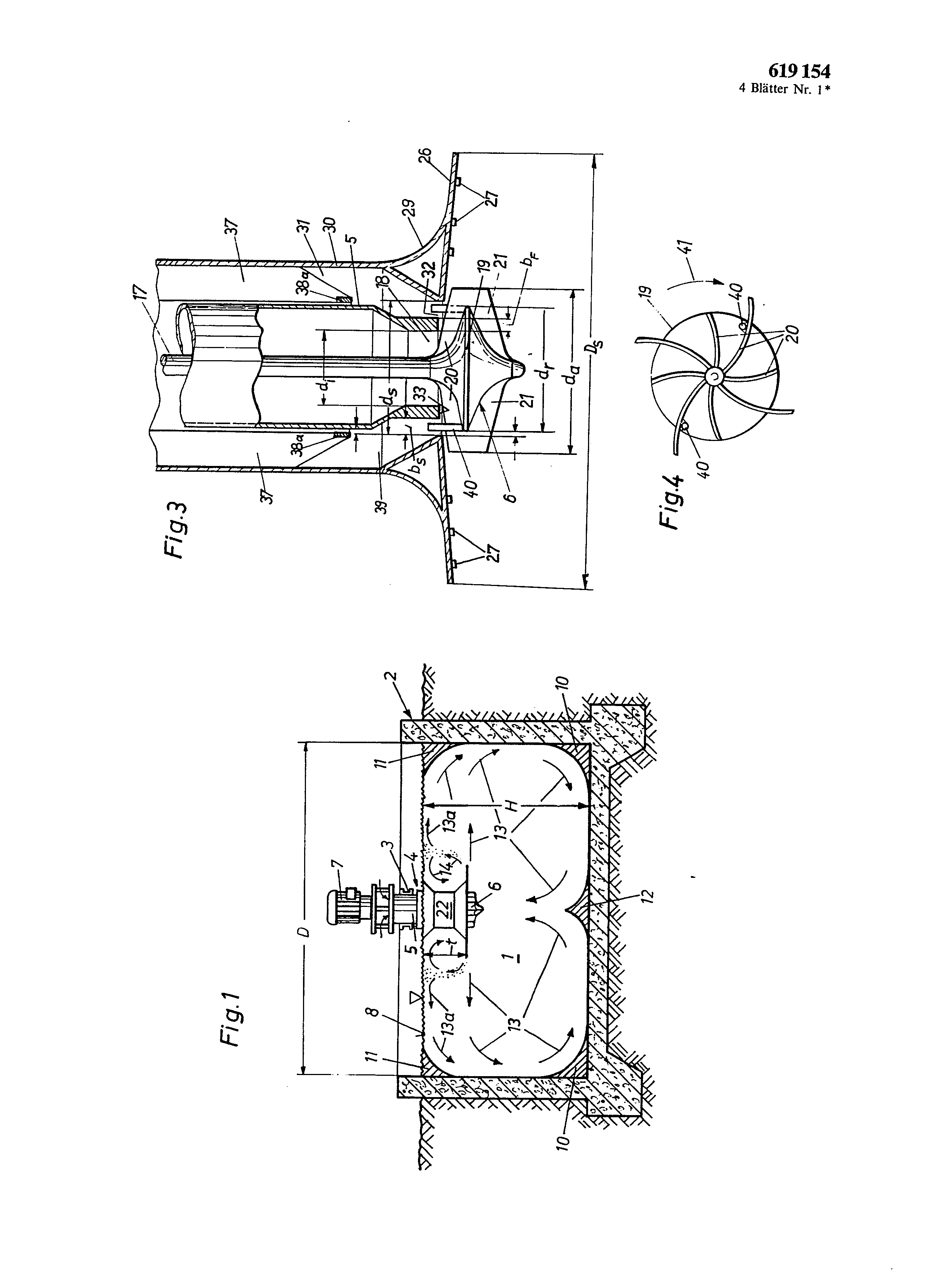
Fig. 1 an overview cross section by a tank with an aeration mechanism according to invention, Fig. 2 an increased cross section by an aeration mechanism similarly Fig. I, Fig. 3 far increased, vertical profile by the lower part of an aeration mechanism according to invention, Fig. 4 an axial plan view on the top side of the rotor of the mechanism of Fig. 3, Fig. 5 a vertical cutaway view of a further execution form of a Begasungseinriehtung after the invention, Fig. 6 a gas-lateral axial opinion of a rotor for ëine Begasungseinriehtung according to invention, Fig. 7 a schematized cutout side view swimming of an arranged aeration mechanism after the invention with absenkund raisable aeration unit and Fig. 8 a plan view on the arrangement of Fig. 7.
A liquid substrate 1, e.g. liquid manure, is in the example of the Fig. , preferably containers 2 round 1 in the aerodynamically cleanly arranged filled in. Suitably would be also a square container with abeschrãgten or rounded corners. Over a bridge 3 formed from steel girders centrically an aerator 4 arranged with immersion tube 5 is, rotor 6 and driving motor 7 in the container 2. The container 2 can be about halfsquare in the cross section, so that the diameter is about twice as large D like the Füllhöhe of H with enterprise. On the fluid level 8 kannje according to kind of the substrate 1 a foam cover or a floating cover 9 (Fig. 2) in an educated manner its. Submergence t of the aerator 4 into the liquid amounts to about a quarter of the Fûllhöhe of H. by this arrangement -- H ------'D/2 and t H/4 -- does not result particularly favorable StrömungsverhältDamit itself in this cross-section contraction Verstopfun5o nit, so that it is possible, the circulation with smallest towards to form can and a Vordrall of the air flow energy expenditure optimally maintain themselves here. The channel in its last section up to the out-flowing RingsÇhlitz appropriately by distance holding, special fittings and such are additional are kept free in to train can. The Sanberhaltung of the annular gap and the training of a Vordralls e.g. through in-extending clearing finger becomes begünstigt. on the top side of the wheel-center disk body of the rotor axially upward into the annular gap
The special fittings distance-holding in the foam gutter-pipe can be in such a manner arranged that they favour a spin formation of air. In order conventional-proves forces hanging up from sheet metals to interception of rougher contaminants or pool parts in the foam gutter-pipe to avoid, can be intended that the distance owners in each case as itself noly-break over the axial length of the support extending Bieche trained sind.
Also with a Belüftungseinñchtung with foam gutter-pipe a radially standing blister distribution screen is arranged around the opening and the annular gap. If it is go-aged by the Sehaumfalirohr, then the annular gap leaves itself freely arranged by inserting oaths corner ranges at the ground and in play gel proximity of Verdrängerkörper 10 and/or 11, which cause a low-loss flow diversion. Furthermore a rotationally symmetric displacement body 12 arranged of Kegeloder Hyperboloidform is, in order to favour as low-loss a detour of a centripetal, horizontal liquid movement as possible into an upward-arranged current at the ground underneath the rotor 6 in the basin center. In the basin 2 of the represented cross section from there essentially two rotationally symmetric liquid rollers are formed, which are pushed ago by the rotor 6, i.e. a basic roller (flow arrows 13), itself constantly with an oxygen-rich, Flüssigkeitsströmnng near the surface and centrifugal (flow arrows 13a) united, and a smaller Oberwalze (flow arrows 14), those by ascending blisters of registered gas lively wird.
With the explained arrangement one obtains a particularly high entry achievement of air and thus from oxygen into 619,154 the substrate 1 by as low-loss circulation and a mixture of all basin contents as possible in such a manner that particularly the liquid areas well attainable with gas bubbles with less well attainable zones constantly in contact brought werden.
During air supply time the local oxygen gradient is kept very small within the substrate 1, so that locally a partial saturation does not enter and in other place partly still another strong deficit at oxygen. The saturation time for all basin contents is shortened by circulation, mixing and Vergleichmässigung of the oxygen content, o i.e. the necessary drive power per quantity unit at registered and solved oxygen becomes smaller compared with a less good, more involving heavy losses mixture and circulation of basin contents after the state of the art. The basin organization and the arrangement of the Beiüftungseinrichtung 4 within the container 2 are thus for the technological efficiency with entscheidend.
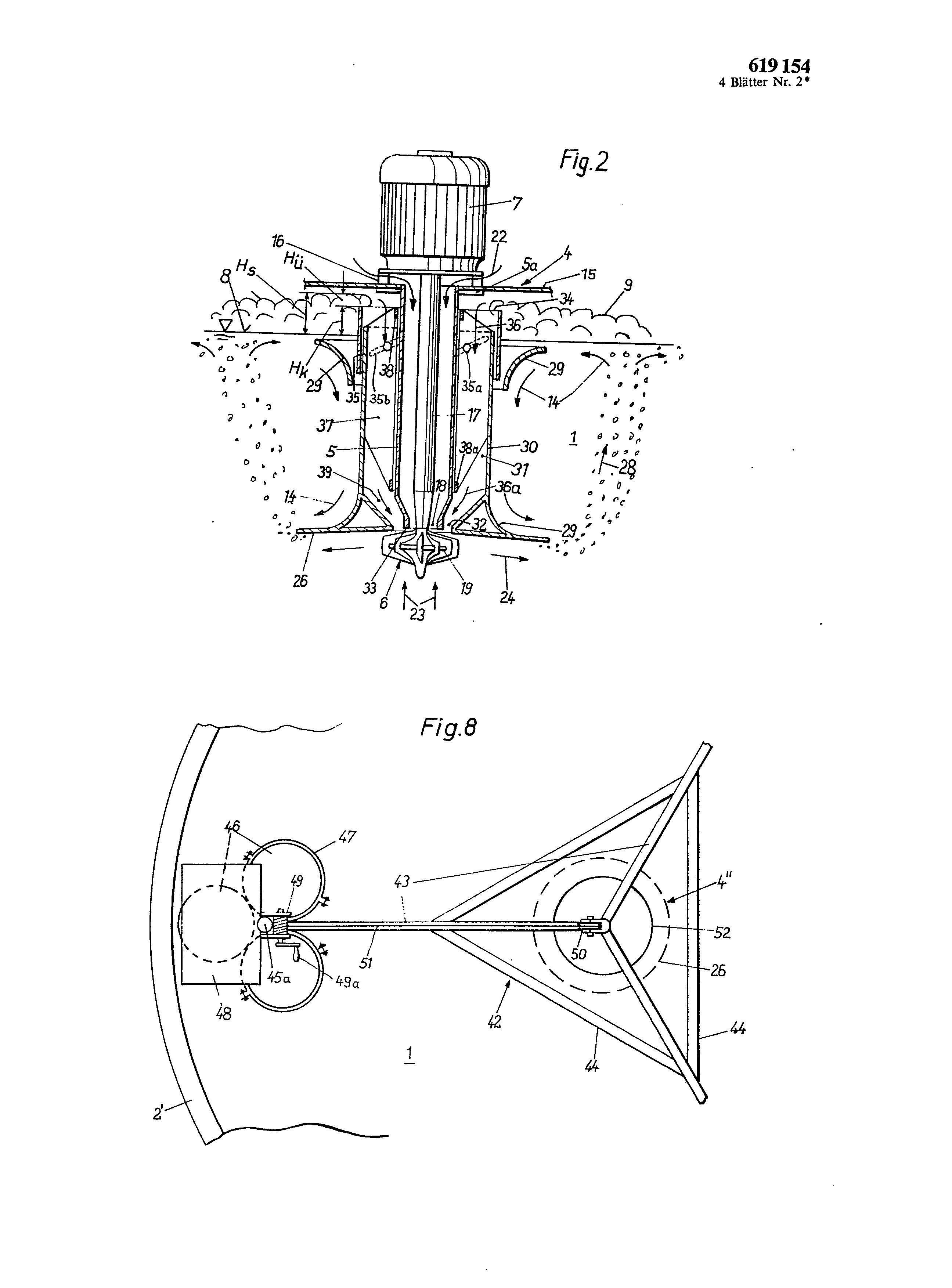
In Fig. 2 to 4 Belüftungseinriehtung shown 4 increases is fastened over spacer 16 to a platform 15, those for their part part of a Brückenoder of a swimming construction .ähnlich Fig. 7 and 8 to be can do. The mechanism 4 dives under the mirror 8 of a liquid in (here not drawn) a container. The blower 4 essentially consists of the immersion tube 5, which by means of a flange 5a to the platform 15 is fastened, the Antñebsmotor 7 with the immersion tube 5 interspersing drive shaft 17 and to their end fastened, underneath the immersion tube 5 the lying rotor 6.
The immersion tube 5 communicated above with air over the platform 15 and ends down with as a small amount of axial play at a air-lateral blading of the Retors as possible 6. to the latter the course-turned end of the immersion tube 5 forms from there an opening 18.
The wave 17 can be as far as possible vibration-free stored in the engine 7. Alternatively or additionally a support bearing 17a can be intended, lateral excursions of the wave 17 not possibly macht. near the lower end of the wave 17
The rotor 6 consists 19 attached shovels of a wheel-center disk body I9 with aerodynamically cleanly more curved eberund lower surface as well as out on both sides the wheel-center disk body, of which the shovels 20 on the top side of the wheel-center disk body 19 air sucked in above the platform 15 and the shovels 21 on the lower surface of the wheel-center disk body 19 liquid promote (substrate 1). The number of shovels 20 on the top side is larger than those of the shovels 21 on the lower surface. As far as possible the upper-lateral and under-lateral shovels 20, 21 are congruently arranged. The liquid shovels 21 and those Luftbzw. (ììasschaufeln 20, which lie with first congruently, extends over the outside diameter dr the wheel-center disk body I9 outside up to a diameter there, whereby the outside delimitation of the Retors 6 is formed (Fig. 3).
The rotor 6 in circulation transferred by the Antñebsmotor 7 sucks through the opening 18 and the immersion tube 5 air from the atmosphere on (flow arrows 22); the rotor 6 sucks at the same time axially from the depth of the basin 2 liquid 1 on (flow arrows 23). Both media, air and liquid, are dispersed at the rotor withdrawal and ejected radially outward (flow arrows 24). Over a broad screen 26 is arranged the rotor 6 around, at its lower surface the turbulent current 24 first entlangíìiesst, whereby the air/liquid mixture is fine-bubble dispersed and due to the turbulence an intensive phase boundary exchange stattfindet.
The screen 26 prevents the dispersed bubbles first from ascending and holds it with the centrifugally ejected liquid over a long distance away in turbulent Kentakt. Within the radial range of the screen 26 the liquid ejected by the rotor 6 has still another a high Strömungsgesehwindigkeit and turbulence, which prevents a Blasenkoaleszenz. Registered air remains fine-bubble and in small power in the Strõmungsflüssigkeit; the gas lift is thereby much geñng.
The screen 26 may be to large however not and does not see themselves not into such ranges inside extending, in those the liquid flow under certain minimum speed values slowed down; otherwise it would come at the edge of the screen 26 nevertheless still to rough blistering and to a back pressure of liquid, which the whole rolling over movement in the basin 2 unfavorably do not only affect, but also a strong impairment of the transition of the blisters to the liquid brings würde.
In addition the gas registered by the rotor 6 would be present in so large power under the screen 26 during back pressure and rough blistering that a Auftñeb would develop, which could raise swimming Bdüftungseinriehtungen 4 and impair their Lagestabilirät, in order to meet these lack is such a calculation intended that the speed height of the Schlrmaustrittsströmung somewhat smaller than submergence t of the rotor 6 ist.
Thus the registered driving power is used particularly favorably, and the liquid within the range of the screen 26 flows with security still sufficiently fast, in order to prevent a rough blistering. The correctly measured screen offers the further advantage of an intensive phase boundary exchange with fine-bubble dispersed registered air in the cooperation with the flow turbulence within the substrate I. The rapid phase boundary renewal favours an oxygen transition, by preventing the fast gas saturation, which would slow otherwise the further oxygen admission down in the directly neighbouring boundary layer of the liquid. This turbulence is still promoted or maintained at least despite flow slowing down, if at the lower surface of the screen 26 unstablenesses 27 (Fig. 3), e.g. in the form of small pins, burls or such are arranged, their height itself by the blister diameters bestimmt.
At the outer circumference of the blister screen 26 an ascending Blasenschleier due to the Gasauftñebes (flow arrows 28) forms. This upstream 28 causes a flow roller surrounding circularly the Bdüftungseinrichtung 4 (arrows 14) above the screen 26. By installation of flowfavouring Umlenld'lïehen 29 (Fig. 2 and 3) underneath the water surface 8 and at the transient area into the screen 26 is kept particularly small the flow losses of this liquid roller 14, whereby keep the kinetic energy in-carried by the Blasenschleier 28 into the substrate I large bleibt.
Depending upon kind of the too begasenden liquid 1 the ascending Blasenschleier 28 forms more or less strongly shame. To the delimitation of the power of such a foam cover 9 (Fig. 2) can be for the feedback reliable in service of the foam into the substrate 1 concentrically around the immersion tube 5 around a foam gutter-pipe 30 arranged, which forms a circular foam drop channel 31 together with the immersion tube 5 and which flows over an annular gap 32 surrounding the opening 18 in the directly effective range on the top side of the rotor 6. A POngspalt 33 with a certain radial Mindestbreite, present between Ringsehlitz 32 and opening 18, BF ensures a sufficient suction height for dle air sucked in by the immersion tube. The outside diameter CH of the annular gap 32 is so limited that this extends only into ranges inside, in which a suction effect of the rotor 6 is still present. Also the opening I8 is in such a manner limited that in its range the negative pressure produced by the blower 4 is larger than the counter-pressure, which submergence t of the rotor 6 entspricht.
The represented arrangement prevents that in the SehaumfalIrohr 30 a fluid level could be formed, since crossing water and foam are exhausted immediately by the rotor 6. The radial width bs the Ringsehlitzes 32 is for an unhindered depresses the foam laid out. The annular gap 32 extends between the Ansaugöffnnng 18 bzw.
the annular gap 33 at the lower end the immersion tube 5 and the screen 26 at the lower end the foam gutter-pipe 30, that therefore s the mounting plate for the blister screen 26 bildet.
The immersion tube 5 exceeds with its upper end over the water level 8 and forms a foam drop edge 34 for the foam 9. the assault height Hk of the foam drop edge 34 is so adaptable power H of the foam cover there that a l0 certain projection Hü of the Sehaumes 9 over the edge 34 prevents the formation of foam bridges in the circular foam drop channel 31. In the remark example in accordance with Fig. 2 are intended to this betriebsgemässen adjustment of the Höhw Hk of the foam drop edge 34 a foam drop ring 35, which is axially mobile by Drehbewei5 gung opposite the SchaumfaUrohr 30, for example as staybolts 35a part in diagonal or schraubenlinienförmig running long holes a 35b of the other part eingreifen.
With very strongly H/issigkeiten polluted by suspended materials and foam covers, which bring a strong Schmutzfraeht into the foam gutter-pipe (arrows 36), could be well adjustable the ring 35 and thus the projection Hü of the foam drop edge 34 after certain Betriebsund contamination duration no longer, if the sliding surfaces with dirt added themselves to and an adjustment movement to make more difficult. For these cases is in Fig. 7 and 8 represented construction intended, those further down describes wird.
To be removed for maintenance an axial attachment of the foam gutter-pipe 30 is to be only eliminated and the rotor 6. Afterwards the SchaamfaUrohr can do 30 if necessary axially taken off from the immersion tube 5 werden.
At the inside of the foam gutter-pipe 30 Bieche radialdistance-holding 37 is welded, which ends radially inward before the immersion tube 5 freely. Only to their upper and lower 3s ends are against each other stabilized the distance plates 37 by Versteifungsringe 38, 38a. The upper Versteifungsring 38 can be with clamping screws provided, by the foam gutter-pipe 30 and the screen 26 in the correct axial position opposite the immersion tube 5 and the annular gap 33 axially and in circumferential direction fixes itself leave/>
In consideration of the axial relocatability of the foam drop construction on the immersion tube 5 also the outside diameter is dz the Ringschiitzes 32, which is equal the inside diameter of the blister screen 36, somewhat more largely than the Aussendurehmesser of the immersion tube 5. the distance owners 37 is nnterbrechungsfrei going through Bieche, which the incident foam no unnecessary Angriffsfläc] aen offers, at which carried along dirt could settle. The Bieche 37 can be schraubenlinienförmig connected, so that her by the Sehaumfalls0 the pipes through 30 angesangten air a Vordrall in the sense of the direction of rotation of the rotor 6 erteilen.
The last section 39 of the Schaunffallrohres 30 present before the annular gap 32, in which the circular cross section of the Schaumfallkanals31 of aufden cross section the annular gap 32 tapers itself ss, is kept free of installations. By this cross-section contraction and flow acceleration accompanying with it (arrows 36a) a spin already introductory is strengthened, without any installations impair it into this spin before area 39 könnten.
The training of such VordaUs still favoured by of the rotor 6 ago axially into the annular gap 32 inside extending and it constantly keeping free Räumñnger 40. These are in such a way arranged at the outer circumference of the Radseheibenkörpers 19 of the rotor 6 that they sit on the side of a shovel 20 rear in Drehrichtnng 41, whereby them a completely small flow resistance bieten.
In the Fig, 5 and 6 another arrangement of the Erfìn619 154 dung is described. This remark example is simpler than the before-descriptive construction, since the Scbaumfallrohr can be void. Essentially horizontal conducting surfaces 53 and/or 54 at the air shovels 20 ' support the function of the blister screen 26 at the aerator 4 ' in favourable Weise.
One recognizes in Fig. 6 that at the gas shovels 20 ' axially extending conducting surfaces are arranged. In the upper half of Fig. 6 is short conducting surfaces 53 and -- as execution variant -- in the lower half of Fig. 6 extended conducting surfaces 54 drawn, which are in each case into the wheel-center disk body 19 of the rotor outstanding range of the gas shovels 20 '. The conducting surfaces 53 and/or 54 to extend see only on one side from the shovels 20 ' in direction of rotation 41 forward and do not reach not up to the neighbouring in each case shovel. A continuous opening (distance A) ensured that even rough mechanical impurities are through-torn by in such a way formed shovel channel, so that it remains always free by impurities. The free edge 55 of the conducting surfaces 53, 54 is in such a way arranged that each to any point 56 the outline drawn center jet includes 58 with the tangent 57 in this point a pointed angle OE. The edge 55 is fñr itself easily rejecting îestsetzendes material, thus it always remains free and voli wirksam.
The purpose of the short. Exists conducting surfaces 53 dañn not to let escape the gas drug along by the liquid flow in direction of arrow 24 and/or 41 by lift forces immediately again to force upon but to the dispersed gas vesicles at least for a somewhat longer distance the direction of the radial flow 24. Thereby the time of contact in particular of very fine gas vesicles with the Flñssigkeit is increased and obtained during same drive power a better transition of the effective components in the sucked in gas, as 02 in air, CO2 in the Rauehgas or O3 in ozonisierter air. Besides the radial flow 24 is not pushed aside so strongly upward, so that they arrive more easily into layers less near the surface kann.
The time of contact of the gaseous and liquid media is still continued to increase by sickle-like extended conducting surfaces 54, as the river 24 more telleroder screen-like by a thin, nonporous river 25 enriched with gas bubbles is covered. Its large HorizontaIimpuls prevents itself extracting the gas bubbles from the dispersion stream 24 moving under it. Cover Rome 25 spreading with large speed can be broken through only by the gas bubbles, if their climbing strength is larger than the Horizontalimpuls of the dñnnen Abdeckstromes.
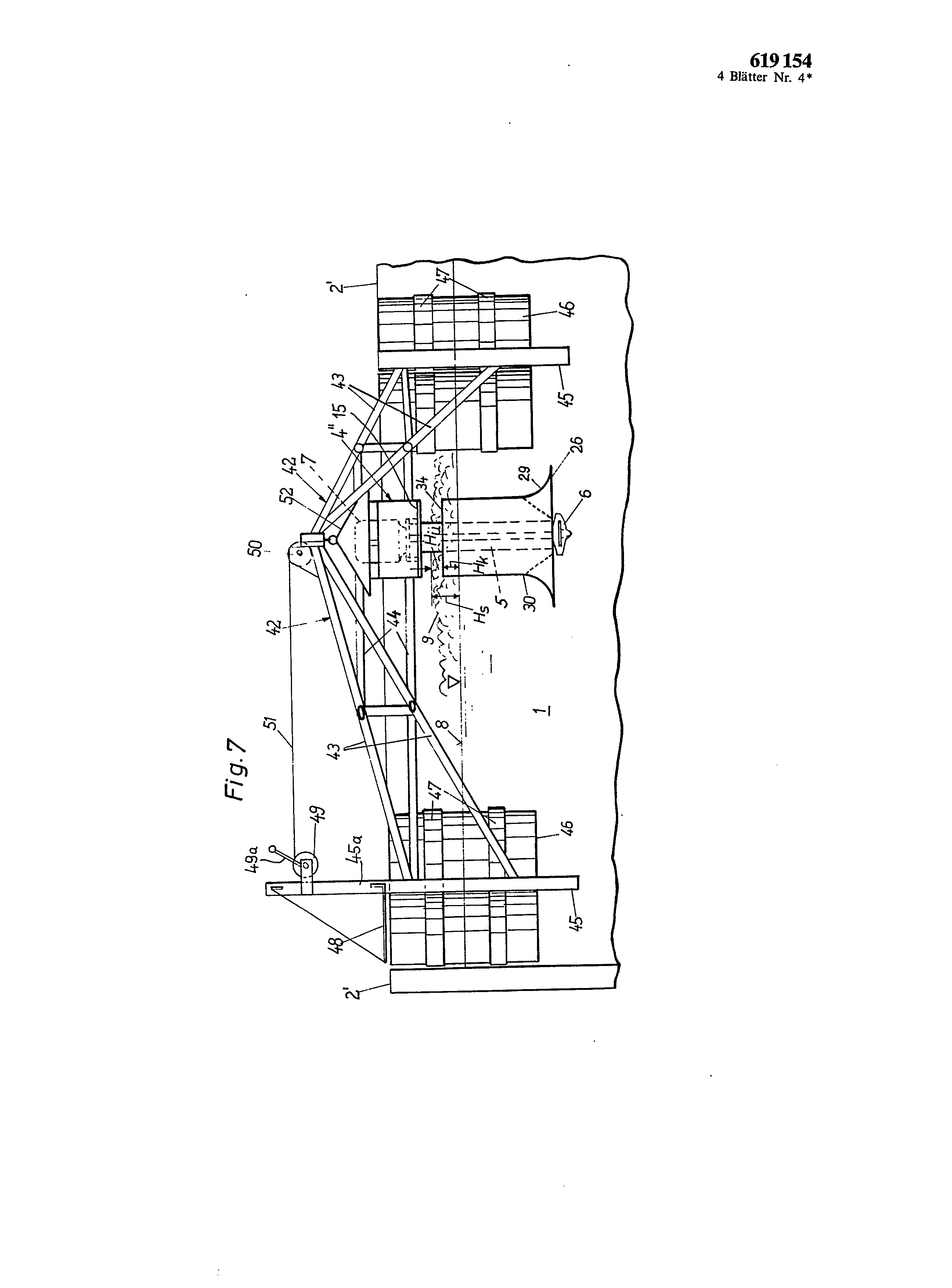
For strongly soiling F1iissigkeiten with strongly changing foaming power training and a suspension of the aeration unit are 4 " in accordance with the remark example of Fig. 7 and 8 appropriately. On a float construction 42 the aeration unit existing made of driving motor 7, rotor 6, immersion tube 5, foam gutter-pipe 30 and Schrim 26 is höhenverstellbar hung up 4 " over a changeable push pull cable 49, 50, 51. The float construction 42 can to each other exhibit three arms 43 arranged in the angle of for instance 120°, which are mutually supported by props or pipes 44 and reinforced. The arms 43 are arranged at Standrohren 45, which can be enough downward to underneath the rotor 6 in its highest position, so that the whole mechanism can be turned off on the dry one without damage of the rotor 6 on the Standrohren 45. At the latters in each case three flotation chambers 46 fastened with tires 47 are. The flotation chambers 46 can be well sealed Kunststoffässer” like it to the transport of Flñssigkeiten or such to be used. In particular with application for strongly soiling liquids 1 and/or strongly soiling foam covers 9 large flotation chamber volumes are important, because the Sehwimmkörper loads 46 in the enterprise with a high Sehmutzfracht werden.
The Standrohr 45 one the arm 43 is upward 619,154 extended. At this extension 45a a console is fastened with a Standfläehe 48 as well as one e.g. by a crank handle 49a to betãtigende rope hoist 49. In the center of the arrangement, where the three jib heads meet, one is to rope [winds 49 arranged role of 50 arranged, across which is led from the Seilwiude $eilzug 51. On this the aeration unit 4 hangs " over an accordingly stably built rain protection housing 52.
By raising and/or lowering of the aeration unit 4# by means of the rope hoist 49 the height of Hk of the Sehaumfallkante 34 the Mäehtigkeit H of the Sehaumdeeke 9 can be adapted in each case and so l0 the optimal projection Hü be adjusted. With mirror heights Sehwenkungen remains this projection Hü owing to the float construction 42. Only if the Sehäumverhalten of the too begasenden liquid ãndert itself and accordingly varies from there foam thickness power H, must be varñert the altitude the housing 52 regarding the mirror height 8. The invention considers also means, with which a simultaneous change of submergence t of the aeration unit 4# can be compensated in simple way, e.g. by elevation adjustment barness of the aeration unit 4 " relative to the housing 52.
Rohrund rotor construction of the remark example of Fig. 5 and 6 is in principle with the arrangements after Fig. 1 to 4 or Fig. 7 and 8 likewise applicably. Turned around the latter arrangement for elevatormobile mounting plate also with the simplified Begasungseindchtung 4 ' geeignet.
R4 of sheets designs of 619,154 4 pages No. 1 * EN The invention relates to a circulation gas-liquid mixer with a rotor (6) which is submerged in the liquid, has vanes on both sides, draws in gas on its upper side via a plunge pipe (5), draws in liquid at its underside, and disperses both media at the rotor outlet. The rotor, in the manner of a double-entry, radially traversed pump or blower rotor, has a closed wheel disc body (19), which carries vanes (20, 21) on both sides and has a diameter (dr) which is greater than the internal diameter (di) of the plunge pipe. The plunge pipe (5) is surrounded, in the vicinity of the rotor, by a screen (26) which runs perpendicular to the axis and whose external diameter (DS) is substantially greater than the external diameter of the rotor (da). On the inside, the screen (26) extends continuously, both axially and radially, as far as the top side rotor vanes (20) without touching them. This construction permits low-energy gas introduction. The gas passes into the liquid with a high velocity through a narrow slit at the circumference of the wheel disc body, thus producing fine gas bubbles. The screen causes strong turbulence of the dispersion and prevents said gas bubbles from coalescing and rising, as a result of which bubble dispersion over a large volume is achieved. <IMAGE> 1-device for the gasification of liquids, with a rotor immersed completely in the liquid, set in motion by a driving force, effective to produce the movement of the liquid, which on the side facing the surface, the liquid drawn up by a dip tube a gas, preferably air, and on the opposite side of the rotor of the liquid from the environment of the rotor, and which, in the style of a pump wheel or double entry fan is radially traversed by the current, has a disc wheel with displacement blades disposed on both sides of front, for the gas and the liquid, for the spread of the two media, and the dip tube is provided with in the area of its lower end facing the rotor a suction opening, and a screen surrounding the suction opening and disposed at least approximately perpendicular to the axis, characterized by the fact that the screen extends axially and radially as close as possible to the rotor, or is formed by same. 2-A device according to claim 1, characterized in that the free diameter of the suction opening is smaller than the diameter of the wheel disc of the rotor and is about 0.2 to 0.6 times equal to the outer diameter of the rotor, the smaller factors to be used for the revolutions small, and the factors larger for larger the rotational speeds. 3-A device according to claim 1 or 2, characterized in that the outer diameter of the screen has a dimension such that the output speed of the screen of the liquid stream set in motion by the rotor and to slowing outwardly produces turbulence preventing coalescence gas bubbles dispersed. 4-Device according to one of claims 1 to 3, characterized in that the depth of immersion is larger than the degree of flow velocity crimped of the screen. 5-Device according to one of claims 1 to 4, characterized in that on the bottom side of the, in the area located radially outside the rotor, there is provided a certain number of pieces of discontinuity (27) whose axial extension corresponds approximately to the diameter of the gas bubbles. 6-A device according to claim 5, characterized in that the discontinuities consist of parts arranged concentrically to the rotor, ring-shaped, preferably by degrees backward, or in the form of bosses, bolts, andc. 7-Device according to one of the claims 6, characterized in that on the axial surfaces of the blades is provided, at least in the region radially surmounting the wheel disc, guide surfaces extending perpendicular to the axis. S-A device according to claim 7, characterized in that the guide surfaces are, in the circumferential direction, shorter than the interval between two neighbouring blades. 9-A device according to claim 7 or 8, characterized in that the guide surfaces extend forwardly, in the direction of rotation of the rotor. 10-Device according to one of claims 7 to S, characterized in that the guide surfaces are, preferably sickle-shaped, extended radially outward beyond the blade tips. 11-Device according to one of claims 7 to lO , characterized in that the free edge of the guiding faces forms an acute angle with a radius driven at its center to the corresponding contour point. 12- ïlune Device according to of claims 1 to 11, characterized in that the wheel disc (19), as well as a displacement body bladeless, rotationally symmetric, present in radial section a contour favorable to the current. 13-Device according to one of claims 1 to 12, characterized in that about the plunger pipe there is provided a drop tube of foam forming opposite the intake duct air or gas of the dip tube a deflection channel to the foam or floating matters. 14-A device according to claim 13, characterized in that the channel surrounded by the foam drop tube opens into a circular slot surrounding the suction opening of the dip tube, on the upper side of the rotor, in the intake region. 15-A device according to claim 13 or 14, characterized in that between the outer edge of the suction opening and the inner edge of the annular gap it is an annular collar (33) extending at least approximately perpendicular to the axis, and whose radial width corresponds to about 0.1 times the outer diameter of the rotor. 16-Device according to any one of claims 13 to 15, characterized in that the channel (31) tapers towards the rotor, at least in the region close to the outlet. 17- îfiune Device according to of claims 13 to 16, characterized in that the upper end of the drop tube foam forming an edge of foam drop extends to above the surface of the liquid. 18-A device according to claim 17, characterized by the fact that the edge of the falling drop tube of foam is formed so as to be adjustable in height relative to the liquid level, independent of the height position of the other parts of the device. 19-Device according to any one of claims 14 to 18, characterized by the fact that the outside diameter of the annular gap corresponds at most to 0.8 times the outer diameter of the rotor. 20-Device according to any one of claims 14 to 19, characterized in that the width of the annular gap, measured in the radial direction at its rotor-side end, corresponds approximately to 0.1 times the outer diameter of the rotor. 21-Device according to any one of claims 13 to 20, characterized in that the channel (31) is, in its last part, to its termination to the annular gap, free of struts, components, andc. 22-Device according to any one of claims 13 to 21, characterized in that spacers provided in the top part of the drop tube of foam have a shape with faces causing the twist of the current, which produce pretwist corresponding to the direction of rotation of the rotor in gas aspirated into the drop tube foam. 23-Device according to any one of claims 13 to 22, characterized in that on the upper side of the wheel disc rotor, there are provided-pegged scraping extending to the. high in the annular gap. 24-A device according to claim 23, characterized by the fact that ' the lugs scraping are arranged at the periphery of the wheel disc of the rotor. 25-A device according to claim 23 or 24, characterized in that the fins are each placed near scraping d * a blade of movement of the gas, on its rear side in the direction of rotation. 26-Device according to any one of claims 13 to 25, characterized in that the screen ear and at least one body current déviaticn c. e are attached to the foam tube. 27-Device according to any one of claims 13 à^6 , characterized in that the outer diameter of the annular annuity is a little larger than the outer diameter of the dip tube. 2S-Device according to any one of claims 13 to 27, characterized in that the spacers (37) between the drop tube and foam dip tube are set solely to one dies two tubes, preferably the inner side of the drop tube foam, and that these distance pieces are adjusted, at their other free end, slidably to the other tube. 29-Device according to any one of claims 13 to 23, characterized in that the free ends of the spacers are, for their provide rigidity, provided with circles or tires. 30-Device according to any one of claims 13 to 29, characterized in that the drop tube foam, that holds the display screen, is constituted by separate part, removable by axial sliding on the dip tube. 31-Device according to any one of claims 13 to 30, characterized in that the spacers are each constituted by a sheet s * arranged continuously over the axial length of the support. 32-Device according to one of claims 1 to 31, with a float which floats on the liquid to be gasified, and a platform, a frame device or similar, characterized in that the device as a whole can be ' raised and lowered relatively to the float. 33-A device according to claim 32, characterized in that on the float there is provided a winch, and a high place of the gasification device, a deflection pulley for the cable extending from the winch and wearing the device. 34-Device according to one of claims 1 to 33, characterized in that for the line without loss of the circulating stream, the receptacle that receives the liquid to be gasified has a favorable shape to the current, -or is provided with accessories favorable to the current0 35-Device according to one of claims 1 to 34" characterized in that the depth (H) of the wet container is half as large as a downhole measurements of B diameter or the length of a side of the fan (2). 36-A device according to claim 35" characterized by in that the depth of immersion (t) of the rotor is equal to about 1/3 to 1/5 "preferably 1/4 of the wetted depth of the container" 37-Device according to any one of claims 34 to 36 "characterized by the fact that the receptacle is of a circular shape in plane or approaching this form" 38-Device according to any one of claims 13 to 37" characterized by the fact that the passage of the dip tube and of the drop tube of foam in the screen is provided, in axial section, of deflecting surfaces favorable to the current. 39-Device according to any one of claims 13 to 39" characterized in that in the immediate proximity of the surface, the edge of the tank, near the immersion pipe or the drop tube of foam, there are provided screens or deflection surfaces, of displacement bodies to inclined or curved face. 40-Device according to any one of claims 13 to 39, characterized in that the periphery of the container, in the region of the bottom, there are provided displacement body inclined with respect to the vertical or curved, displays or deflecting surfaces. 41-A device according to claim 40, characterized by in that the displacer is positioned at the position of plane of the rotor, at the bottom of the container and is formed in a manner to obtain current rotation and symmetrical to the"