DRESS PRESENTATION RACK.
PATENT CLAIM 1st Kleiderprhsentiergestell with a device for fastening a h6henverstellbaren carrying bar (3) fiir the admission yon poster retaining means (4) characterized in a Stiitzenteil (1, 10) of the Priisentiergestelles, by the fact that the carrying bar mounting device (2) in a Aufnahme6ffnung (l',] 0 ') of the Stiitzenteils (l, 10) strammsitzend an assigned tap part (of 6, 12) with a central mounting hole (5) ffir the carrying bar O) and one with the tap part (of 6, 12) connected, the carrying bar (3) in the clamping interference springily embracing clamping range (6 ", 6 "; 12 ', 12 ") aufweist.
2. Rack according to requirement 1, by the fact characterized that the tap part (6, 12) with the mounting device (2) in the Aufnahme6ffnung (1 ", 10 ") centering interference means (7, 14) provides ist.
3. Rack according to requirement 1 or 2, thus gekennzeiehnet that the clamping range (6 ', 6 "; 12 ', 12 ") Liingsschlitze going through radially with a majority fibre its whole Liinge more being enough, to produce (9, 17) is provided, in order clamping device-like Eingriffder a stopped Ringsegmente on the Oberfl che of the carrying bar (3), and that the pressure strength erh6hender locking collar (s) put to fibre the Rinsegmente ist.
4. Rack according to requirement I or 3, by the fact characterized that the tap part (6, 12) and the clamping range (6 ', 6 "; 12 ', 12 ") as einstfiekiger K6rper plastic helastischen from a z formed sind.
Rack after one the Anspriiche Ibis 4, by the fact characterized that at the free end of the tap part (6, 12) a Siiulenabdeckkappe (8, 16) angeformt ist.
6. Rack after one the Anspriiche 1 to 5, by the fact characterized that with a Ausrundung or with a conical verjiingten portion (3 ') it provides the free end of the carrying bar ist.
The available invention refers to a Kleiderpriisentiergestell after the generic term of the patent claim 1.
In Verkaufsriiumen set up Kleiderpdisentiergestelle is multiple with mechanisms for attachment or the holding of Preisund/or Gr6ssenangaben-Anschriften or - posters provide. So that the addresses or posters around the Priisentiergestell readable harm practically approximately, the retaining mechanisms preferably become on bars or other load carrying means fastens and with it the Informationsfliichen on a HShe brought, where they are unhindered visible. The carrying bars and such a thing, are befesfigt usually with Klemmund screwing devices on rack iulen, arms or cross beams and form hiiufig a more or less adapted accessory to the Kleiderpriisentiergestell ausgeriisteten thereby. The danger of the occurrence yon pressure points and Kratzem, abgebliitterter color or other Schutziiberziige at the rack and/or the carrying bars is thus substantial. A further danger consists of it that preferably with the disassembly that often] calibrates aufund degradable racks those relatively diinnen and mechanically few widerstandsf higen poster seaweeds to be bent and thus fiir the further use ausfallen.
The task of the invention exists thus in the Schaflung of a Kleiderpriisentiergestells with one at this permanently existing photograph device f r a poster carrying bar, clampinginterference-held into which latter h6henverstellbar and through ist.
Invention in accordance with sse Lfsung this task is defined by the patent claim 1. Ausfiihrungsformen of it result from abh the ingigen Anspri.ichen 2 to 6.
The advantage of the erfindungsgemiissen L6sungsvorschlages s consists of it that the poster carrying bar without Betiitigung is yon Schraubund clamping members to the rack to fasten and to this easily into arbitrary H6henlagen bringable, with the disassembly of the rack without tool yore bezfiglichen place-hurries to be taken off can, and the danger eil0 of ner Oberfliiehenhesch idigung praktiseh impossible ist.
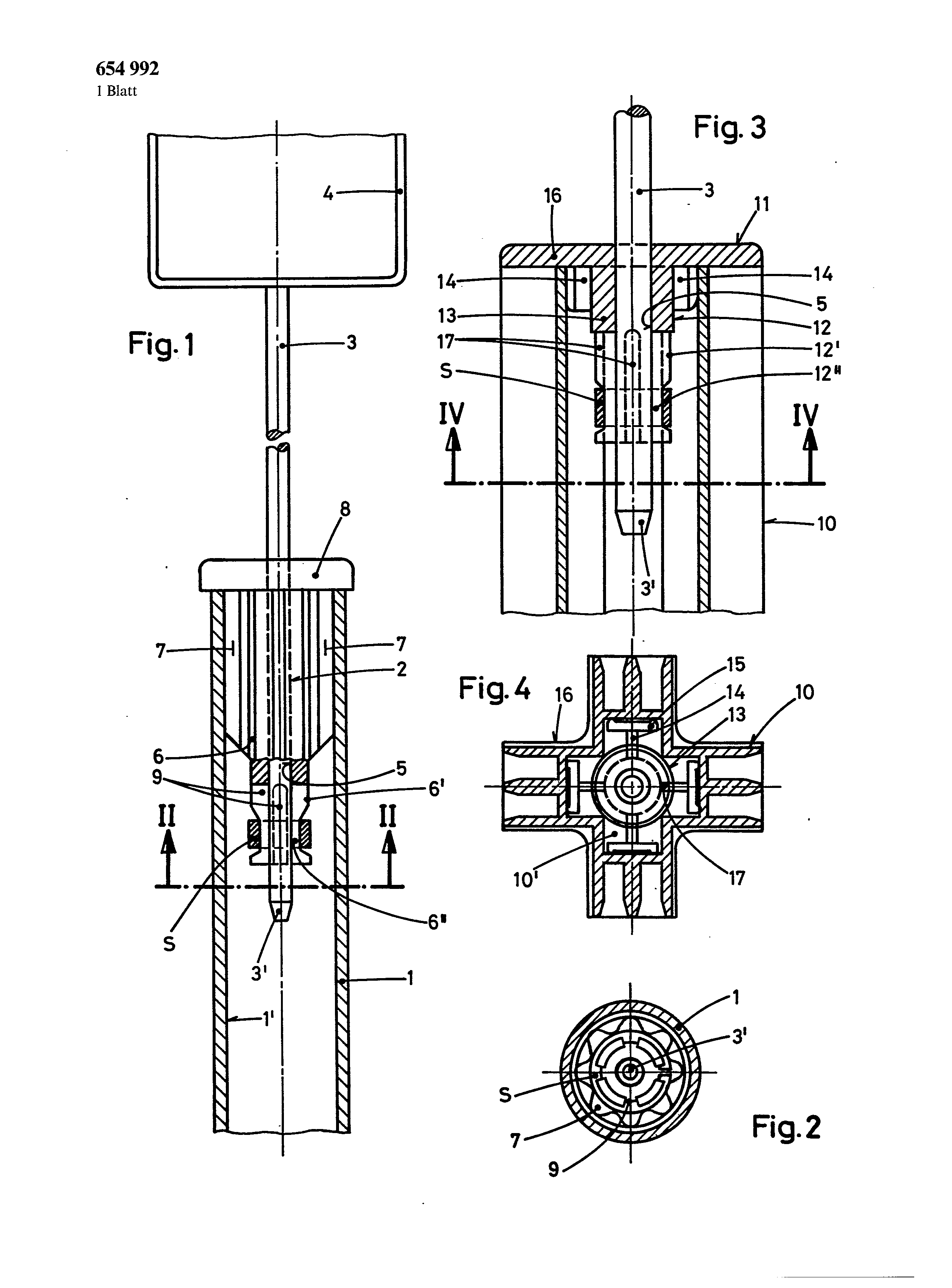
The invention is below descriptive on the basis the design for example. In the design shows:
Fig. 1 the attachment of a poster carrying bar inside a rohrf6rmigen. GestelltragsSule in the vertical cut, Fig. 2 an opinion of the mounting device in line of sight II-II in Fig. 1, Fig. 3 a carrying bar mounting device inside a crossing rising up school in the vertical cut, and Fig. 4 an opinion of the mounting device in line of sight IV-IV in Fig. 3.
The Ausfiihrungsform after the Fig. 1 and 2 shows a Rundrohrsiiule 1 of a Kleiderpriisentiergestells, into whose upper end a poster carrying bar mounting device 2 is inserted strammsitzend. The poster carrying bar 3, which for example 4 at its obeten end exhibits, sits central in the mounting hole of the carrying bar mounting device 2. the lower carrying rod end 3 ' is arranged for example by a final from roundness or a Endverjfingung in such a way that the bar 3 without centring difficulties into the mounting hole 5 of the mounting device 2 einfiirbar ist.
The carrying bar mounting device 2 exhibits a 1iinglichen tap part of 6, the fibre a part of its Liinge is with fullly at the wall of the Aufnahme6ffnung 1 " in the Siiule 1 lying close Fiihrungsund clamping ribs 7 provided, which center the Befestigungsvorfichtung 2 in the Rundrohrsiiule 1. The upper end of the tap part of 6 can be provided with a S iulenabdeckkappe 8, which can be formed as decorative Siiulenabsehluss. The lower tap section is verjiingt in two stages, whereby the upper stage 6 exhibits " a diameter, which is somewhat smaller than the main diameter of the tap part 6, and the lower stage is more dinner 6 " around that measure than the upper stage 6 ", which is necessary for the protection of a locking collar S against dropping from the lower tap section. The lower tap section is provided with radially going through Liingsschlitzen 9, the fibre a substantial part of its Liinge richen and a flexible clamping range for suspension reading tables holding the poster seaweeds 3 at the carrying bar mounting device 2 fesflegen, the Fiihrungsund Klemmbereieh saint S iulenabdeckkappe 8 of the carrying bar mounting device 2 is einstiiekig alas a z ihelastischen and/or appropriately flexible seh] agfesten plastic-manufactured, and the locking collar S preferably consists of steel or Bronze.
The Fig, 3 and 4 show the Gesta] tung eincr carrying bar mounting device 11 in application with a typisehen Kreuztragsiiule 1 0. The poster carrying bar and their mounting hole in the mounting device 11 are with the same reference numbers 3 and 5 as in the first Ausffihrungsbeispiel hezeichnet.
The again liingliche tap part of 12 of the mounting device 11 exhibits one in its highest (Fiihrungs) part at least angeniihert cylindrical section] 3, whose diameter is aligned zweckmiissig to the diagonal distance of the substituting hitting a corner edges in the cavity 10 ' of the Kreuzs iulenprofils, so that the section 13 rests fullly against these edges. Thus these hitting a corner edges can be used as a centring aid of the mounting device. At the obenliegenden cylindrical Absehnitt 13 radially which is away T-f6rmige Flfigelzentrierelemente 14 is attached, whose iusserst radially too lying Zentderbalken is at least co-ordinated with the Kreuzsehenkelbreite and to the Trags iule 10 form a Verdrehsieherung of the mounting device. The tap part of 12 can be, as already more friiher erl iutert, with a S iulenabdeekkappe 16 provided, with their lower surface the Flfigelzentderelemente 14 connected sind.
The lower tap section is again in two stages verjiingt. The upper stage 12 ' exhibits a diameter, 654,992 is somewhat smaller than the diameter of the highest cylindrical section 13. The lower stage 12 " is around that measure more dfinner than the upper stage 12 ', welehes to the Sieherung of a locking collar S against dropping from the lower tap section require-borrowed ist.
The lower tap section is further with radially going through L ingssehlitzen 17 provided, those practically fibre its whole Lfinge richen and a flexible clamping range for suspension reading tables holding the poster carrying bar 3 at the Tragstangenbefestigungsvorfichtuag 12 festlegen.
t5 s 1 sheet designs 654,992 1 sheet Fig, 1. ------3 8 [...] S i S IV 61 16 7, T Fig.4 16 10= 9 Fig. 3 IV Fig.2 2I A support part (1) of the clothes display rack is provided with a securing device (2) for a height-adjustable carrier-rod (3) for placard-holding means (4). The securing device (2) contains a plug part (6), which is inserted, with a tight fit, in the support part (1) and has a central bore (5) for the carrier-rod (3). Although this rod is securely held, by a clamping action, in a clamping zone (6', 6'') which is integrally connected to the plug part (6), it can nevertheless be shifted into virtually any desired axial position by applying a reasonable shifting force. 1. A clothes display rack comprising a height-adjustable carrier rod adapted for receiving placard-holding means on an upright support of the display rack and a device for securing the height-adjustable carrier rod, the device comprising, an elongated plug part having a substantially cylindrical upper portion and a lower end portion, said upper portion being adapted to be inserted tightly into a longitudinally directed central opening of the vertical support, said plug part having a central receiving bore for receiving said carrier rod and being provided with longitudinal clamping ribs on the surface thereof, the lower end portion of said plug part having a reduced diameter clamping zone in which said carrier rod is retainable in sliding engagement within said plug part. 2. A clothes display rack according to claim 1, wherein said clamping zone is provided with a plurality of radial longitudinal slots extending over its entire length and annular segments interposed therebetween, and in that said annular segments are interconnected through a clamping ring, which increases the pressure force onto the surface of said carrier rod. 3. A clothes display rack according to claim 1, wherein a column-cover cap is molded in one piece onto the upper end of said plug part. 4. A clothes display rack according to claim 1 wherein the clamping zone is provided with a plurality of radial slots passing through and extending over its entire length and annular segments being interposed therebetween to produce engagement of said annular segments in the manner of a split chuck on the surface of the carrier rod and a clamping ring being placed over the annular segments to increase a pressure-contact force. 5. A clothes display rack according to claim 1 wherein a free end of the carrier rod has a tapered configuration. 6. A clothes display rack according to the claim 1 wherein a free end of the carrier rod has a rounded off configuration.