Solar energy cooker - comprises plate mounted on stand and unit concentrating sun rays into bundle and direction them at plate
Beschmibung the subject of the invention is equipment for cooking under utilization of the solar power in accordance with the generic term of the patent claim 1.
Cooking by means of solar power is bekannt.
Equipment points Swiss patent specification No. 597,574 to cooking, with which by means of a paraboIoidischen hollow mirror the sunbeams are bundled and steered then from downside to a Pfannenträger arranged at a stand. With high position of the sun the hollow mirror is below the Kochstelle.
The well-known equipment for cooking by means of sunbeams has the disadvantage that the Hohispiegel is arranged underneath the Pfannenträgers always totally or partly and through to out-buy to go with liquid or fat splash is gotten dirty by the cook property. A contamination of the reflecting surface of the hollow mirror decreases its Funktionsfähigkeit.
In the further with the well-known equipment the only straight sunbeams bundled turned back to the lower surface of the Pfannenträgers and are used. With low position of the sun and therefore approximately vertically standing hollow mirror fall the bundled jets on the one hand in a pointed angle on in the Pfannenträger and as Kochplatte the serving pan held and on the other hand can only a Teli of the luminous beam be used, since the usable projected surface is smaller with diagonal idea than with approximately right Winkel.
The invention, how it is characterized in the Ansprûchen, does not solve the task to create equipment for cooking by means of sunbeams its device for the bundling of the sunbeams to the cook property dirty and with each position of the sun optimally usable ist.
Here the bundling of the parallel sunbeams coming to the earth is made by means of a collecting lens, those far away and by the Kochplatte placed ist.
In the further the Kochplatte is not only a Pfannenträger and/or a pan separates many more. It is a spatial l-section, its horizontal arranged thigh not only a Kochplatte, but also a heat accumulator ist.
Its perpendicularly arranged thigh ensures for the fact that the bundled 8onnenstrahlen is caught also with low position of the sun and transmitted to the Kochplatte. On the other hand the vertical thigh is a thermic protection for the Hintergrund.
On the basis an illustrated Ausfûhrungsbeispiels the invention is more near described. Show:
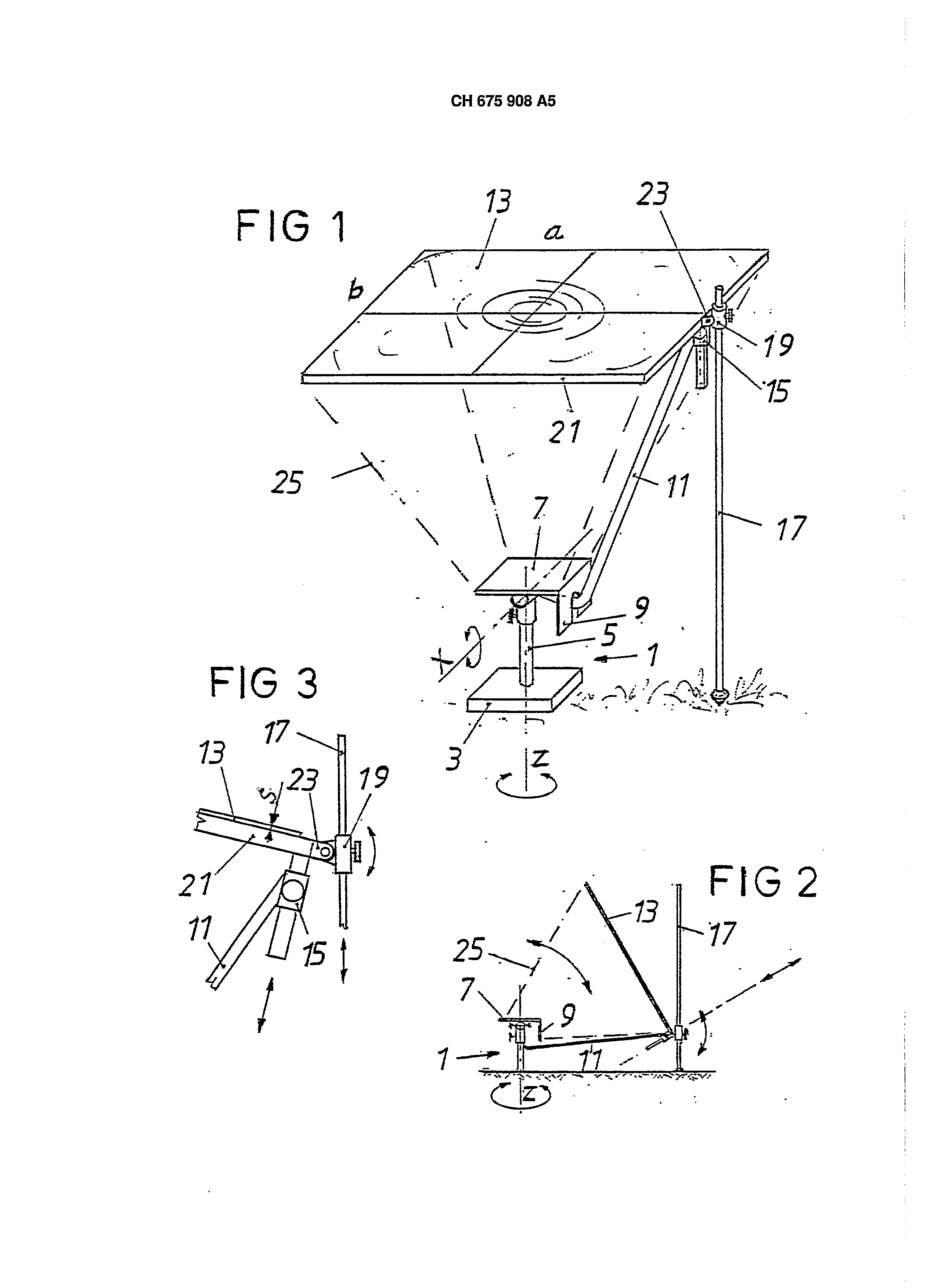
Fig. 1 equipment with essentially horizontal arranged lens in perspective representation, Fig. 2 the equipment in accordance with Fig. 1 with bent lens in side view and Fig. 3 an increased detail of Fig. 1.
On a stand 1 with a base 3 and a column 5 is swivelling (around the Z-axis), put on a Kochplatte 7 in shape of a heat accumulator plate, and an arm 11, both. As heat accumulator plate 7 is considered a plate, which at least 10% of the warmth necessary for the Kochprozess can take up and deliver during the cook procedure to the cook property. The Kochplatte 7 with its vertical thigh 9 has a large thermal capacity and a good Wärmeleitfähigkeit.
At the Kochplatte 7 the arm 11 is tiltable fastened around the x axis. At the other end of the ArlO of mes 11 a square case 15 is in some covered framework 21, in function of a lens carrier, is adjustably fastened. On the framework 21 a collecting lens is in shape of a stage collecting lens 18, also to Fresine lens mentioned and put on. The stage collecting lens exhibits the characteristic the fact that its CV factor, i.e. the relationship of its hydraulic diameter Dh to its thickness s more largely as if is, whereby s, o (v = > s, o) railways - U ist.
In the represented case are:
A A=axb and/or U =2 (a+ b).
The lens 13 can exhibit any selectable form, for example a Rechteckform.
So that the base 3 of the stand 1 does not have to be implemented too largely or too heavily, the weight of the lens becomes 13 by a support 17 getragen.
The support 17 becomes thereby in a case 19 geführt.
The Hûlse 19 is at the framework 21 between latches 23 articulated (also to the x axis of parallel drag axis) arranged. In Fig. purely schematically the lens 18 is in bent position represented 2, as it is to be adjusted with low position of the sun. The bundled sunbeams 25 fall thereby not only on the surface of the Kochplatte 7, but also on their vertical thigh 9.
So that if possible the entire energy of the jets 25 falling on the Kochplatte 7 can be absorbed, this is preferably flat black colored. In this way the Kochplatte before cooking can be warmed up, so that the cook property is warmed up not only the sunbeams 25, but at the same time also from downside by the electrical warmer 7 bundled from above by. In order to be able, Nässt the lens 13 relative to the Kochplatte 7 in the square case 15 shift to stop the illuminated surface and/or the local temperature on the electrical warmer 7 and/or a pan standing on it. The adjustment of the jets does not go on the electrical warmer 7 with each arbitrary lens position verloren.
All mobilenesses of the equipment can by means of hand screws in the desired situation blocked werden.
3 CH 675,908 A5 The solar-energy cooker comprises a plate (7) mounted on a stand (1), and a unit concentrating the sunrays into a bundle and direction them at the plate. This unit incorporates a collecting lens (13), which can be arranged to hinge in relation to the plate, its distance from the latter being also adjustable. The plate can form a heat-accumulator and there can be a vertical flange (9) on its side towards the sun. ADVANTAGE - The concentrating unit does not get dirty. 1. Equipment for cooking under utilization of the solar power, consisting of a stand (1) and a Kochplatte arranged on it (7) as well as one the Kochplatte (7) assigned device for bundling and adjustment of the sunbeams on the Kochplatte (7), by the fact characterized that the device exhibits a collecting lens (13) for bundling and adjustment of the sunbeams. 2. Equipment according to requirement 1, by the fact characterized that the collecting lens (13) tiltable with the Kochplatte (7) connected and regarding the distance to the Kochplatte is adjustable. 3. Equipment according to requirement 1 or 2, by the fact characterized that the Kochplatte (7) when heat accumulator plate is trained. 4. Equipment after one of the requirements 1 to 3, by the fact characterized that the Kochplatte (7) on the sun side a vertical thigh (9) aufweist.
Equipment after one of the requirements 1 to 4, thereby characterized that the collecting lens (13) around one parallel to the surface of the Kochplatte C7) running axle (x) is tiltable. 6. Equipment after one of the requirements 1 to 5, by the fact characterized that the collecting lens (13) by means of a framework (21) of an arm (11), which at the Kochplatte (7) is linked, is carried and that the framework (21) with a tap aehsial verschiebund ascertainable in one to the arm (11) fastened case (15) is stored. 7. Equipment after one of the requirements 1 to 6, by the fact characterized that the weight of the collecting lens (13), the framework (21) and the arm (11) partly of laterally the stand (1) arranged support (17) is carried. 8. Equipment after one of the requirements 1 to 7, by the fact characterized that the CV factor of the collecting lens (13) is larger than 8.0. 9. Equipment after one of the requirements 1 to 8, by the fact characterized that the collecting lens (13) a FresneI lens ist.
Equipment after one of the requirements 1 to 9, by the fact characterized that the Kochplatte (7) around a column (5) swivelling at the stand (1) stored ist.