Cable run at a table.
Area of application of the invention the available invention refers to a cable run at a table with cable supports as well as Stromversorgungsund/or communication sockets, those for the connection of e.g. notebooks, Beamern or Tischlampen usable sind.
State of the art the EP 1,182,747 a2 shows a plug socket unit, which is applicable into a recess of a desk top. The plug socket unit is moveable around the longitudinal axis and has a circular cross-sectional shape, which is provided with 3 flattenings against each other transferred by for instance 60°. The cable supply takes place in axial direction. Two of the flattenings serve as caps, whereby within the third flattening the socket contacts are integrated. Dependent on the turn of the plug socket unit one of the two caps covers the recess or the socket contacts is accessible for the connection of device plugs. Unfavorably with this construction the demand of the Zuführungskabel turned around by the turn of the plug socket unit as well as the management relatively difficult to operate when the rotation the closed position into the Offenstellung and. Besides the construction is relatively complex, which the device as special fitting verteuert.
From the DE 20,206,740 U1 a further plug socket unit swivelling for inserting into a recess in a desk top is well-known. This plug socket unit consists of a housing, which is seized between two to each other complementary cheeks, which are fastened to the disk lower surface. The axis of rotation runs thereby more guer for the swivelling range of the plug socket unit and sits close at an end of the housing. In the swung condition the top side of the housing formed by a cover locks within the recess concisely with the disk top side. In the swung out condition the housing with the plug socket unit rises up right-angled from the table for attaching electrical consumers. With the fact it is unfavorable that in the range, which is stressed by upward the swung out housing work surface is occupied. The construction is besides relatively complex, which raises the price of the device as installations. In addition the total optics of the table is impaired with folded up housing, which the appearance negatively beeinflusst.
Article of the DE 20,104,438 U1 is a plug socket box lockable with a cover, which essentially consists of a framework with a framework opening. The framework has a square outer section with a circulating supernatant support and, with which the plug socket box is held in a recess, e.g. within a desk top, in the assigned condition, whereby on camp and takes the edge off of the recess at the same time. Over a retaining bar the framework opening is fixed from a side. At the other side a free space remains between frameworks and framework opening. Into the framework opening a lower part is also fixable to it fastened plug socket clutches einschiebund. At the top side of the framework a cover, over linked at the inside of the framework guidance projections/leads present, is. At the narrow sides the cover possesses guide grooves, whereby in the range of a final section a circular extension is in each case. These extensions make possible that the cover can be turned by the horizontal cover position around the guide grooves into the vertical Offenstellung. By means of the guidance projections/leads the cover slides with the help of the guide grooves downward by the free space to the longitudinal fold of the cover concisely with the level of the edge of edition abschliesst.
In the DE 20 2006 016,476 U1 a plug socket unit at a workbench is revealed, which is equipped with Stromversorgungsund/or communication sockets. The plug socket unit sits in an owner, which is attached underneath the desk top. The female insert is accessible over a recess existing in the desk top, whereby from the recess of removable covers is present. The cover is also connected stored arms at the owner for tiltable and leaves themselves from a closing position, in which the cover lies within the recess, into a Offenstellung moves, in which the cover is lifted out from the recess diagonally employed. Alternatively the cover is as cover sliding over those at least a recess on the desk top top side ausgebildet.
Task of the invention in relation for the before-well-known state of the art, is the basis the invention the task to improve the cable run at a table entirely with associated cable supports as well as Stromversorgungsund/or communication sockets so that the assembly at the table is more efficiently realizable and the use of the mechanisms in the access becomes more practical. It is valid at the same time to protect to the bench-mountings aesthetic aspects. Finally those is cable run different modifications which can be created depending upon bench-mounting and equipment requirements erlauben.
Overview of the invention the cable run at a table, which exhibits a carried a desk top by an underframe, which possesses a desk top top side as work surface and a desk top lower surface, covers a plug socket block, to which electrical cables for the current supply and/or information technology are advanced and which for putting in electrical cables for current consumption and/or connection with devices of the information technology has connections. At the SteckdosenCH699314A2 Andockmittel are arranged block, which permit a solvable attaching of the plug socket block at the underframe or at a base, which neighbouring to a recess planned in the desk top arranged ist.
The Andockmittel for the plug socket block an owner for the admission of the plug socket block and fastening parts cover special first execution form of the cable run to the solvable connection of the owner with the underframe. Here the owner is provided with rest organs, which attack at complementary outlines at the plug socket block, whereby the owner and the plug socket block are solvable connected with one another. The fastening parts cover swivelling bolts for intervention at the underframe and liaison elements for the attachment of the bolts at the owner. The bolts are intended for the intervention in a prop as a component of the underframe. The prop is a hollow section with a raster of break-throughs. The bolts come internally the prop behind break-throughs too liegen.
The Andockmittel for the plug socket block connected camps and to it arranged fastening parts cover special second execution form of the cable run with this. Here that is arranged base as the recess at the desk top lower surface of bordering frameworks and the base possesses Gegenkonturen, which cooperate with the fastening parts of the camps. At the plug socket block on both sides one side piece each is arranged firmly, at whose exterior surface a further connection for putting in electrical cables for current consumption and/or - feed and/or the connection with devices of the information technology to be accessible can. The side pieces in the camps are limited swivelling geführt.
The fastening parts at a camp cover at least a freely ending tap and a Hinterschnitt planned to it. The Gegenkonturen at the base is designed as schlüssellochförmige blank dies with one extended and one each to it following narrowed range. With the Andocken of the plug socket block at the base the taps bring first into the extended ranges of the Gegenkonturen and the taps in the angedockten final state come in the narrowed ranges of the Gegenkonturen to lie, whereby edges of wall of the base intervene in the Hinterschnitte at the taps. The fastening parts at a camp and the Gegenkonturen at the base are in each case present in pairs. At the camp a locking organ is intended, for which in the base the extended range of the Gegenkontur serves as complementary organ, which are solvable with one another in the angedockten final state in interference. The locking organ at the camp is a flexibly bendable bar with a high-standing nose. At the desk top lower surface the recess circulating recess is present for using the base. An upper framework applicable of the desk top top side into the recess is intended. The recess leaves itself with an upward out-hinged cover abdecken.
Special characteristics for the first and second execution form of the Kabelführunq the prop is a square hollow section, which exhibits top side, one lower surface and two sides. The break-throughs in both sides are to each other congruently intended. The prop possesses a cavity, whereby these and the break-throughs are usable for the execution of cables. The ends of the prop are designed as Andockteile as the connection with clutch parts as a next component of the underframe. The clutch parts are at the same time usable to the cultivation of table-legs as a further component of the underframe. Hooks for hanging up into the break-throughs of the prop are intended as carriers for the cables. Furthermore adapters are intended as carriers for a channel section, in which cable can be led. The adapters come internally the prop behind the break-throughs to lie and can through tricks be locked. Finally seals are as edge of the break-throughs to the edge protection of accomplished cables vorgesehen.
Short description of the attached designs show:
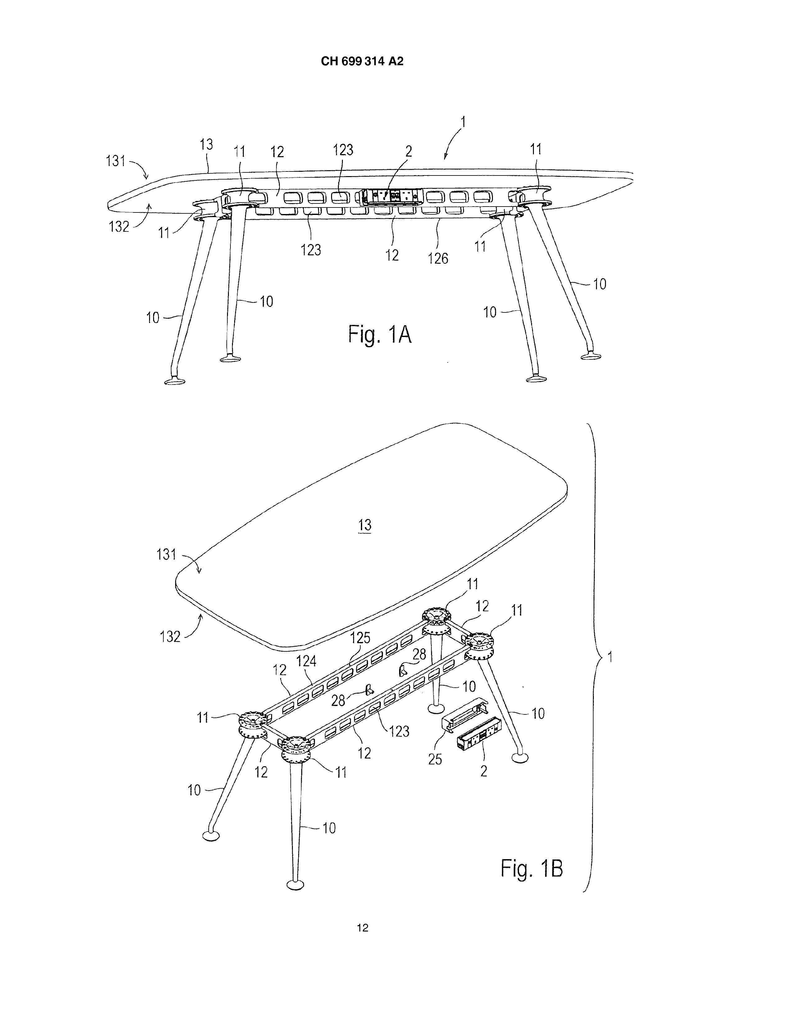
Fig. 1A a table with rechteckförmiger desk top and an underframe, consisting of clutch parts, props and table-legs, as well as a mounted plug socket block, as the first execution form of the cable run, in Perspektivansicht from downside; Fig. 1B the arrangement in accordance with Fig. 1A, with desk top taken off and solved plug socket block, in Perspektivansicht from above; Fig. 2A a prop also to it installed plug socket block and to it attached electrical cable, which run partially within the prop, in Perspektivansicht from the front; Fig. 2B the arrangement in accordance with Fig. 2A, in perspective explosive opinion; Fig. 3A an owner, in Perspektivansicht from the front; Fig. 3B the owner from Fig. 3A, in Perspektivansicht from the rear; Fig Rg Hg Fig Fig Fig Fig Fig CH699314A2 a bolt, in Perspektivansicht from the front; a part of the underframe in accordance with Fig. 1B, also at the prop used hook, a seal and adapters for the adjustment of a channel, in Perspektivansicht from the front; a prop with approximate adapters, in Perspektivansicht from the front; the arrangement in accordance with Fig. 6A, with partially used adapters, in Perspektivansicht from the front; the arrangement in accordance with Fig. 6B, with completely used adapters and approximate channel, in Perspektivansicht from the front; the channel from Fig. 6C, in increased cross section; the arrangement in accordance with Fig. 6C with partially hung up channel, in the cross section; the arrangement in accordance with Fig. 6E, with completely hung up channel, in the cross section; the arrangement from Fig. 6F, in Perspektivansicht from the front; the adapter from Fig. 6A, in increased Perspektivansicht from the front; the adapter from Fig. 6H, in Perspektivansicht from the rear; the adapter from Fig. 6H, in sectional view; the hooks from Fig. 5, in increased Perspektivansicht from the rear; the hooks from Fig. 7A, in side view; the seal from Fig. 5, in increased Perspektivansicht from the front; the seal from Fig. 8A, in sectional view; the arrangement in accordance with Fig. 2A, also at the prop fixed seals, in Perspektivansicht of of; the arrangement in accordance with Fig. 2A, also at the prop fixed seals and hooks, in Perspektivansicht from the front; a table with rectangular desk top and a recess with opened cover, as the second execution form of the cable run, in Perspektivansicht, existing therein, from the front; the table in accordance with Fig. 10A, with two recesses and covers opened in each case, in Perspektivansicht from the front; a table with round desk top and several therein existing recesses with covers opened in each case, in Perspektivansicht of of; the range of the desk top around the cutout in accordance with Fig. 10A, with the upper and lower framework, cover, attack, plug socket block, applicable therein, end caps, camps and cable basket, in perspective explosive opinion; 12The plug sockets block from Fig. 11, in increased Perspektivansicht of of; 12B the two end caps from Fig. 11, in increased Perspektivansicht from the front; 12C the both bearings from Fig. 11, in increased Perspektivansicht of of; 12D the upper framework from Fig. 11, in increased Perspektivansicht from the front; 12E - the lower frameworks from Fig. 11, in increased Perspektivansicht from the front; 12F the cover from Fig. 11, in increased Perspektivansicht from the front; 12G the cable basket from Fig. 11, in increased Perspektivansicht from the front; 13The plug sockets block in accordance with Fig. 11, with postponed end caps, in increased Perspektivansicht from the front; Fig. 4 Fig.
Fig. 6A Fig. 6B Fig. 6C Fig. 6D Fig. 6E Fig. 6F Fig. 6G Fig. 6H Fig. 6J Fig. 6K Fig. 7A Fig. 7B Fig. 8A Fig. 8B Fig. 9A Fig. 9B Fig. 10A Fig. 10B Fig. 10C Fig. 11 Fig. 13B Fig. 14A Fig. 14B Fig. 14C Fig. 14D Fig. 15A Fig. 15B Fig. 15C CH699314A2 the arrangement in accordance with Fig. 13A, with postponed camps, in Perspektivansicht from the front; the range of the desk top around the cutout in accordance with Fig. 11, with cover, fuse elements, lower framework and plug socket block with end caps as well as camps, in partial explosive opinion from downside; the arrangement in accordance with Fig. 14A, also into the recess used open cover, in Perspektivansicht from downside; the arrangement in accordance with Fig. 14B, with assigned fuse elements and assigned lower framework, in Perspektivansicht from downside; the arrangement in accordance with Fig. 14C, with completely into the lower framework used plug socket block, in Perspektivansicht from downside; the arrangement in accordance with Fig. 14D behind a prop, in the vertical cut; the arrangement in accordance with Fig. 15A before a prop in the vertical cut; the arrangement in accordance with Fig. 15B doubly mirror-symmetrically to each other in each case before a prop, in the vertical cut; and Fig. 15D the arrangement in accordance with Fig. 15A doubly mirror-symmetrically to each other in each case behind a prop, in the Vertikalschnitt.
Remark example on the basis the enclosed designs takes place below those. detailed description of a remark example for cable run according to invention at a table with the associated construction units and Baueinheiten.
For the entire further description the following definition is valid. Are in a Fig. for the purpose Bezugsziffem of graphic clarity contain, but does not describe in the directly associated description text, then to their mention in preceding descriptions of figure is referred. In the interest of the clarity the repetitive designation of construction units in following figures is mostly done without, if it is graphically clearly recognizable that it itself around “recurring” construction units handelt.
Fig. 1Aund1B the table 1 has a e.g. rechteckförmige desk top 13 with the top side 131 and the lower surface 132. The desk top 1 is carried by an underframe, which consists of four rechteckförmig arranged props 12, per a clutch part of 11 and per one arranged in each corner area at each clutch part 11 fastened table-leg 10. Those in each case both props 12, which on the associated clutch part 11 approaches, are to it befestigt.
The structure of the underframe is article of the WHERE 2008/049 244 A1 of the Anmelderin.
The props 12 have the shape of a square hollow section, which itself upright between the clutch parts of 11 extended and a raster from break-throughs has 123, which is congruently in each case in both side walls present. The prop 12 has a screw hole 125, which runs perpendicularly and withdraws at the lower surface 126 on the top side 124, so that the desk top lower surface 132 can be e.g. fastened with fixing means, to screws, on the prop 12. The break-throughs 123 are intended for the admission and locking of different components, which serve primarily the cable run and/or electrification at the table 1, like the plug socket block 2 applicable into an owner 25 and the owner fixing bolts 28, in addition, secondary parts to the cable run in accordance with later description. The components for electrification can heretofore be installed at the props 12 putting on the desk top 13, whereby the entire assembly simplifies wird.
Fig. 2A to 4 the prop 12 has 120 for connection with the clutch part 11 at its opposite ends in each case a Andockteil. Internally a cavity 122, which is usable for the execution of electrical cables 9, is appropriate for the prop 12. At the prop 12 the quaderförmige owner 25 fixable by means of bolts 28 is. The owner 25 has an admission 26, into the soft plug socket block 2 is applicable. The admission 26 changes into a break-through, which depresses to from electrical connections and cables is usable. Neighbouring for the admission 26 one throughhole each 250 is present at the owner 25, which depresses the spigot 281 of the bolt 28 serves, whereby the spigot goes off 281 a bar 280 right-angled. By means of screw 29 the bolt 28 is swivelling in the throughhole 250 of the owner 25 positioned. From the corner areas of the owner 25 extends in each case a rest organ 251, which is provided with a clip-like shaping at its free end, whereby in each case two rest organs 251 face each other and their shapings against each other shows. In opposite direction of the rest organs 251 one attack each 252, that rises the form of a tap hat. beside the throughholes 250
CH699314A2 with owner 25 installed at the prop 12 lie the bars 280 the bolt 28 in the cavity 122 of the prop 12 and extend in longitudinal direction of the owner 25 and/or the prop 12. By manual rotating of a bar 280 into the transverse direction, which is preferably done via the break-through 123 facing in addition, i.e. until the bar 28 runs transverse to the longitudinal extending of the owner 25 and/or the prop 12 and comes with one flank each because of the attacks 252 to be, the owner 25 with the prop 12 is blocked. The clamping effect is obtained by the fact that the bars 280 with their surfaces of the cavity 122 of the prop 12, arranged to the spigot 281, rest against their inner wall, whereby the appropriate Klemmkraft is adjustable over the screws 29. At the owner 25 a paragraph 27 is present, which comes to lie with its circulating edge in the appropriate break-through 123 of the prop 12, which serves as positioning assistance and additional locking. The plug socket block 2 is engaged in defined adjustment of the connections into the owner 25. The rest organs reach 251 into complementary outlines at the plug socket block 2. the connections 20 are for attaching cables 9 to the current supply or data communication bestimmt.
Fig. 5, 9A and 9B at the prop 12 can further construction units be attached, i.e. first hook 3 for the suspension of cables 9 and seals 34 than edge protection for the execution of cables 9 by the break-throughs 123 into the cavity 122 inside or from this. At the prop 12 furthermore adapters 35 can those be attached, to the Andocken of a channel 38 for the guidance of cables 9 or collection of excess lengths of cables 9 dienen.
So far treated first execution form cable run facilitates entire electrification to table 1 thereby that one at the established underframe - this builds oneself up at least from a prop 12 and table-legs - which electricity installation can insert with standing underframe completely without underneath the desk top 13, i.e. under the table 1, works to have. The wiring takes place quasi from above. Only after completion of the electricity installation the desk top 13 is installed on the underframe. The expiration of assembly is particularly favourable with large tables 1, which are intended for conference purposes e.g. and are practically impracticable at those from there the reversal of such heavy, wide tables 1 with the table-legs 10 upward - for the relieved accesibility of the underframe -. Such tables 1 have usually several desk tops 13 which can be joined, which are installed after the wiring. By the use of the special prop 12 it is very simple to attach to it plug socket blocks 2 from both sides so that plug socket blocks 2 turned by each other opposite jobs access exists in each case to. Besides the props consisting of hollow section are 12 with the systematic break-throughs 123 to the transmission of cables 9 and the more einoder reciprocal Andocken of cable 9 basic hooks 3 and channels 38 nutzbar.
Fig. 6A to 6K the adapter 35 is square in its surface area 359 and has in the center an opening 355. At the side, which is turned to the prop 12 in the installed condition, the adapter exhibits 35 a bolting device part of 350 in form of a circulating collar, whereby an upper groove 353 and a lower groove 354 develop. Following the slots 353.354 the surface area 359 is present. The upper groove 353 and the lower groove 354 possess a larger radius at a side of the collar, like at the opposite side. Neighbouring to the upper groove 353, quasi the prop 12 turned away, a further groove 356 runs, at whose top side a first fixed bracket 351 sits. Opposite the first fixed bracket 351 a second fixed bracket 352 is intended, whereby the second fixed bracket 352 over the first fixed bracket 351 out-stands and the wedge outlines arranged at the two fixed brackets 351.352 one on the other adjusted sind.
Between the two fixed brackets 351.352 a recess 357 is present, in that itself the opening 355 befindet.
When the assembling of the adapter 35 at the prop 12 the adapter 35 the break-through 123 is first approximate, the two fixed brackets 351.352 are positioned parallel to both narrow sides of the break-through 123. The adapter 35 in this position into the break-through 123 brought in to the bolting device part 350 with its surface area 359 at the prop 12 fastens. Subsequently, the adapter 35 is turned against the clockwise direction around 90°, which is made possible by the larger radius in each case a side of the collar. A direction of rotation in the clockwise direction is not possible due to the smaller radii, which face the larger radii. In end position of the adapter 35 are the two slots 353.354 in interference with the two longitudinal wall edges of the selected break-through 123. Thus the adapter 35 fixed at the prop 12 is. The first fixed brackets 351 lie parallel, beabstandet to the top side 124, whereas the second fixed brackets 352 parallel beabstandet to the lower surface 126 verlaufen.
The channel 38 has the form of an oblong channel with a ground 385, from which on both sides one rising thigh each 384 continues. At their free ends curved thighs 384 leave an upward open entrance 383 to each other. At the back thigh 384 a first outline 381 is arranged in form of a auskragenden nose. At the ground 385 a second outline 382 is in shape of a Vertiefung.
With the channel 38 into the adapters 35 inserted first the first outline 381 of the channel 38 into the groove 356 of the adapter 35 is brought in, whereby the first fixed bracket 351 of the adapter 35 with its wedge outline behind-seizes the first outline 381 of the channel 38 not yet completely. The ground 385 of the channel 38 rests upon partially the second fixed bracket 352. With the further the channel 38 downward curved to the wedge outline of the first fixed bracket 351 from the adapter 35, which behind-seizes outline 381 of the channel 38 completely, inserted the second fixed bracket 352. At the same time the wedge outline comes because of the second fixed bracket 352 within the second outline 382 at the channel 38 to be. In end position CH699314A2 is the channel 38 due to its first and second outlines 381.382, which are in interference with the wedge outlines of the first and second fixed brackets 351.352 of the adapter 35, against unintentional release gesichert.
Fig. 7A to 8B the hook 3 has in principle the form of a channel with a ground 30, from which back a vertically ascending bar 31 and front-laterally a thigh 32 curved upward continue. At the extension of the ground 30, over the bar 31 outside, are a lower snap-in configuration 300 as well as at the end a wedge outline 301. At the upper end of the bar t-shaped a transverse bar 33 sets 31, at which an upper snap-in configuration 300 as well as at the end likewise are a wedge outline 301. The hook 3 has an opening 330 flowing upward, which is restricted by free ends of the thigh 32 and the transverse bar 33. The extension of the ground 30 and the transverse bar 33 are arranged flexible, so that the hook 3 into the break-through 123 can be slid, and in the assigned condition of the hook 3 the lower and upper snap-in configurations 300 in interference with the two longitudinal wall edges of the selected break-through 123 of the prop 12 are. The wedge outlines 301 make an easier pushing of the hook in for 3 possible into the selected break-through 123 at the prop 12.
The seal 34 consists of flexible material and possesses the form of a rechteckförmigen ring with a centric recess 340. Outwardly the seal 34 has a circulating groove 341, whereby the seal 34 inserted into a break-through 123 at the prop 12 remains in position. Cuts 342 make an easier halving for the seal possible 34, if this is to be used 20 into a quasi only half existing break-through 123 at the beginning or end of the prop and one from there only half of the seal 34 benötigt.
Fig. 10Abis10C in a first table configuration (Fig. 10A) is intended in the rectangular desk top 13 of the table 1 only one recess 133, which can be locked with a hinged cover 58. Momentarily the high-standing cover 58 is in the Offenstellung. By the recess 133 one arrives at here the not visible electricity installation, in particular at the connections 20 of a plug socket block 2 and the associated and/or cables 9. which can be connected
In a second table configuration (Fig. 10B) are intended in the rectangular desk top 13 of the table 1, which offers two opposite jobs, two to each other neighbouring recesses 133, which can be locked in each case with a hinged cover 58. Each user arrives also here arranged by its job by the associated in each case recess 133 at the electricity installation, underneath the one cable basket 8 ist.
The cable basket 8 serves to accomodate to 9 cables or excess lengths davon.
In a third table configuration (Fig. 10C) with e.g. five jobs has the desk top 13 of the table 1, which is e.g. approximately or oval, according to five recesses 133, which are lockable in each case with a hinged cover 58. Each user has cable basket 8 arranged by its job by the associated in each case recess 133 entrance to the electricity installation, below that in ist.
Fig. the represented cutout of the desk top 13 the recess 133 has 11, in which a groove is present 134. An upper framework 5 furthermore intended with associated attack 57 einsetzbarerer of the desk top top side 131 into the recess 133 as well as a cover 58 are. For the assembly of the desk top lower surface 132 a lower framework 4 is certain, to which - assembled - the plug socket block 2 as well as ever two the end caps 6 and camp 7 can be andocken. Finally a cable basket 8 belongs to the total structure. One plans the upper framework 5 only if the surfaces of the recess are uncoated 133 and are for optical reasons from there to be taken off; this contrary to the Fig. 14A-14D.
Fig. 12Abis12C the plug socket block 2 is of rechteckförmiger shape and possesses several connections 20, those depending upon country-specific standard or employment-dependent equipment varies and e.g. next to each other at a long side and/or oppositely at the narrow sides attached its können.
The two end caps 6 are provided with in each case an enclosure 62. Following the enclosure 62 a flange 61 is intended, from which a cylinder section 60 continues, which ends with an exterior surface 63. Between exterior surface 63 and cylinder section 60 a losing protection 64, and in the transient area from the cylinder section to the flange 61, an attack 65 is present. In the exterior surface 63 there are screw holes 66.
From the bearing ring 70 a first strut 72 and a second strut 73 extend in radial direction, between which a covering vine 71 runs. On the covering vine 71 close of the first and second strut 72.73 in each case a tap 74 present with a Hinterschnitt 76 is. The bearing ring 70 has a recess 75 at the inside. In the corner area between the covering vine 71 and the first strut 72 from the camp in each case an axle 77 extends 7 in axial direction to the bearing ring 70. The two axles 77 at the camps 7 run in opposite directions. From the first strut 72 close sets a fixed bracket for the first covering vine 71 78, whereby the second strut 73, close of the covering vine 71 a hook 79 goes off, that for cable run dient.
Fig. 12D CH699314A2 the upper framework 5 is likewise of rechteckförmiger shape and has the passage 56 as well as a circulating edge 50, from which a collar 51 continues. Along the long sides of the collar 51 rest noses 52 are present, which are intended for the complementary, later interference with the snap-in configurations 41 at the lower framework 4. In the transverse sides of the collar 51, near the corner areas to a long side, in each case a recess 53 lies. The transverse sides possess a bending 54 with an admission existing therein 55, in the attack 57 serving for the mounting plate of the cover 58 applicable ist.
Fig. 12E the lower framework 4 is of rechteckförmiger shape and has the passage 46. Two to each other parallel longitudinal thighs 40 are present, between which two parallel transverse thighs 42 extend. Along the two longitudinal thighs 40 snap-in configurations 41 are present. Parallel beabstandet to the transverse thighs 42 there are in each case two one behind the other lying schlüssellochförmige blank dies 43, between which an attack 48 sits. Neighbouring to in each case a blank die 43 actual just as parallel beabstandet to the transverse thighs 42 - an oblong guide groove 44 available. Between guide groove 44 and passage 46 is an admission 45, into which the attack is insertable 57. Screw nests 47 lie in the corner areas between the longitudinal thighs 40 and the transverse thighs 42. A bar 49 rises in each case between the snap-in configuration 41 and the blank die 43 and towers above thereby the attack 48.
Fig. 12F the rechteckförmige cover 58 serves the recess 133 in the desk top 13 for locking. At the narrow sides of the cover 58 in each case to each other fluchtendes an oh hole 59 is present, that the adjustment of the cover 58 by means of a fuse element 139 serves (S. Fig. 14A).
Fig. 12G the cable basket 8 has a rectangular ground of 80, from which two parallel beabstandete cams 81 and a circulating edge rise, from which two facing handles 82 goes off. In the handles 82 one oh hole each 89, those lies to each other fluchten.
Fig. 13Aund13B this pair of figures illustrates a building of the plug socket block 2 with two the end caps each 6 and camps up 7.
Fig. 13A: 1. Assembly step first is pushed per an end cap 6 completely onto each of the two narrow sides of the plug socket block 2, so that the flange 61 concisely against the plug socket block 2 rests. The enclosure 62 of the end cap 6 intervenes in complementary outlines at the appropriate narrow side of the plug socket block 2. By in the exterior surface 63 of the end cap of 6 existing screw holes 66 the end cap is on fixed to 6 2 screwing channels existing by means of fastening parts at the plug socket block. At the narrow sides of the plug socket block of 2 arranged connections through-rise up axially the cylinder section 60 and form quasi a concise conclusion with the exterior surface 63 for the end cap 6.
Fig. 13B:. 2. Assembly step on each end cap 6 is postponed a camp 7. The camps 7 enclose then with their bearing ring 70 axially in each case the cylinder sections 60 of the end caps 6. in the recess 75 of the bearing ring 70, running in addition, come the attack 65 of the end cap 6 to lie, so that rotating of the plug socket block 2 with the associated end caps 6 within the camps which are certain later 7 on e.g. 65° is limited. The losing protection 64 embraces partially the respective bearing ring 70 and prevents thereby an unintentional loosening of the camps 7 from the end caps 6.
Fig. 14Abis14D this figure sequence shows the gradual installation of the cover 58 and the lower framework 4 into the recess 133 of the desk top 13 as well as the Andocken of the construction unit from plug socket block 2, end caps 6 and camps 7 at the lower framework inserted before 4th to the upper framework 57 can one do without here, there the edges of the recess 133 with the surface of the desk top 13 a coating - e.g. a powder coating - exhibit, so that also quasi seals the surfaces in the recess 133 sind.
Fig. 14A: 1. Assembly step in the starting situation is vacant the recess 133, the cover 58, the lower framework 4 and the plug socket block 2 with installed end caps 6 and camps 7 is made available for the assembly. At the desk top lower surface 132 the recess 133 of a windshield frame section-like recess 135 is bordered, in the holes 136 for the admission of fastening parts intended sind.
Fig. 14B: .2. First we that cover 58 inserted assembly step from the desk top top side 131 into the recess 133, whereby the oh holes are brought to 59 of the cover 58 with the respective groove 134 in the recess 133 in escape. The lower RahCH699314A2 men 4 by the desk top lower surface 132 of the recess 133 is approximated. The construction unit from plug socket block 2, end caps 6 and camps 7 lies further in Bereitstellung.
Fig. 14C: 3. Assembly step the lower framework 4 is used by the desk top lower surface 132 into the recess 135 and is fixed by means of by the screw nests of 47 4 fastening parts thorough at the lower framework in the holes 136. In each case a bar 49 of the lower framework 4 into the neighbouring groove 134 rises up. With the fuse element 139, which through-rises up the oh hole 59 in the cover 58 and is in the bar 49, the cover 58 is fixed. The construction unit from plug socket block 2, end caps 6 and camps 7 is approximated the lower framework 4 by the desk top lower surface 132, whereby one the taps 74 of the camps 7 on the blank dies 43 ausrichtet.
Fig. 14D: 4. Assembly step finally is angedockt the construction unit made of plug socket block 2, end caps 6 and camps 7 at the lower frameworks 4. The fixed brackets 78 are inserted with their freely rising ends into the guide grooves 44 and to rise up the taps 74 into the extended ranges of the blank dies 43, so that the wall of the lower framework 4 comes to be on the level of the Hinterschnitte 76 the tap 74. From this the construction unit with the plug socket block 2 shifted, whereby the fixed brackets 78 first from the guide grooves 44 are pressed, the taps 74 into the narrowed ranges of the blank dies 43 to bring in and the narrowed ranges of the blank dies of 43 surrounding edges of wall of the lower framework 4 between the covering vine 71 and the Hinterschnitte 76 arrive. With reaching the end position the springy fixed brackets 78 jump into the respective extended range of the neighbouring blank die 43 and lift themselves with their freely rising ends against the outside edge concern there blank die 43. Thus is the construction unit from plug socket block 2, end caps 6 and camps 7, angedockte at the lower frameworks 4, arretiert.
At the lower surface the bearing ring 70 of the camp 7 has a parting 700, that for the limitation of the swivelling range of the cable basket 8 dient.
If one wants to solve the construction unit from plug socket block 2, end caps 6 and camps 7 from the lower framework 4 from the angedockten position, the fixed brackets 78 are so far bent downward, until of them arrive freely rising ends from the extended ranges of the blank dies 43 and the locking of the angedockten construction unit with the plug socket block 2 is waived thereby. Now the construction unit can be moved against the module direction, until the taps 74 at the attacks 48 at the lower framework 4 impacts. Now the taps 74 stand in the extended ranges of the blank dies 43, so that one can solve the complete construction unit with the plug socket block 2 of the lower framework 4. The attacks 48 prevent that the taps 74 are too far pushed beyond the release position and with their Hinterschnitten 76 at the lower framework 4 verklemmen.
Fig. 15Abis15D in this figure sequence are represented at a desk top 13 individual or recesses in pairs of 133 as well as assigned construction units and construction units in varying arrangement to the props 12, which component the desk top of 1 basic underframe are. A lower framework 4, a momentarily lifted up cover 58 and a construction unit from plug socket block 2, end caps 6 and camps 7 are present always. By the examples is assumed one uses an upper framework 5 in each case. The upper framework 5 lines the recess 133, covers their circulating edge, to which at the desk top top side 131 flows and places thus an optically perfect conclusion her.
After inserting the lower framework 4 into the recess 133 (Fig. 14A to 14D) is introduced the upper framework by the desk top top side 131 into the recess 133. Here the rest noses 52 of the upper framework 5 catch into the snap-in configurations 41 of the lower framework 4, whereby the upper framework 5 is fixed. The attack 57 is put by the admission 55 in the upper framework 5 and reaches through in addition escape-ends to admission 45 in the lower framework 4. one begins per cover 58 one or more attacks 57 to the noise suppression with intended or inadvertent closing of the cover 58. If the upper framework 5 is renounceable, the attack becomes 57 only in the admission in the lower framework fixiert.
The suspension of the cable basket 8 is identical with all variants. The free tapered ends of the axles 77 of the two camps 7 sitting on the end caps 6 through-rise up themselves the oh holes 89 in both from the tray-like ground 80 of the cable basket 8 raising handles 82, so that the cable basket 8 between the axles 77 is tiltable hung up. Of the ground 80 of the cable basket 8 rising cams 81 intervene in the partings 700 at the lower surface of the bearing rings 70 that-being certain camps 7, so that an additional lateral guidance and at the same time a delimitation of the swivelling range for the cable basket 8 in an educated manner werden.
Fig. 15A: I.Variante for the cable run at the table 1 with e.g. only one job are behind a prop 12 individual recess 133 in the desk top 13 with the associated construction units and the construction unit from plug socket block 2, end caps 6 and camps 7 vorgesehen.
F: .2. Here variant CH699314A2 are for the cable run at the table 1 before a prop 12 individual recess 133 in the desk top 13 with the associated construction units and the construction unit from plug socket block 2, end caps 6 and camps 7 angeordnet.
Fig. 15C: 3. Variant for the cable run at a table 1 with e.g. two jobs each other in pairs opposite recesses 133 in the desk top 13 intended, i.e. mirror-symmetric to a prop running between them 12 are. Each recess 133 is with the associated in each case construction units and a construction unit from plug socket block 2, end caps 6 and camps 7 bestückt.
Fig. 15D: 4. Here variant opposite recesses 133 in the desk top 13 are each other in pairs intended, i.e. between two to each other parallel beabstandeten props 12 for the cable run at the table 1 with again e.g. two jobs. Each recess 133 is with the associated in each case construction units and a construction unit from plug socket block 2, end caps 6 and camps 7 bestückt.
Equally also the second execution form of the cable run facilitates the entire electrification at the table 1 by the fact that one can install the electricity installation at the standing underframe completely. The wiring takes place again with desk tops 13 not put on yet quasi from above. Only after completion of the electricity installation the desk top 13 or a multiplicity of it is installed with the bases 4 attached before on the underframe. Afterwards it requires only more the Andockens of the construction units from plug socket blocks 2, end caps 6 and camps 7 at the bases 4, which e.g. as lower frameworks 4 is designed. By the recesses to 133 in the desk top, take offable with a cover 58, 13 each user arrives at one limits swivelling plug socket block 2. is usable the props 12 with the raster of break-throughs 123 at the transmission of cables 9 and the more einoder reciprocal Andocken of cable 9 basic hooks 3 and channels 38, also consisting of hollow section, here. Thus one is creative montageund user friendly cable run at the table 1 considering aesthetic aspects. The cable run at a table (1), which one of an underframe (10, 11, 12) exhibits carried desk top (13), which possesses a desk top top side (131) as work surface and a desk top lower surface (132), covers a plug socket block (2), at the electrical cables (9) for the current supply and/or information technology are advanced and the connections (20) for putting in electrical cables (9) for current consumption and/or connection with devices of the information technology has. At the plug socket block (2) are Andockmittel (25, 28, 29; 7, 74) arranged, the one solvable attaching of the plug socket block (2) at the underframe (10, 11, 12) or at a base (4) permits, which neighbouring to one in the desk top (13) intended recess (133) is arranged. With a first execution form of the cable run the Andockmittel (25, 28, 29) for the plug socket block (2) an owner (25) covers for the admission of the plug socket block (2) and fastening parts (28, 29) to the solvable connection of the owner (25) with the underframe (10, 11, 12). Here the owner (25) is provided with rest organs (251), which at complementary outlines at the plug socket block attack (2), whereby the owner (25) and the plug socket block (2) is solvable connected. With a second execution form of the cable run covers the Andockmittel (7, 74) for the plug socket block (2) with this connected camps (7) and to it arranged fastening parts (74, 76). Here that is base (4) as the recess (133) at the desk top lower surface (132) bordering framework (4) arranged, and the base (4) Gegenkonturen (43) possesses, those with the fastening parts (74, 76) of the camps cooperate (7). 1. Cable run at a table (1) with:
a) one of an underframe (10,11,12) carried desk top (13), which exhibits a desk top top side (131) as work surface and a desk top lower surface (132); b) a plug socket block (2), at the electrical cables (9) for the current supply and/or information technology is advanced and the connections (20) for putting in electrical cables (9) for current consumption and/or connection with devices of the information technology it possesses, by the fact characterized that c) at the plug socket block (2) Andockmittel (25, 28,29; 7,74) is arranged, which a solvable attaching of the plug socket block (2) at the underframe (10,11,12) or at a base (4) permits, which neighbouring to one in the desk top (13) intended recess (133) is arranged. 2. Cable run according to requirement 1, by the fact characterized that a) the Andockmittel (25,28,29) for the plug socket block (2) an owner (25) for the admission of the plug socket block cover (2) and fastening parts (28,29) for the solvable connection of the owner (25) with the underframe (10,11,12); and b) of the owners (25) with rest organs (251) is provided, which at complementary outlines at the plug socket block attack (2), whereby the owner (25) and the plug socket block (2) is solvable connected. 3. Cable run according to requirement 1, by the fact characterized that a) the Andockmittel (7,74) for the plug socket block (2) with this connected camps cover (7) and to it arranged fastening parts (74,76); b) the base (4) as the recess (133) at the desk top lower surface (132) bordering framework (4) is arranged; and c) the base (4) Gegenkonturen (43) possesses, which with the fastening parts (74,76) of the camps cooperate (7). 4. Cable run after at least one of the requirements 1 and 2, by the fact characterized that the fastening parts (of 28,29) swivelling bolts (28) to the intervention at the underframe (10, 11, 12) and liaison elements (29) for the attachment of the bolts (28) at the owner (25) umfassen.
Cable run after at least one of the requirements 1, 2 and 4, by the fact characterized that the bolts (28) are intended a) for the intervention in a prop (12) as a component of the underframe (10,11,12); b) the prop (12) a hollow section with a raster of break-throughs (123) is; and c) the bolts (28) internally the prop (12) behind break-throughs (123) to lie come. 6. Cable run after at least one of the requirements 1 to 5, by the fact characterized that a) the prop (12) a square hollow section is, which exhibits top side (124), one lower surface and two sides; b) the break-throughs (123) in both sides to each other are congruently intended; and CH699314A2 e) the prop (12) a cavity (122) possesses, whereby these and the break-throughs (123) for the execution of cables (9) is usable. 7. Cable run after at least one of the requirements 1 to 6, by the fact characterized that a) the ends of the prop (12) are designed as Andockteile (120) as the connection with clutch parts (11) as a next component of the underframe; and b) the clutch parts (11) at the same time to the cultivation of table-legs (10) when a further component of the underframe are usable. 8. Cable run after at least one of the requirements 1 to 7, by the fact characterized that a) hook (3) for hanging up into the break-throughs (123) of the prop (12) as carriers for the cables (9) is intended; b) Adapters (35) as carriers for a channel section (38) are intended, in which itself cable (9) to lead leave; c) leave themselves the adapters (35) internally for the prop (12) behind the break-throughs (123) to be appropriate come and through to tricks lock; and d) seals (34) as edge of the break-throughs (123) to the edge protection of accomplished cables (9) are intended. 9. Cable run after at least one of the requirements 1, 3 and 6 to 8, by the fact characterized that a) at the plug socket block (2) on both sides ever a side piece (of 6) is firmly arranged, at whose exterior surface a further connection (20) to putting in electrical cables (9) for current consumption and/or - feed and/or the connection with devices of the information technology to be accessible can; and b) the side pieces (6) in the camps (7) limited swivelling led sind.
Cable run after at least one of the requirements 1, 3 and 6 to 9, by the fact characterized that a) the fastening parts (74,76) at a camp cover (7) at least a freely ending tap (74) and a planned a Hinterschnitt (76), to it; b) the Gegenkonturen (43) at the base (4) as schlüssellochförmige blank dies (43) with ever an extended and a one to it following narrowed range are trained; and c) with the Andocken of the plug socket block (2) at the base (4) the taps (74) first into the extended ranges of the Gegenkonturen (43) bring and the taps in (74) in the angedockten final state in the narrowed ranges of the Gegenkonturen (43) to lie come, whereby edges of wall of the base intervene (4) in the Hinterschnitte (76) at the tap (74). 11. Cable run after at least one of the requirements 1, 3 and 6 to 10, by the fact characterized that a) the fastening parts (74, 76) at a camp (7) and the Gegenkonturen (43) at the base (4) in pairs is in each case present; and b) at the camp (7) a locking organ (78) is intended, to which in the base (4) the extended range of the Gegenkontur (43) as complementary organ serves, which are solvable with one another in the angedockten final state in interference. 12. Cable run after at least one of the requirements 1.3 and 6 to 11, by the fact characterized that the locking organ (78) at the camp (7) a flexibly bendable bar with a high-standing nose is. 13. Cable run after at least one of the requirements 1, 3 and 6 to 12, by the fact characterized that a) at the desk top lower surface (132) the recess (133) circulating recess (135) for using the base (4) is present; b) an upper framework applicable of the desk top top side (131) into the recess (133) (5) is intended; and c) the recess (133) with an upward out-hinged cover (58) to cover leaves itself.