Pivot for clockwork movement.
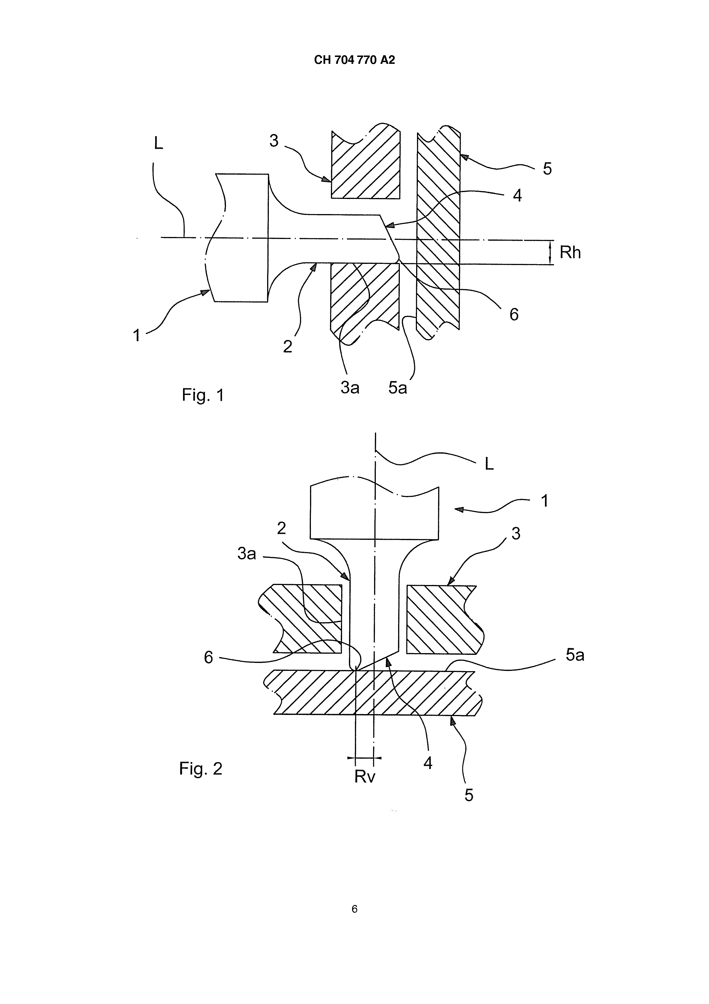
HM 704,770 a2 specification technical field la invention generally relates to the technical field of watchmaking and more particularly the field of clock movements mounted in watches. these normally include various mechanisms and/or the gear trains whose operation may be influenced by their orientation with respect to gravity. Indeed, there is often performance differences and/or performance of these mechanisms and/or the gear trains, [...] ' they pass from a substantially horizontal orientation to a substantially vertical orientation and vice versa. a example, [...] ' a timepiece movement extends substantially vertically, the axis on which it is mounted generally extends substantially horizontally. When the movement is oriented substantially horizontally, it is the axis which, in general, is oriented substantially vertically. As a result of these different orientations, mechanical effects that can induce a difference in path length for the movement. l'influence of the orientation with respect to gravity is manifested particularly at the friction between pivots and bearings and between pivots and stones stone. il referred more particularly to pivot pins used to perform a balance staff or assigned to a wheel of an escapement mechanism, but the invention is not limited to these applications. State of technology on already known pivots to specific geometries, especially the cylindrical pivot, the pivot free tapered bearing surface, the pivot ended tapered rubs at the bottom of a step bearing, which are described in the dictionary professional illustrated the timepiece fooled, flat end to the pivot and the pivot diameter conical, which are described in the communication no. 4 of the 46th congress company Swiss timer "measurements of the brittleness of the rocker pins having axes" of Schlatter Disease and Lehmann. a example, it is known, for example by means of the work "theory of clockwork", on page 155, edited by the federation to schools technical (isbn 2-940025-10 - the X, October 1998), that the amplitude of a spring balance of a watch is influenced by the variation of friction on ISI pivot of the rocker. Thus, when the watch is horizontal, the axis of the rocker arm presses vertically by the end of a pivot on an endstone. when the watch is vertical, the balance axle supported by its two pivots in two holes in stone or in bearings. The friction is thus more important when the watch is in the vertical position. to compensate for this variation of friction, it has been devised to realize pivots to flat ends rather than rounded to increase the radius of action of the frictional force when the watch is horizontal and, therefore, decrease the difference in friction between the horizontal and vertical positions of the watch. The fulcra flat have however the disadvantage that the camming action of the frictional force may vary from one element to the other, due to, for example, conditions of surfaces of the parts in contact or dust or particles that may be present in lubricating oils. The moments of friction forces can then vary from one movement to another or over time for a same motion. de similarly, these problems are encountered also with cylindrical pivots known, which has a bearing surface in contact with the stone wall surrounding a hole. le conical pin without scope is in contact with the endstone in a point centered on its axis of rotation when the watch is horizontal. Thus, the moment of friction exerted by the endstone is theoretically zero and low in practice. But when the watch is vertical, the lever arm involved in calculating moments of forces exerted by the bearings on the two pivots is equal to the radius of the pivot. The moment of friction force is larger. In passing from a horizontal to a vertical position, or vice versa, the difference between the moments of the frictional forces exerted on the pivots is maximum. In the case of a resonator which is unbalanced isochronism (in this specific case, a variation in dependence on the amplitude), running stability of such a clockwork movement is thereby affected. Disclosure of the invention l'object of the present invention seeks to provide a novel pivot clockworks for purposes beyond above drawbacks and for decreasing the difference in path length of movement, between its horizontal and vertical positions with respect to gravity. un another object of the present invention aims at providing a novel pivot for of clockworks, whose manufacture is simple and economical. the objects assigned to the invention are achieved by means of a pivot for a watch movement, to be engaged in a guide means and whose free end is able to bear on a bearing surface, characterized in that the free end has a configuration in which the portion for bearing against the bearing face 704,770 a2 HM is a contact end is radially offset from its longitudinal pivot axis, towards the periphery of said pivot. on then obtains an axial region free from contact. The area in which there is contact between the pivot and the bearing face is offset from the pivot axis of said pivot and substantially exactly located. le guide means is for example a bearing and bearing surface is for example one face of an endstone. l ' contact end preferably includes at least one vertex to establish point-type contact with the endstone. according to one exemplary preferred embodiment of the pivot according to the invention, the free end of said pivot has a wedge shape for conforming the contact end. in another example of a preferred embodiment according to the invention, the pivot has at its free end a bore extending along the longitudinal axis, so as to delimit the contact end as a shroud peripheral contact. le term "bore" is to be included in the present invention in a very broad sense, namely that it also indicates a flat-bottomed hole. la peripheral contact ring advantageously has an internal chamfer for offsetting more the parts contacting the radial periphery of said pivot. according to an exemplary preferred embodiment, the pivot according to the invention is made of a metal material. the objects assigned to the invention are also achieved by a timepiece including a pivoting axis with at least one pivot according to the invention. la timepiece constitutes for example a balance or a wheel of a clock mechanism, for example an escape wheel. the objects assigned to the invention are also achieved by means of a watch movement comprising at least one pivot according to the invention. un remarkable advantage of the pivot according to the invention is that it results in a substantial decrease in the distance between the points values of frictional forces on the pivot, respectively in horizontal and vertical position. The pivot according to the invention provides a measure of the typical deviation "flat-hanging" move to about 10 degrees, while the same measurement for said movement comprises a pivot having a rounded tip, can reach about 50°. A measurement of difference "flat-hanging" measure is the difference between the magnitude of a movement in the horizontal position and the same motion in vertical position. un the pivot further advantage of the invention lies in its insensitivity to dust or particles that may be contained in the lubrication oil. This dust and particles are not able to be introduced between the pivot and the bearing face of said pivot for moving randomly the contact area, as is the case with flat pins. The pivot according to the invention thus provides a very stable position of the contact area. le pivot claimed in the invention has the further advantage of relieving the operation difference resulting from deviation magnitudes between the horizontal and vertical positions if [...] is not perfectly isochronous. Brief description of the drawings d'other features of the present invention will appear more clearly upon reading the description which will follow, made with reference to the attached drawing, exemplary illustrative and not limiting, in which: figure 1 -, - represents the fig.. 2, represents vertical, the fig. -. 3, represents the fig. -. 4, - and the fig.. 5, an exemplary embodiment of a pivot according to the invention, in a horizontal position, an exemplary embodiment of a pivot according to the invention of fig. 1, in a position another example embodiment of a pivot according to the invention, according to a front view, represents another exemplary embodiment of a pivot according to the invention of the fig.. 3, when viewed from the left, represents yet another example embodiment of a pivot according to the invention, as a sectional view. (E) one embodiment of the invention the elements structurally and functionally identical and on multiple distinct patterns, are assigned the same reference numeric or alphanumeric. Figure 1 shows a 704,770 a2 la ch-pivot pin 1 according to the invention in a horizontal orientation, corresponding for example to a motion or to a pump oriented vertically. Its longitudinal axis L then extends horizontally. A cylindrical end portion 2 of the pivot 1 is engaged in a bearing 3 and relies specifically on an inner face of said bearing 3a 3, by establishing a contact line. This bearing 3 can also be replaced by any type of guide means. le pin 1 has at its free end, an end face 4 opposite a bearing face, for example a face 5a an endstone 5. in some applications, the endstone 5 could be replaced by a bearing complementary or any other element having an abutting face. l ' free end of the pin 1 has, with its end face 4, taper-shaped with an apex 6. the latter is radially offset with respect to the longitudinal axis L, towards the periphery of the pivot 1. the parts making contact between the pivot 1 and the endstone 5 are therefore off-axis. la wedge shape and therefore the top 6 are obtained for example by machining or rolling. The top 6 is located preferably at closer to the periphery of the end portion 2. a bulk polishing is preferably performed after the rolling. la line contact between the end portion and the inner face 2 3a extends at a first radial distance Rh of the longitudinal axis L. this first radial distance Rh which corresponds to the radius of the end portion 2. la Figure 2 shows the pivot 1 according to the invention in a vertical orientation. Its longitudinal axis L thus extends vertically. The end portion 2 of the pivot 1 is still engaged in the bearing 3, but is not based on the inner face of said bearing 3a 3. however, in this orientation, the pivot 1 rests on the face 5a of the endstone 5 via the top 6. This provides a substantial point contact. le top 6 thus brings the point of contact with the face 5a. This contact point is to be understood as being a point contact in the geometric bounds imposed by the manufacture, typically by machining, the top 6. this contact point is located at a second radial distance from the longitudinal axis L. RV of the second radial distance RV is in principle less than the first radial distance of Rh. It is desired however to realize the end face 4 so that the value of the second radial distance and RV approaches that best value at the first radial distance of Rh. the Figure 3 and 4 illustrate another exemplary embodiment of the pivot 1. the latter, having a contact end whose shape is obtained for example by a bore axially 8. This allows blood a contact end as a shroud circumferential contact 7. The latter extends continuously over the entire periphery of the free end of the pin 1. la contact ring 7 advantageously has an internal chamfer for obtaining or its approximate at best a circular line of contact between the pivot 1 and the face 5a, located closer to the periphery of the end portion 2. the chamfer its can be obtained directly by the shape of the drill tip used to perform piercing. This end of drill or wick for example has a cone shape to 120°. The chamfer its can be produced also by an additional machining operation. la crown 7 preferably has a width as low as possible. To this end, an additional machining operation for performing the chamfer its can benefit when the crown 7 has a contact width to be too large. la Figure 5 shows another exemplary embodiment of the pivot 1, as a sectional view. The pivot pin 1 has a bore hole in the form of flat-bottom SB and the crown 7 having a contact end extending in a substantially circular line. The contact end corresponds to an annular top, internally delimited by the chamfer its, best effort so as to reduce the width of said crown 7. la contact ring 7 is located at a radial distance from the longitudinal axis L stable, substantially equal to the second radial distance and RV. thus, when the longitudinal axis L is horizontal, illustrated by Figure 1, the FH force exerted by each of the two bearings 3 on each of the two pivots 1 determines the moment MH and the total frictional forces exerted by the bearings 3 on the pivots 1, namely: Mh=2 to X (X-FHF pxp HRM) with U being the coefficient of kinetic friction and Rh is the lever arm between the friction force and the longitudinal axis L. when the longitudinal axis L is vertical, the force exerted by a single Fvs endstone 5 on a single pivot 1 to determine when the total frictional forces exerted by said endstone 5 on the pivot 1, namely: MVs=Fv-X-X-X-P-RVs fv=2 with the FH and RV is the lever arm between the friction force and the longitudinal axis L. on obtains a difference between the moments of friction forces proportional to the difference of the lever arms of Rh and RV, namely: Mh - mv=2 X-X-X-P-HF(of Rh and RV -). HM 704,770 a2 il appears therefore that a decrease in the difference between the lever arms of Rh and RV reduces the difference in between the times of the MVs MH and frictional forces. la shape of the ends of the pivots 1 according to the invention thus minimizes the difference between the moments of friction force MH and MV and therefore decrease the amplitude difference and therefore on for example a clockwork, between its horizontal and vertical positions. la forms a pivot 1 according to the present invention thus deflected to the radial periphery thereof the contact end of said pivot 1. this radial offset preferably reaches a value which is closest to the radius of the pivot 1, given the constraints of manufacturing and/or machining said pivot 1. il is evident that the present disclosure is not limited to the examples explicitly described, but also includes other embodiments and/or implementation. Thus, a technical feature described herein may be replaced by a characteristic equivalent technology without departing from the scope of the present invention. The present invention provides a pivot (1) for a watch movement, designed to be engaged in a bearing (3) and whose free end is able to bear on an endstone (5), characterized in that the free end has a configuration with at least one contact end is radially offset from its longitudinal pivot axis, towards the periphery of said pivot (1). The invention also relates to a timepiece component, for example a balance or a wheel, including a pivot axis with at least such a pivot. 1, 2, 5, pivot pin (1) for a watch movement, to be engaged in a guide means and whose free end is able to bear on a bearing surface, characterized in that the free end has a configuration in which the portion for abutment with the supporting surface is a contact end radially offset with respect to its longitudinal axis (L-) pivot, towards the periphery of said pivot (1). (1) pivot pin according to claim 1, characterized in that the contact tip includes at least one vertex (6) to establish a substantial point contact with FA bearing face. (1) pivot pin according to claim 1 or 2, characterized in that the free end has a wedge shape for conforming the contact end. (1) pivot pin according to claim 1, characterized in that it has at its free end a bore (8) extending along the longitudinal axis (L-) so as to define the contact end in the form of a contact ring (7) peripheral. (1) pivot pin according to claim 4, characterized in that the contact ring (7) has an internal chamfer (its) to off more the parts contacting the radial periphery of said pivot (1). (1) pivot pin according to any one of claims 1 to 5, characterized in that the guide means is a bearing (3). (1) pivot pin according to any one of claims 1 to 6, characterized in that the supporting surface is a face of a endstone (5). Timepiece including a pivoting axis with at least one pivot (1) according to any one of claims 1 to 7. Timepiece according to claim 8, characterized in that it constitutes a rocker. Timepiece according to claim 8, characterized in that it constitutes a wheel of a watch movement.