Shutter for the radiator of a motor vehicle.
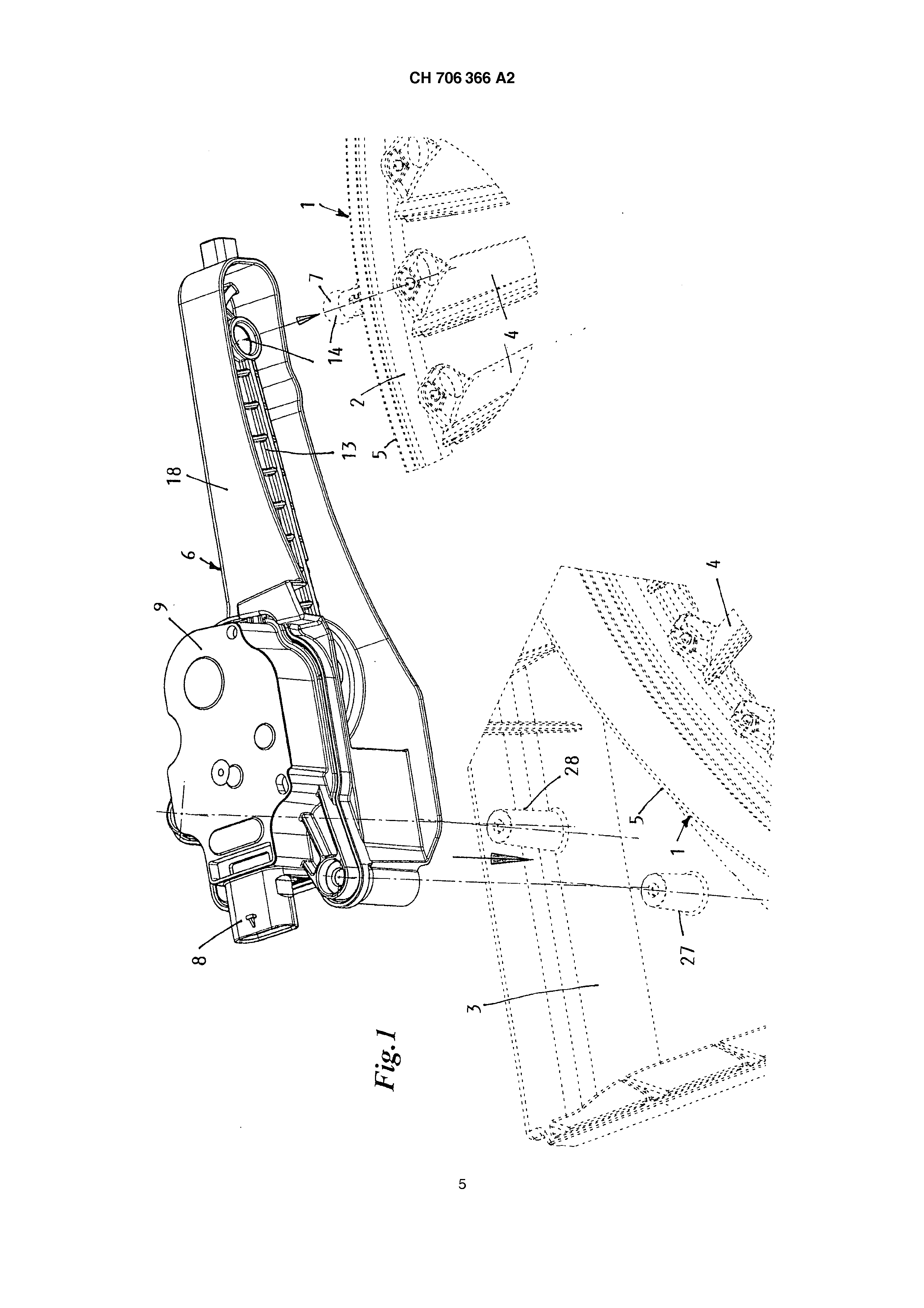
[0001] Shutter for the radiator of a motor vehicle also in a circular channel of a Kühlerrahmens around their longitudinal axis tiltable stored, radially arranged lamellas, which are coupled with a tension ring enclosing the channel for the execution of a lagging between an open and closed position of the shutter in the range of their radially outside end, whereby the tension ring is articulated with a Stellstange one at the Kühlerrahmen of fastened control drive coupled at a place of its extent. Shutters of this kind are for example admit by the DE3 905,349, DE 4,414,893 and EP1 974,974. The use of a vacuum timing control for a control drive has among other things also the disadvantage that apart from the technical measures, including a source of negative pressure, suggested there, and vacuum pipings, which necessities suppress only with running engine will maintain can, so that opening the shutter when incorrect turning the internal combustion engine of the motor vehicle off and a reasoning cannot be controlled to the storage of the warmth of an intentionally turned off internal combustion engine according to plan. Also it is unfavorable that the adjusting force of a vacuum timing control is dependent on the size of their diameter, so that it needs an accordingly large designation of location at the edge of the shutter and/or at the Kühlerrahmen. By the DE10 047,952 it is further well-known, the movement of the tension ring of a shutter of the kind initially specified by means of a short of steering bent, directly lever arm of an actuator affecting the tension ring by intervening in a drilling of the tension ring, in order the lamellas of the shutter by a quarterly revolution from openly up to the closed position the shutter to move. In addition this actuator must be adjustably stored for the execution of a balance movement and is coupled with thermostats. The task is appropriate for the invention at the basis a shutter of the kind initially specified to find, whose control drive exhibits a high insurance of operation during space saving building method and arrangement and which on the tension ring can exercise high adjusting forces. In addition it should be adaptable in manufacture-moderately simple way at differently dimensioned shutters and their Kühlerrahmen, so that it can replace a usual negative pressure position box also without constructional changes at these. The solution of the task of the invention takes place via the fact that the control drive exhibits a selflocking gear motor, whose output shaft with a crank is coupled, whose is connected to the output shaft cleared away end with a Stellstange by a joint, whose is coupled with the tension ring the crank cleared away end. In the following the invention tied up one described in the designs represented of remark example more near. It shows: Fig. ranges of the Kühlerrahmens and the shutter, and Fig determined 1 a perspective overall display of the control drive also by line lines suggested, for its assembly. 2 an exploded view of the control drive with single representation of its actuator, its crank, its Stellstange and an adapter housing. The radiator shutter 1 serves opening and closing a circular, air duct 2 adjacent on the radiator of a motor vehicle, which is intended within also Kühlerrahmens 3 a called radiator trim. For this the air duct encloses 2 numerous radially arranged shutter lamellas 4. tiltable stored in it. For the execution opening and reasoning serving lagging of the lamellas 4 the air duct 2 more enclosing a tension ring 5 adjustable in its circumferential direction is intended. The kind of the effect of the tension ring 5 on the lamellas 4 is for example in the EP 1,974,974 more near descriptive just like the entire execution of the shutter. For the coupling with the invention-substantial drive 6 of the tension ring 5 of the shutter fastened or angeformt a Kopplungselement is e.g. in form of a coupling tap 7 to the outside extent of the tension ring 5. The control drive 6 has one over an electrical plug-in connection 8 supplied stepping motor, which is enclosed with a row of not-represented gear wheels in a common flat gear case 9, so that its with the crankshaft 10 of a position crank 11 coupled output shaft can receive a high torque. The use of a stepping motor has the advantage that see when starting calibrate can, so that no sensors for the recognition of the position position and no locking are necessary for the final positions of the lamellas. In addition malfunctionings are recognized, so that the lamellas of the shutter 1 are moved with error situations, e.g. in case of failure communication with a controller, into an opened position. By its selflocking characteristics the control drive 6 can hold the lamellas for a temperature control also in intermediate positions. The transmission of the position movement of the position crank 1 1 on the tension ring 5 of the shutter is made by a first joint 12 on a Stellstange 13, whose is coupled this first joint 12 cleared away end over second, planned at their outside end, the coupling tap 7 exhibiting joint 14 with the tension ring 5. Preferably these two joints 12 and 14 are implemented as ball joint, so that in two to each other senkrechten levels taking place the movement of the Stellstange is executable, i.e. according to the lagging of the position crank 11 and the curved course of the tension ring 5 without Biegeverformungen. In each case a ball engaged 15 in a Gelenkpfanne 16, and both are einstückig trained with the position crank 1 1 and/or the Stellstange 13 in plastic spraying technology. The ball 15 of the first joint is preferably intended at one the crankshaft 10 of the position crank 1 1 against-arranged short tap 17, so that the position crank 1 1 cooperating with the Stellstange 13 elbow lever-like would drive an unhindered rotating motion out can. Additionally this can be limited also through at the pitman housing of 18 attacks intended for the controlling of a maximum regulating distance over the stepping motor, e.g. according to a crank turn by 180°. This elbow lever-like movement with in relation to the position crank 11 several times longer a Stellstange 13, in relation to a short position crank 11 relative according to the maximum regulating distance of the Stellstange 13, leads to high adjusting forces, in particular in the two extreme positions of the shutter lamellas and a relatively fast position movement in the intermediate positions of the lamella rotating motion. The length of the Stellstange 13 corresponds for example the 3bis 6-fachen to length of the position crank 11, so that it extends approximate tangential for the extent of the tension ring 5 and influences with optimally arranged force component to the tension ring 5. For an optimal positioning of the control drive 6 relative to the coupling tap 7 of the tension ring thus the length of the Stellstange 13 including one associated housing 18 can be selected differently and be adapted to the respective spatial conditions. In order to protect and avoid also around an endangerment by it with work in the engine compartment of the vehicle the position mechanics of the shutter consisting of the position crank 11 and the Stellstange 13 with their ball joints 12.14 against contamination or mechanical effects, is this in one additionally to the gear case 9 of the control drive enclosed, itself along the extent of the tension ring 5 extended 6 intended, elongated, the length of the Stellstange 13 adapted pitman housings 18. For a simple assembly of the control drive 6 adjacent on the extent of the tension ring 5 a flange connection is intended, whose enclose together lying flange 19, 20 an opening 21, by which through the ball 15 of the position crank 11 with the Gelenkpfanne 16 of the Stellstange 13 in interference be brought can between the gear case 9 and the pitman housing 18. For material-saving production of the be enough-strained pitman housing these ridges numerous in lattice-like arrangement have 18 and the Stellstangel3 in plastic spraying technology. For a rigid attachment of the control drive 6 at the Kühlerrahmen 3, relative to turningmobile tension ring 5, takes place via two not-represented fixing bolts, which firsthit a corner themselves by screw channels 24, 25, 26 of the pitman housing 18 and the control drive housing 9 through and intervene with their thread in tangs 27, 28 angeformte at the Kühlerrahmen 3. The louver has a set ring (5) articulated at a point on circumference with a positioning rod (13) of a servo drive (6) i.e. stepper motor, that is fastened on a radiator frame (3). The servo drive includes a self-locking gear motor that includes an output shaft to be coupled with a control crank. An end of the control crank is turned away from the output shaft and connected to a positioning rod (13) by a link. An end of the positioning rod is turned away from the control crank and coupled with the set ring. Louver for a motor vehicle radiator with radially arranged fins (4), mounted in a circular channel (2) of a radiator frame (3) so they can be swiveled around their longitudinal axis, which are linked in the area of their radial outer ends with a set ring (5) surrounding the channel for the execution of a swiveling motion between an open and closed position of the louver, wherein the set ring (5) is articulated at one point on its circumference with a positioning rod (13) of a servo drive (6) that is fastened on a radiator frame (3), characterized in that the servo drive (6) has a self-locking gear motor, whose output shaft (10) is coupled with a control crank (11), of which the end that is turned away from the output shaft (10) is connected by way of a link (12) to a positioning rod (13), of which the end that is turned away from the control crank (11) is coupled with the set ring (5). Louver according to Claim 1, characterized in that the positioning rod (13) is longer than the control crank (11) by a multiple of its length. Louver according to Claim 1, characterized in that the positioning rod (13) has a length that is three to six times longer than the control crank (11). Louver according to one of Claims 1 to 3, characterized in that the positioning rod (13) is connected with the set ring (5) by way of a ball joint (14). Louver according to one of Claims 1 to 4, characterized in that the positioning rod (13) is connected to the control crank (11) by way of a ball joint (12, 14). Louver according to Claim 5, characterized in that the ball head (15) or the socket of the ball head (12) is provided on a crank pin (17) extending away from the control crank (11). Louver according to one of Claims 1 to 6, characterized in that between a housing (9) of the servo drive (6) and a crank rod housing (18), a flange connection is provided, the adjacent flanges (19, 20) of which surround an opening (21) through which the control crank (11) extends. Louver according to Claim 7, characterized in that the crank rod housing (18) and the servo drive housing (9) have screw channels (24-26) that are coaxial with each other for holding fastening screw engaging in the radiator frame (3). Louver according to one of Claims 1 to 8, characterized in that the control crank (11), the positioning rod (13) and a housing (18) of the positioning rod (13) are formed of plastic in the injection molding process. Louver according to Claim 9, characterized in that the positioning rod (13) and the housing (18) of the positioning rod (13) have numerous reinforcement ribs (22, 23) in a grid-like arrangement.