MODULAR WALL SYSTEM
The current invention relates to a modular wall system comprising a number of standard elements which are suitable for use in building a wall, said wall system comprising a first set of posts, a second set of posts and a first set of panels, posts from said first set of posts having a common cross section and being arranged to be fastened upright on a support surface, posts from said second set of posts having a common cross section and being arranged to be fastened upright on a support surface and said panels from said first set of panels having a rectangular form with a left side edge, a top edge, a right side edge and a bottom edge and where said left side edge and said right side edge are arranged to be fastened to a first and a second post respectively from said first or second set of posts to support the panel in an upright position between the two posts. In one embodiment, the wall system is suitable for a multipurpose sports arena. One typical application of such multipurpose sports arenas is outdoor playing fields or playing pitches. It should be noted that while the current embodiments disclosed in this specification all relate to wall systems for sports arenas, the wall system according to the current invention could also be used for other purposes. For example in playgrounds, next to walkways, as general fences, etc. A modular wall system should be understood as a system of components where the components can be assembled into different wall configurations. In other words, the system comprises different elements or different modules which can be joined in different ways to provide different wall structures. It should be noted that a manufacturer might have two or more different modular wall systems. For example, the manufacturer could have one wall system with aluminium components and another wall system with steel features. However, the components of one system will not be designed to be used with the components of the other system. Within a system, the different components will be designed to be used in different configurations. Wall systems for sports arenas are well known in the art. Different manufacturers have different offerings. Different wall systems for sports arenas are therefore available in many different levels of quality, different types of materials and different sizes. Likewise, sports arenas can have many different purposes. For example, one sports arena could be suitable for playing floor ball, another could be suitable for playing soccer, another for playing basketball, etc... It is therefore often desired to provide a sports arena which can be used for different purposes. Customers have therefore become accustomed to being able to choose between many different options. As a manufacturer of wall systems for sports arenas, if all the customers' requirements and desires should be met, it would require a large number of different variants. This is expensive to manufacture, keep in stock and complicated for the client to order. Hence, a first aspect of the current invention is to provide a modular wall system as mentioned in the introductory paragraph which reduces the number of necessary variants to be kept in stock while still providing a large number of options for the client. A second aspect of the current invention is to provide a modular wall system as mentioned in the introductory paragraph which provides for an option which has an attractive design and an option which has a lower cost. A third aspect of the current invention is to provide a modular wall system as mentioned in the introductory paragraph which provides for a system which is easy to assemble. These aspects are provided at least in part by a modular wall system as mentioned in the introductory paragraph and comprising the features of claim 1. Additional interesting embodiments are disclosed by the features mentioned in the claims which are hereby incorporated in the description and by the additional features discussed below. In one embodiment, the panels have a thickness T and the posts have an outwardly facing surface arranged between the support surfaces and the minimum horizontal distance from the support surfaces of the posts to said inwardly facing surface is less than 120% of the thickness of the panels. In one embodiment, the distance is less than 110% of the thickness of the panels or less than or equal to 100%. Typically, the assembled wall structure will be surrounding a playing area or area of interest. One surface of the wall will be facing the area of interest and another surface will be facing away from the area of interest. In the understanding of the above "inwardly facing surface", the surface should be understood as the surface which faces the area of interest. As such in one embodiment, the perpendicular distance relative to the plane of the panels from the inwardly facing support surface of the posts to the inwardly facing surface of the posts facing the area of interest which is closest to the area of interest will be less than 120%, less than 110% or less than or equal to 100% of the thickness of the panels. In one embodiment, the posts from the first and/or second set of posts could be arranged such that when two panels are connected to the post, a surface of a first panel, a surface of a second panel and a surface of the post are arranged essentially flush and in a common plane. This would be similar to the case described above where the distance and the thickness are identical. In one embodiment, the aluminium shell could be an extruded aluminium profile. In one embodiment, the aluminium shell could be a closed extruded aluminium profile. In one embodiment, the aluminium shell could be provided with a cavity arranged outside the inner steel core and behind the support surfaces and running the length of the post. In one embodiment, rails could extend along the entire length of the posts from the second set of posts. In one embodiment, the rails could be arranged on the inwards facing surfaces of the supporting surfaces. By inwards facing surfaces could be understood as surfaces facing the area of interest as discussed above. In one embodiment, the rails could be suitable for receiving a T-nut like fitting. In one embodiment, the posts from the second set of posts could comprise a recess running along the longitudinal axis of the post, said recess being suitable for accepting self-tapping screws. It should be emphasized that the term "comprises/comprising/comprised of" when used in this specification is taken to specify the presence of stated features, integers, steps or components but does not preclude the presence or addition of one or more other features, integers, steps, components or groups thereof. For example, in the claims it is stated that the system comprises a first and a second set of posts. However, the system could comprise any number of sets of posts. In the following, the invention will be described in greater detail with reference to embodiments shown by the enclosed figures. It should be emphasized that the embodiments shown are used for example purposes only and should not be used to limit the scope of the invention.
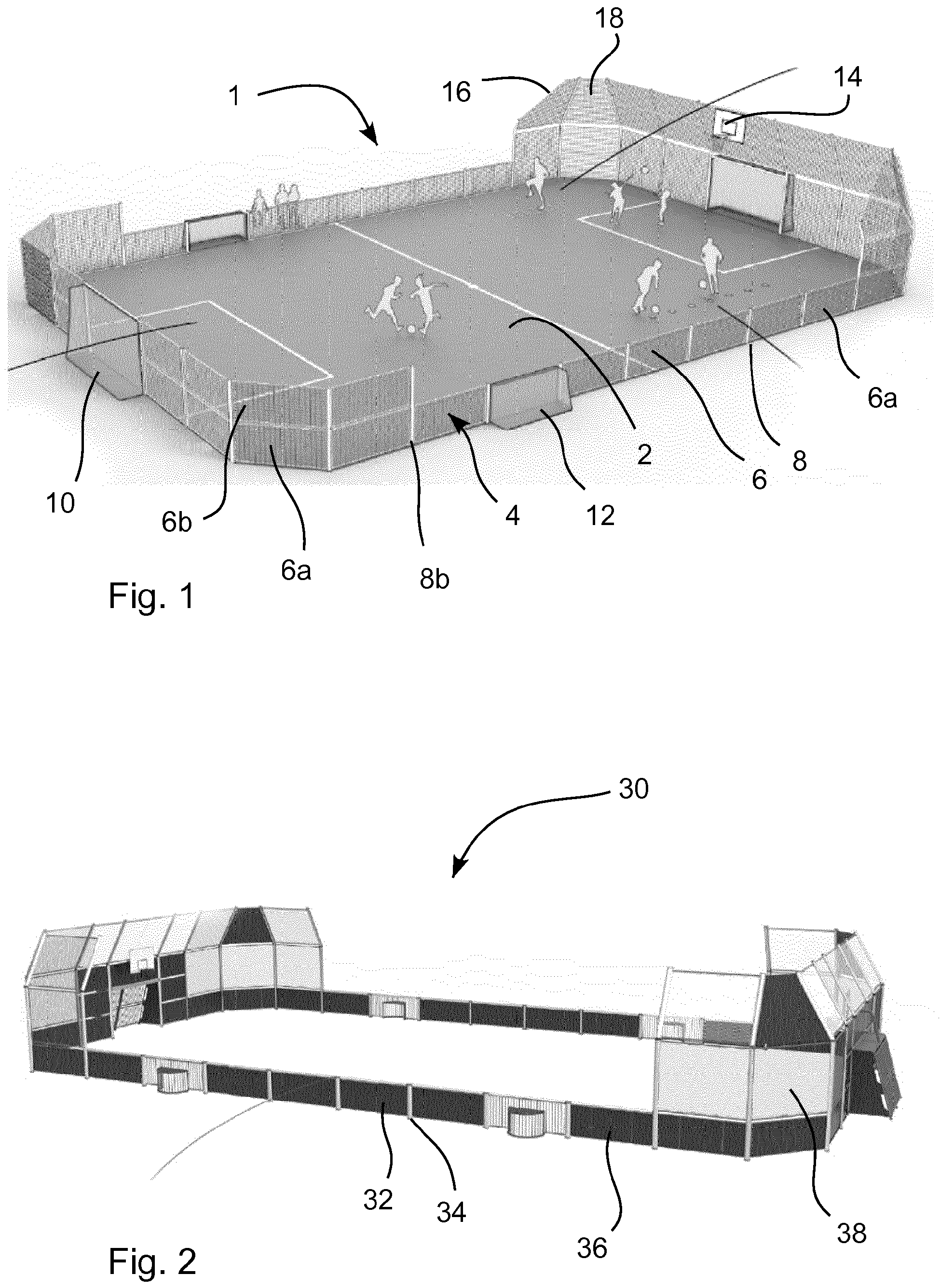
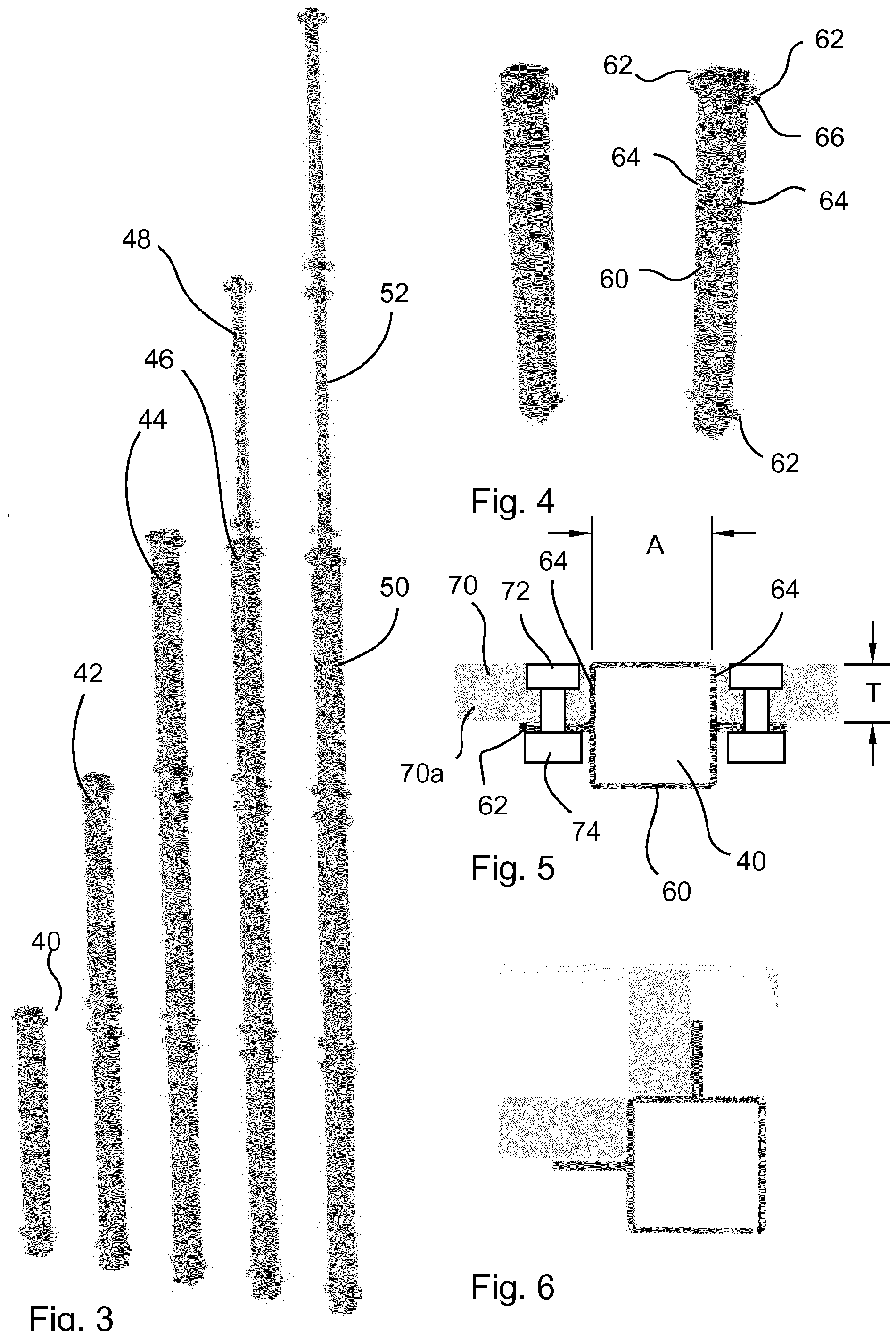
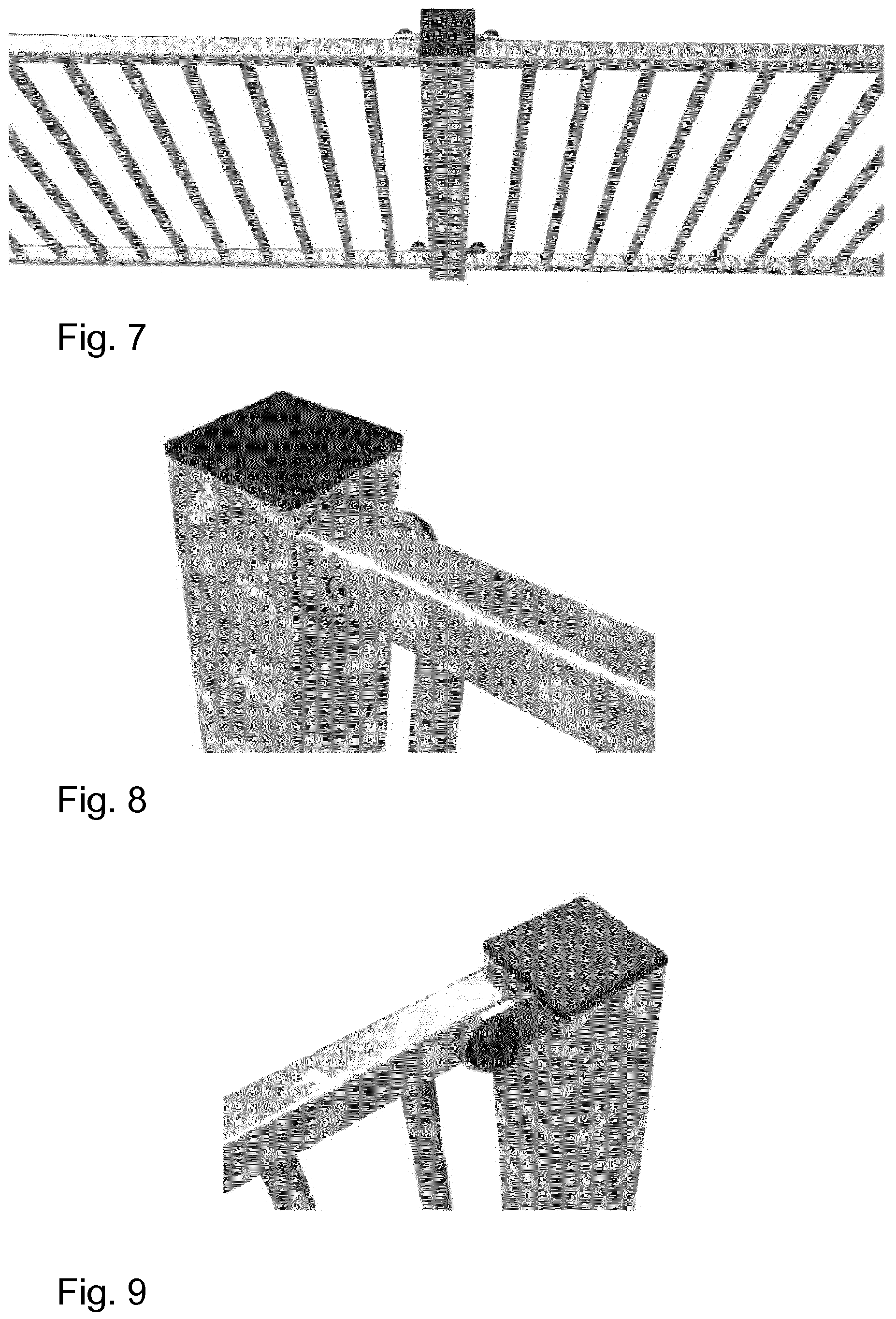
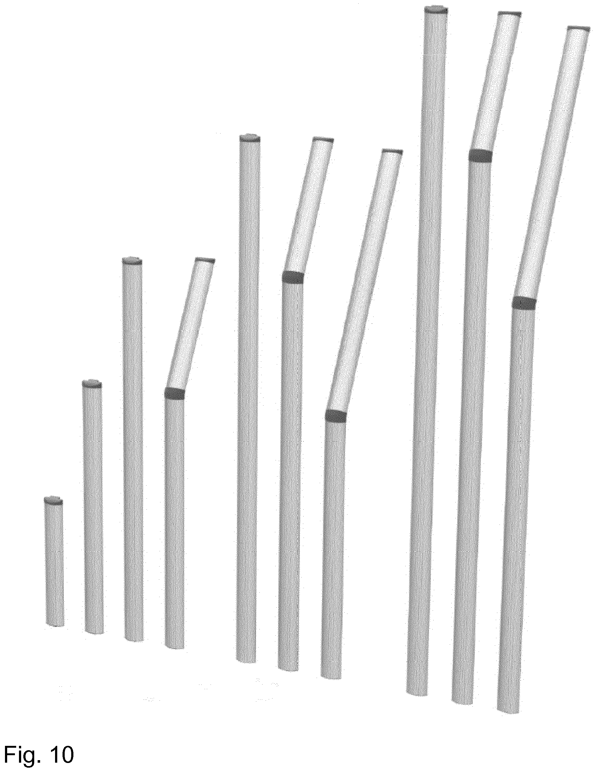
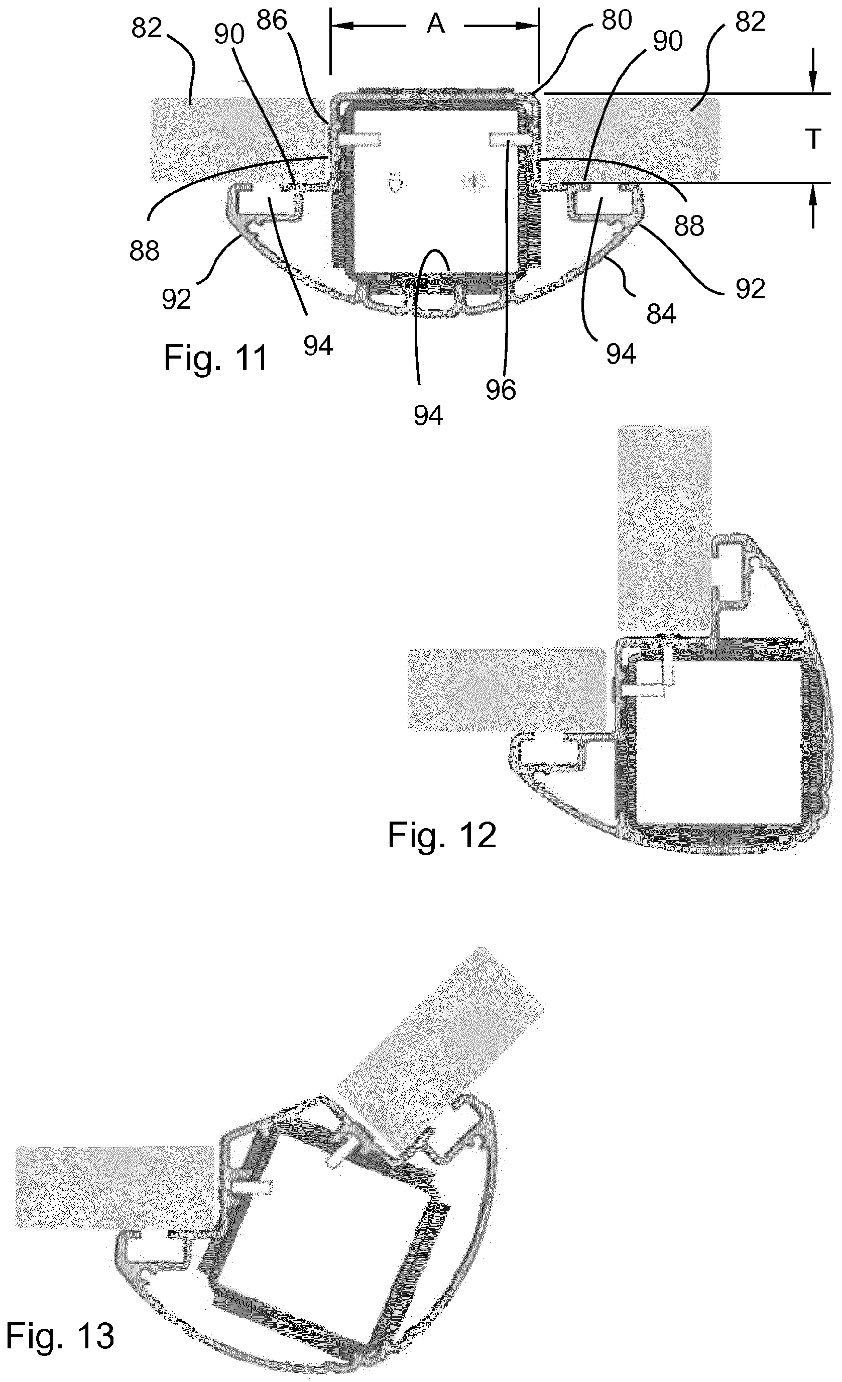
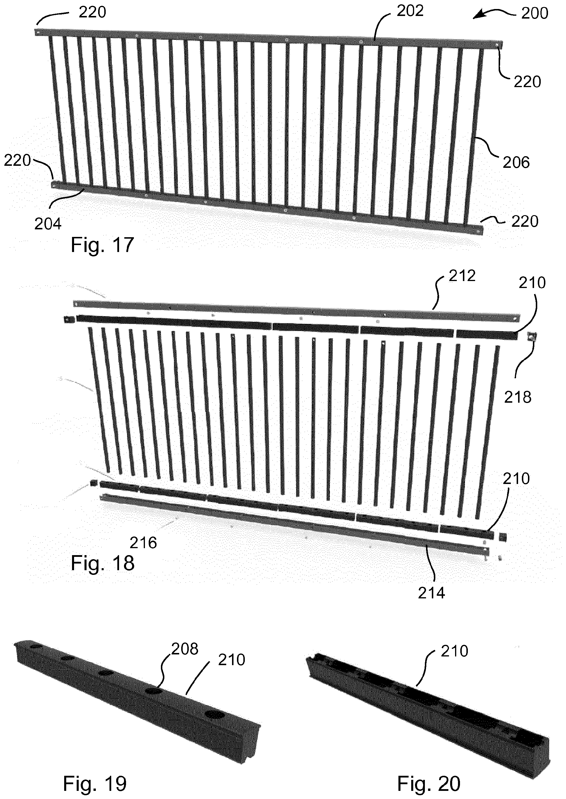
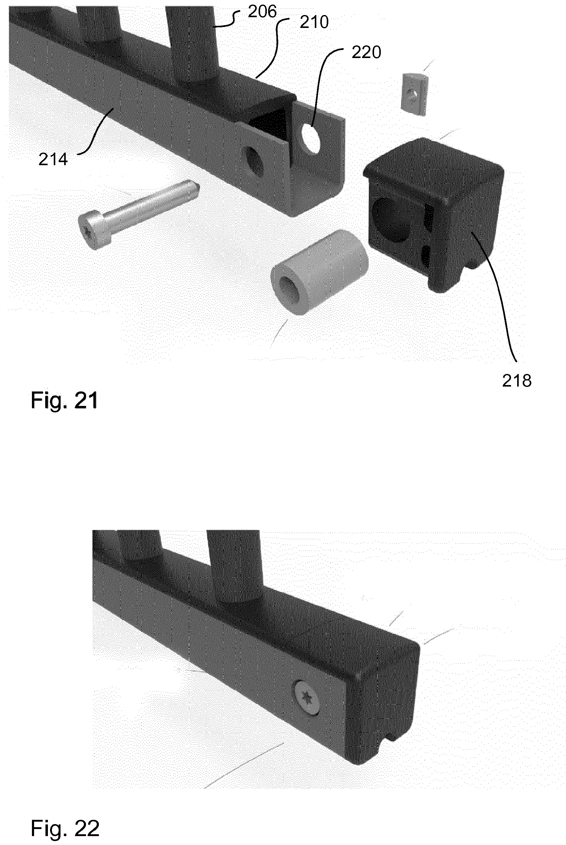
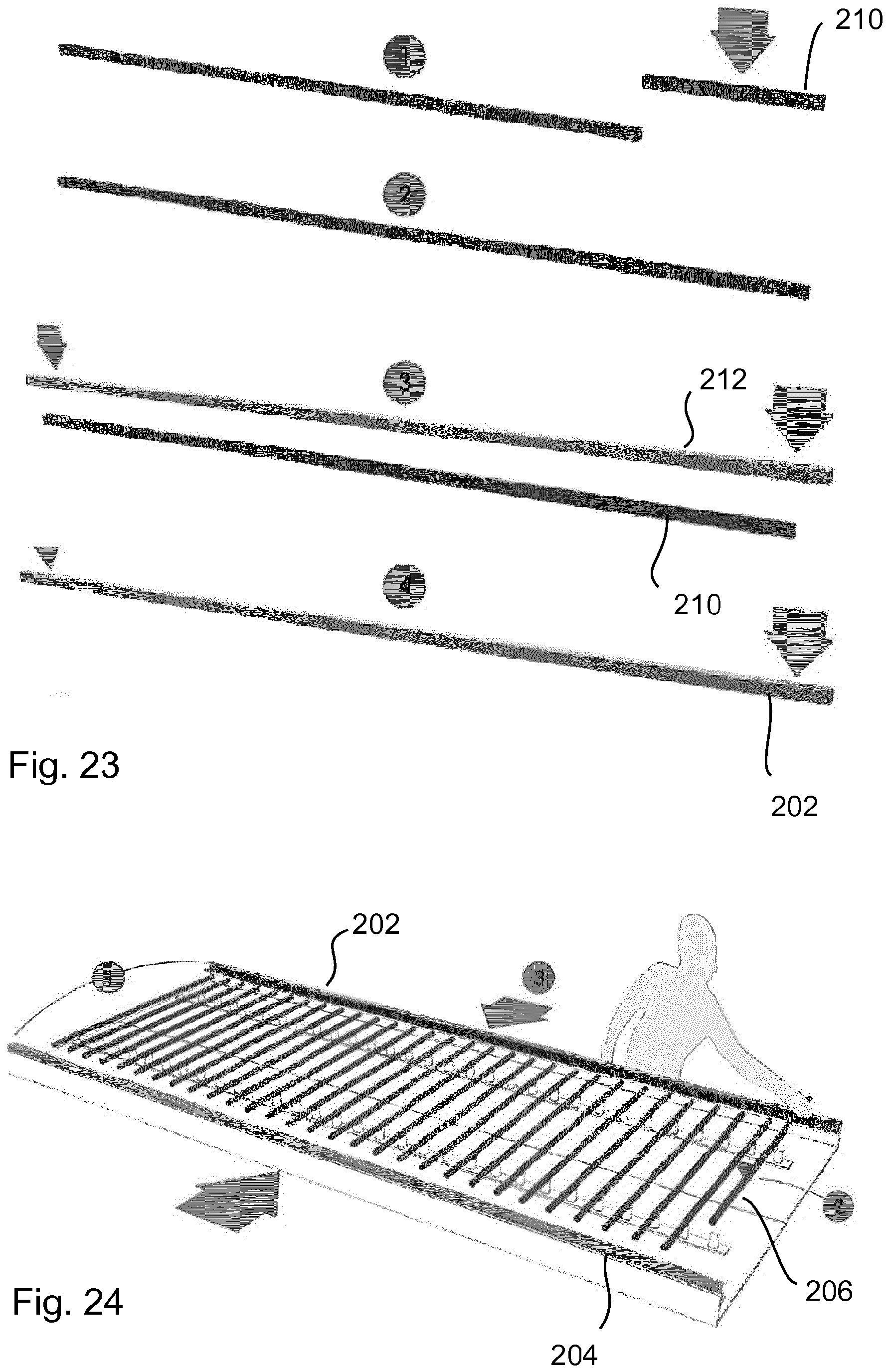
In the sports arena of In other embodiments (not shown) it could be imagined that even longer posts were used and a net was connected to the top of the posts to cover the entire sports arena to prevent high flying balls. In the sports arena of The sports arena 30 of In the sports arena 30 of It should be noted that the sports arenas of The four flanges are all provided in the same plane. The surface of the flanges facing the playing area can be called a support surface or an inwardly facing support surface for the panels. As can be seen, the width of the central section 60 of the post is shown as A. As the two side edges of the panels are arranged to abut the sideways facing surfaces 64 of the central section, the distance between the side edges of adjacent panels will be the same as the width of the post. In this case, the two sideways facing surfaces 64 of the post can be understood as a two vertically extending surfaces which function as a panel spacing arrangement since the two surfaces 64 ensure the spacing of the panels. The spacing between adjacent panels is also determined by the spacing by the holes 66 in the flanges of the post and the holes in the left and ride side of the panels. If the position of the holes in the panels are fixed and the position of the holes in the flanges are fixed, then the distance between adjacent panels will always be the same. In this case, the holes in the panels and the holes in the flange elements can also be thought of as a panel spacing arrangement. It can also be seen from The left post in As can be seen from Likewise, the aluminium portion has two inwardly facing supporting surfaces 90 which face the playing area, just like the two flanges of the steel version. However, instead of being flanges, the inwardly facing surfaces are formed as a portion 92 of the extruded aluminium profile element. Furthermore, rails 94 are formed in the surfaces into which T nuts can be placed to easily connect panels to the posts. It can also be noted that the distance between the rails is identical to the distance between the holes in the flanges in the steel version. In this way, the spacing between panels in the steel post version and the aluminium post version will be identical. In order to provide strength to the aluminium posts, an inner steel core 94 is provided inside the extruded aluminium profile. The inner steel core is typically slid into the aluminium profile and then screws 96 are placed through the side of the aluminium profile to engage with the inner steel core. This can be seen in Since the aluminium profile is extruded, it is easy to add cosmetic details, such as arcs and ribs. Likewise, it is easy to add channels in the profile through which electrical cables, etc can be run. It should be clear from the above, that the same panels can be mounted to both the steel posts and the aluminium posts. Likewise, since the spacing between panels is held constant, no matter if the steel or the aluminium posts are used, a customer can mix and match between the steel and aluminium posts as desired. In addition, two very different designs of posts can be provided while still making use of common panels. In this way, the number of possibilities for the client to choose are increased while the number of variants which need to be kept in stock and manufactured are decreased. In the language of the claims, the steel posts can be said to be a part of the first set of posts and the aluminium posts can be said to be a part of the second set of posts. Likewise, the posts shown in In one embodiment of assembling a wall structure, holes are dug at relevant positions around the playing field. Posts are then inserted into the holes, but without fastening them yet. Panels are then connected to the posts until the wall structure is completed. The panels are then supported above the playing area and adjusted until the panels are level and arranged properly. At this point, the posts are essentially floating since they are being held in place by the panels. Once everything looks correct, cement or concrete is poured into the holes to fasten the posts to the support surface. Other processes to assemble the wall structure can also be used. It is to be noted that the figures and the above description have in some cases shown the example embodiments in a simple and schematic manner. Many of the specific mechanical details have not been shown or described since the person skilled in the art should be familiar with these details and they would just unnecessarily complicate this description. For example, many of the specific materials used and the specific manufacturing procedures have not been described in detail since it is maintained that the person skilled in the art would be able to find suitable materials and suitable processes to manufacture the elements according to the current invention. Likewise, many features of the figures have not been described in detail. However, the figures can be used as a teaching for the person skilled in the art and features can therefore be derived from the figures. The current specification also discloses a second invention related to a panel for use in a wall system, said panel comprising a first horizontal elongated element, a second horizontal elongated element and at least one vertically extending element arranged between the first and second horizontal elements and fastened to said first and second horizontal elongated elements, suitable for use in assembling a wall for a sports arena. While the embodiments disclosed in the current specification relate to panels for walls in sports arenas, it should be clear that the panels according to this second invention can be used in any number of other applications. Some non-limiting examples are: playgrounds, bridges, general fencing, etc Panels suitable for use in wall assemblies in a sports arena are well known in the art. Typically these panels comprise wooden sections or welded steel structures comprising a welded frame with metal horizontal elongated elements and vertically arranged rods/slats welded to the horizontal elongated elements. These structures are often time consuming and therefore expensive to assemble. Furthermore, when a sudden force is applied to the known panels, for example when a ball hits a panel, then the panel will vibrate and/or rattle, generating undesired noise. It is therefore a first aspect of this second invention, to provide a panel which is fast to assemble. A second aspect of the second invention is to provide a panel which can be assembled without welding or with a reduced amount of welding. A third aspect of this second invention is to provide a panel suitable for wall assembly in a sports arena which absorbs force and reduces noise. These aspects are provided at least in part by providing a panel according to claim 1. Additional interesting embodiments are disclosed by the features mentioned in the items below. In the following, the second invention will be described in greater detail with reference to embodiments shown by the enclosed The panel 200 of In the embodiment shown in In the embodiment shown in Once the U shaped channels and resilient elements are joined together, the cross pieces can be moved into another form (see In It is to be noted that the figures and the above description have in some cases shown the example embodiments in a simple and schematic manner. Many of the specific mechanical details have not been shown or described since the person skilled in the art should be familiar with these details and they would just unnecessarily complicate this description. For example, many of the specific materials used and the specific manufacturing procedures have not been described in detail since it is maintained that the person skilled in the art would be able to find suitable materials and suitable processes to manufacture the elements according to the current invention. The second invention is defined in more detail via the following items which could be converted to claims in a potential divisional application. Item 1. A panel for use in a wall system, said panel comprising a first horizontal elongated element, a second horizontal elongated element and at least one vertically extending element arranged between the first and second horizontal elements and fastened to said first and second horizontal elongated elements, characterized in that the panel further comprises an first resilient element between the first horizontal element and the vertically arranged element and in that the panel further comprises a second resilient element between the second horizontal element and the vertically arranged element. Item 2. A panel according to item 1, characterized in that the first resilient element comprises a recess into which an end portion of the vertically extending element is engaged and in that the second resilient element comprises a recess into which an opposite end portion of the vertically extending element is engaged. Item 3. A panel according to item 1 or 2, characterized in that the panel comprises a plurality of vertically extending elements, said plurality of vertically extending elements being arranged spaced apart, parallel to each other and co planar. Item 4. A panel according to item 3, characterized in that the first and second resilient elements comprise a plurality of recesses which matches the plurality of vertically extending elements. Item 5. A panel according to any one of items 1 to 4, characterized in that the first and/or second resilient elements are comprises of a plurality of elongated elements which are arranged in-line with each other. Item 6. A panel according to any one of items 1 to 5, characterized in that the first horizontal elongated element comprises a downwardly open channel and in that the first resilient element is accessible through the downwardly open channel and in that the second horizontal elongated element comprises an upwardly open channel and in that the second resilient element is accessible through the upwardly open channel. Item 7. A panel according to item 6, characterized in that the downwardly open channel is a downwards facing U shaped channel and in that the upwardly open channel is an upwards facing U shaped channel. Item 8. A panel according to item 6, characterized in that the downwardly open channel is a sideways facing U shaped channel to allow the resilient element to be added from the side and that the channel comprises an opening in the bottom of the channel to allow the vertically extending elements to engage with the resilient element. Item 9. A panel according to any one of items 1 to 8, characterized in that the vertically extending element is press fitted into the first resilient element and the second resilient element. Item 10. A panel according to any one of items 1 to 9, characterized in that the first and second resilient elements are press fitted into the first and second horizontal elongated elements. Item 11. A method of assembling a panel according to any one of items 1 to 10, characterized in that the method comprises the steps of
Item 12. A method according to item 11 characterized in that in step g) a plurality of vertically extending elements are provided and in that in steps h) and i) the plurality of vertically extending elements are press fitted into the resilient elements. Item 13. A method according to item 11 or 12 characterized in that the method further comprises the steps of
In one embodiment, instead of press fitting the vertically extending elements into the resilient elements, glue could be provided between the resilient elements and the vertically extending elements. In one embodiment, glue could be arranged in the recesses in the resilient elements and the vertically extending elements could be pressed into the glue in the recesses during assembly. In one embodiment, the resilient elements could be connected to the horizontal elongated elements via glue as well. A third invention which is disclosed in the current specification is a goal assembly suitable for ball sports, said goal assembly comprising a frame defining a goal opening and a net connected to the goal frame and enclosing the goal opening such that balls entering the goal opening are caught by the net, characterized in that the net is made of a flexible steel cable mesh. In one embodiment, the net is made of stainless steel cable mesh. In one embodiment, the net assembly is made from a series of individual steel cables which are joined at regular intervals to adjacent steel cables by clamp elements. A more specific product which is covered by the invention would be an outdoor public sports arena with a goal assembly having a goal opening and a steel cable mesh net assembly covering the goal opening. The cable mesh is similar to a normal rope net which is well known in goal assemblies, for example soccer goals, however, instead of using braided plastic fibres, in this case, the elements of the mesh are thin steel wires braided or twisted together. In this way, a net assembly is provided for a goal which is flexible and behaves like a normal net assembly, but which is vandalism proof and robust enough for use in an outdoor public sports arena. In contrast, in the prior art when a goal assembly is provided, a rope net is used which needs to be replaced at regular intervals due to vandalism. Or a stiff wire net is provided. However, when a ball hits the stiff wire net, the ball rebounds out of the goal assembly which is not desired. Steel cable mesh suitable for use in a goal assembly according to this third invention is well known in the art and is commonly available. Searching on google for "steel cable mesh" discloses many suitable examples. However, this type of net has previously only been used for safety nets, security nets, fencing, etc. It has previously not been imagined that this type of net would be suitable for use in a goal assembly for outdoor public sports arenas. A modular wall system comprising a first set of posts (8), a second set of posts (8b) and a first set of panels (70a), said panels having a left side edge and a right side edge arranged to be fastened to a first and a second post respectively from said first or second set of posts. The posts from the first set of posts are made of steel and in that the posts from the second set of posts are made of aluminium and the panels of the first set of panels and/or the posts of the first and second set of posts comprise a panel spacing arrangement which ensure that the spacing between two adjacent panels which are connected to a post will be the same when using a post from the first set of posts and when using a post from the second set of posts.
A modular wall system comprising a number of standard elements which are suitable for use in building a wall, said wall system comprising a first set of posts, a second set of posts and a first set of panels, posts from said first set of posts having a common cross section and being arranged to be fastened upright on a support surface, posts from said second set of posts having a common cross section and being arranged to be fastened upright on a support surface and said panels from said first set of panels having a rectangular form with a left side edge, a top edge, a right side edge and a bottom edge and where said left side edge and said right side edge are arranged to be fastened to a first and a second post respectively from said first or second set of posts to support the panel in an upright position between the two posts characterized in that the posts from the first set of posts are made of steel and in that the posts from the second set of posts are made of aluminium and in that the panels of the first set of panels and/or the posts of the first and second set of posts comprise a panel spacing arrangement which ensures that the spacing between two adjacent panels which are connected to a post will be the same when using a post from the first set of posts and when using a post from the second set of posts. A modular wall system according to claim 1, characterized in that the panel spacing arrangement comprise two vertically extending supporting surfaces on the posts of both the first and second set of posts which are arranged to abut the side edges of adjacent panels when two panels are assembled with the post and in that the distance and angle between the two opposing supporting surfaces on the posts from the first set of posts and the posts from the second set of posts are the same. A modular wall system according to claim 1 or 2, characterized in that the panel spacing arrangement comprises a set of fastening element openings in the panels from the first set of panels near the left side edge of the panels and a second set of fastening element openings in the panels of the first set of panels near the right side edge of the panels and a first set of fastening element openings in the posts from the first and second set of posts on a left side of the posts and a second set of fastening element openings in the posts from the first and second set of posts on a right side of the posts and in that the horizontal distance between the first set of fastening element openings and the second set of fastening element receiving openings is the same for posts from the first set of post and for posts from the second set of posts. A modular wall system according to any one of claims 1 to 3, characterized in that the posts from the first set of posts and the posts from the second set of posts both comprise a left inwardly facing support surface extending from a left side of the posts and a right inwardly facing support surface extending from a right side of the posts, said left and right inwardly facing support surfaces having normal vectors which are perpendicular to a longitudinal axis of the post, said inwardly facing support surfaces of the posts being arranged to support a surface of the left and right side edges of the panels when the panels are connected to a post. A modular wall system according to claim 4, characterized in that the panels have a thickness T and in that the posts have an inwardly facing surface arranged between the support surfaces and in that the minimum horizontal distance from the inwardly facing support surfaces of the posts to said inwardly facing surface of the posts is less than 120% of the thickness of the panels. A modular wall system according to any one of claims 1 to 5, characterized in that said posts from said first and/or second set of posts are arranged such that when two panels are connected to the post, an inwardly facing surface of a first panel, an inwardly facing surface of a second panel and an inwardly facing surface of the post are arranged essentially flush and in a common plane. A modular wall system according to any one of claims 1 to 6, characterized in that the wall system further comprises a third set of posts which comprises posts having two inwardly facing support surfaces which are arranged at an angle to each other which is equal to or between 90 and 180 degrees. A modular wall system according to any one of claims 1 to 7 characterized in that the posts from the second set of posts comprise an aluminium shell and an inner steel core. A modular wall system according to claim 8 characterized in that the aluminium shell is fastened to the inner steel core with screws which pass through the aluminium shell and engage a surface of the inner steel core at an angle which is perpendicular to said surface. A modular wall system according to any one of claims 1 to 9, characterized in that the posts from the second set of posts comprise rails arranged parallel to the longitudinal axis of the post. A modular wall system according to any one of claims 1 to 10 characterized in that said first set of panels comprises a panel comprising a first horizontal elongated element, a second horizontal elongated element and at least one vertically extending element arranged between the first and second horizontal elements and fastened to said first and second horizontal elongated elements, and in that the panel further comprises an first resilient element between the first horizontal element and the vertically arranged element and in that the panel further comprises a second resilient element between the second horizontal element and the vertically arranged element. A modular wall system according to claim 11, characterized in that the first resilient element comprises a recess into which an end portion of the vertically extending element is engaged and in that the second resilient element comprises a recess into which an opposite end portion of the vertically extending element is engaged.Description of related art
Summary of the invention
Brief description of the drawings
Detailed description of the embodiments