REFRIGERATING APPARATUS
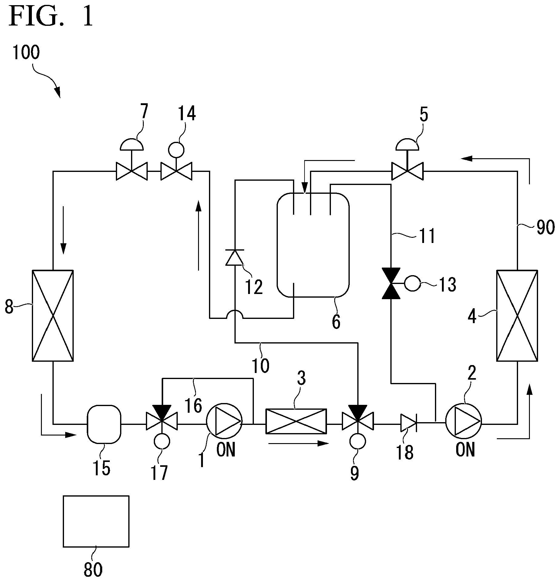
The present disclosure relates to a refrigerating apparatus. A typical refrigerating apparatus includes a compressor, a condenser, an expansion valve, and an evaporator. The high-temperature and high-pressure gaseous refrigerant produced by the compressor is first sent to the condenser. In the condenser, heat exchange between the refrigerant and air is performed, and the refrigerant becomes a high-temperature and high-pressure liquid refrigerant. Thereafter, by passing through the expansion valve, the temperature and pressure of the refrigerant are lowered, and the refrigerant becomes a low-temperature and low-pressure liquid refrigerant. Further, by exchanging heat with air in the evaporator, the refrigerant becomes a low-temperature and low-pressure gaseous refrigerant. In this process, the temperature of the space where the condenser or evaporator is installed is adjusted. Here, in order to improve the output of the refrigerating apparatus, in recent years, a two-stage compression configuration in which a plurality of compressors is arranged in series may be adopted (see When the intermediate heat exchanger as described above is provided, if the outside air temperature is excessively low, the liquid refrigerant may remain in the intermediate heat exchanger. If this liquid refrigerant is sent to the high-pressure side compressor as it is when the refrigerating apparatus is started, liquid compression occurs, which affects the stable operation of the compressor. The present disclosure has been made to solve the above problems, and an object of the present disclosure is to provide a refrigerating apparatus that can be operated more stably. In order to solve the above problems, a refrigerating apparatus according to the present disclosure includes a main circuit that is a circulation passage through which a refrigerant flows, a first compressor and a second compressor that are arranged in series on the main circuit, an intermediate heat exchanger that is disposed between the first compressor and the second compressor, a condenser that is disposed on a downstream side of the second compressor, a first expansion valve that is disposed on a downstream side of the condenser, a receiver that is disposed on a downstream side of the first expansion valve, a second expansion valve that is disposed on a downstream side of the receiver, an evaporator that is disposed on a downstream side of the second expansion valve, a three-way valve provided between the intermediate heat exchanger and the second compressor on the main circuit, a first bypass passage that couples the three-way valve and the receiver, a second bypass passage that couples the receiver, the three-way valve, and the second compressor, a check valve that is provided in the first bypass passage and allows the refrigerant to flow only in a direction from the three-way valve toward the receiver, a first solenoid valve that is provided in the second bypass passage and switches over to an open state of the second bypass passage, and a second solenoid valve that is provided between the receiver and the second expansion valve in the main circuit and switches over to an open state of the main circuit. According to the present disclosure, it is possible to provide a refrigerating apparatus that can be operated more stably. Hereinafter, a refrigerating apparatus 100 according to an embodiment of the present disclosure will be described with reference to As shown in The main circuit 90 is filled in a state of a refrigerant in a liquid or a gas. The first compressor 1 and the second compressor 2 are arranged in series on the main circuit 90. That is, the discharge side of the first compressor 1 faces the suction side of the second compressor 2. As the first compressor 1 and the second compressor 2, for example, a scroll compressor, a rotary compressor, or a rotary compressor can be used. In the following description, on the main circuit 90, the side on which the second compressor 2 is located when viewed from the first compressor 1 may be referred to as a downstream side, and the opposite side thereof may be referred to as an upstream side. The first three-way valve 9 and the second check valve 18 are arranged in this order on the downstream side of the first compressor 1. The details of the first three-way valve 9 will be described later. The second check valve 18 is configured to allow the refrigerant to flow only in the direction from the upstream side toward the downstream side. The intermediate heat exchanger 3 is disposed between the first compressor 1 and the second compressor 2. In the intermediate heat exchanger 3, the high-temperature refrigerant discharged from the first compressor 1 is cooled by exchanging heat with the external air in the intermediate heat exchanger 3 and then sent to the second compressor 2. The intermediate heat exchanger 3 is provided for improving the efficiency of the refrigerating apparatus 100. The condenser 4 is disposed on the downstream side of the second compressor 2. The condenser 4 is a heat exchanger for exchanging heat between the external air and the refrigerant. A fan (not shown) is provided in the vicinity of the condenser 4, and it is possible to forcibly exchange heat between the air and the refrigerant. The high-temperature and high-pressure gaseous refrigerant produced by the second compressor 2 is condensed by passing through the condenser 4 and becomes a high-temperature and high-pressure liquid refrigerant. The first expansion valve 5 is provided on the downstream side of the condenser 4. The high-temperature and high-pressure liquid refrigerant supplied from the condenser 4 passes through the first expansion valve 5, the pressure and temperature decrease, and the refrigerant becomes a low-temperature and low-pressure liquid refrigerant. The receiver 6 is coupled to the downstream side of the first expansion valve 5. The receiver 6 is a container for storing at least a part of the liquid refrigerant that has passed through the first expansion valve 5. The amount of liquid refrigerant that can exist in the main circuit 90 varies depending on the operating conditions. The receiver 6 is provided to cope with this variation. The second solenoid valve 14 and the second expansion valve 7 are arranged in this order on the downstream side of the receiver 6. As will be described in detail later, the second solenoid valve 14 is provided to switch over to the open state of the main circuit 90. The second expansion valve 7 is provided to further reduce the temperature and pressure of the low-temperature and low-pressure liquid refrigerant that has passed through the receiver 6. The first expansion valve 5 and the second expansion valve 7 are electromagnetic expansion valves that can be switched between the open and closed states by an electric signal from the outside. The evaporator 8 is provided on the downstream side of the second expansion valve 7. The evaporator 8 is a heat exchanger for exchanging heat between the external air and the refrigerant. A fan (not shown) is provided in the vicinity of the evaporator 8 so that heat exchange between air and the refrigerant can be forcibly performed. The low-temperature and low-pressure liquid refrigerant that has passed through the second expansion valve 7 evaporates by exchanging heat with the outside air when passing through the evaporator 8 and becomes a low-temperature and low-pressure gaseous refrigerant. The accumulator 15 is provided on the downstream side of the evaporator 8. The accumulator 15 is a container for storing the liquid refrigerant that could not be completely evaporated by the evaporator 8. After the liquid component is removed by the accumulator 15, the gaseous refrigerant is sent to the first compressor 1 again and compressed. By continuously repeating such a cycle (refrigeration cycle), the refrigerating apparatus 100 is operated. The first bypass passage 10 is a passage coupling the first three-way valve 9 and the receiver 6. That is, the first bypass passage 10 branches from the main circuit 90 via the first three-way valve 9 and extends to the receiver 6. The first check valve 12 is provided on the first bypass passage 10. The first check valve 12 is configured to allow the refrigerant to flow only in the direction from the first three-way valve 9 toward the receiver 6. The second bypass passage 11 couples the above-mentioned second check valve 18 and the second compressor 2, and the receiver 6. The first solenoid valve 13 is provided on the second bypass passage 11. The open and closed states of the first solenoid valve 13 can be switched by an electric signal from the outside. The third bypass passage 16 is a passage that bypasses the downstream side of the accumulator 15 and between the first compressor 1 and the intermediate heat exchanger 3. The second three-way valve 17 is provided on the upstream side of the third bypass passage 16. That is, the third bypass passage 16 branches from the main circuit 90 via the second three-way valve 17. The control unit 80 is provided to switch between the open and closed states of each valve device described above and the operating state of the first compressor 1 and the second compressor 2 by an electric signal. Specifically, the control unit 80 can switch between the open and closed states of the first expansion valve 5, the first three-way valve 9, the second three-way valve 17, the first solenoid valve 13, and the second solenoid valve 14. Further, the control unit 80 can place at least one of the first compressor 1 and the second compressor 2 in an operating state and the other in a stopped state. Subsequently, an example of the operation of the refrigerating apparatus 100 will be described. As shown in Here, a part of the gaseous refrigerant may be condensed inside the intermediate heat exchanger 3 to generate a liquid refrigerant. In particular, if the outside air temperature is excessively low, the liquid refrigerant may remain in the intermediate heat exchanger 3. If this liquid refrigerant is sent to the compressor as it is when the refrigerating apparatus 100 is started, liquid compression occurs, which affects the stable operation of the compressor. Therefore, in the present embodiment, as described above, the first bypass passage 10, the second bypass passage 11, and the third bypass passage 16 are provided, respectively. For example, a case where only the second compressor 2 is started will be described. As shown in In this state, the flow of the refrigerant as shown by the arrow in The third bypass passage 16 is placed in an open state in order to prevent the stopped first compressor 1 from being in a reverse pressure state when only the second compressor 2 is started. Further, as another example, when only the first compressor 1 is started, the state is as shown in In this state, the flow of the refrigerant as shown by the arrow in As described above, in the refrigerating apparatus 100 according to the present embodiment, it is possible to remove the liquid refrigerant remaining in the intermediate heat exchanger 3 in advance prior to the normal operation. This reduces the possibility of liquid compression occurring in the second compressor 2. As a result, damage to the second compressor 2 is avoided, and the refrigerating apparatus 100 can be operated stably for a longer period of time. Although the embodiment of the present disclosure has been described in detail with reference to the drawings, the specific configuration is not limited to this embodiment and includes design changes and the like within a range not deviating from the gist of the present disclosure. The refrigerating apparatus 100 described in each embodiment is grasped as follows, for example.
According to the above configuration, when only the first compressor 1 is started, the liquid refrigerant in the intermediate heat exchanger 3 located on the downstream side of the first compressor 1 is pumped through the first bypass passage 10 by the pumping force of the first compressor 1. The liquid refrigerant pumped through the first bypass passage 10 is stored in the receiver 6. In this way, the liquid refrigerant in the intermediate heat exchanger 3 can be recovered to the receiver 6. While preferred embodiments of the invention have been described and illustrated above, it should be understood that these are exemplary of the invention and are not to be considered as limiting. Additions, omissions, substitutions, and other modifications can be made without departing from the scope of the invention. Accordingly, the invention is not to be considered as being limited by the foregoing description and is only limited by the scope of the appended claims. There is provided a refrigerating apparatus (100) that can be operated more stably. The refrigerating apparatus (100) includes a first compressor (1) and a second compressor (2) that are arranged in series on the main circuit (90), an intermediate heat exchanger (3), a condenser (4), a first expansion valve (5), a receiver (6), a second expansion valve (7), an evaporator (8), a three-way valve (9) provided between the intermediate heat exchanger (3) and the second compressor (2), a first bypass passage (10) that couples the three-way valve (9) and the receiver (6), a second bypass passage (11) that couples the receiver (6), the three-way valve (9), and the second compressor (2), a first solenoid valve (13) that switches over to an open state of the second bypass passage (10), and a second solenoid valve (11) that is provided between the receiver (6) and the second expansion valve (7) and switches over to an open state of the main circuit (90).
A refrigerating apparatus (100) comprising:
a main circuit (90) that is a circulation passage through which a refrigerant flows; a first compressor (1) and a second compressor (2) that are arranged in series on the main circuit (90); an intermediate heat exchanger (3) that is disposed between the first compressor (1) and the second compressor (2); a condenser (4) that is disposed on a downstream side of the second compressor (2); a first expansion valve (5) that is disposed on a downstream side of the condenser (4); a receiver (6) that is disposed on a downstream side of the first expansion valve (5); a second expansion valve (7) that is disposed on a downstream side of the receiver (6); an evaporator (8) that is disposed on a downstream side of the second expansion valve (7); a three-way valve (9) provided between the intermediate heat exchanger (3) and the second compressor (2) on the main circuit; a first bypass passage (10) that couples the three-way valve (9) and the receiver (6), a second bypass passage (11) that couples the receiver (6), the three-way valve (9), and the second compressor (2); a check valve (12) that is provided in the first bypass passage (10) and allows the refrigerant to flow only in a direction from the three-way valve (9) toward the receiver (6); a first solenoid valve (13) that is provided in the second bypass passage (11) and is configured to switch over to an open state of the second bypass passage (11); and a second solenoid valve (14) that is provided between the receiver (6) and the second expansion valve (7) in the main circuit (90) and is configured to switch over to an open state of the main circuit (90). The refrigerating apparatus (100) according to claim 1, further comprising:
a control unit (80) that is configured to switch between open and closed states of the first expansion valve (5), the three-way valve (9), the first solenoid valve (13), and the second solenoid valve (14), and to switch over to an operating state of the first compressor (1) and the second compressor (2), wherein the control unit (80) is configured to, when only the second compressor (2) is started, close the first expansion valve (5), open the first solenoid valve (13), and open the three-way valve (9) only in a direction from the main circuit (90) toward the first bypass passage (10). The refrigerating apparatus (100) according to claim 2, whereinField of the Invention
Description of Related Art
SUMMARY OF THE INVENTION
BRIEF DESCRIPTION OF THE DRAWINGS
DETAILED DESCRIPTION OF THE INVENTION
(Configuration of Refrigerating Apparatus)
(Configuration of First Compressor and Second Compressor)
(Configuration of Intermediate Heat Exchanger)
(Configuration of Condenser)
(Configuration of Receiver)
(Configuration of Evaporator)
(Configuration of First Bypass passage, Second Bypass Passage, and Third Bypass Passage)
(Structure of Control Unit)
(Effect in Action)
(Other Embodiments)
<Additional Notes>
According to the above configuration, even when the liquid refrigerant remains in the intermediate heat exchanger 3, the liquid refrigerant can flow to the receiver 6 through the first bypass passage 10 and can be recovered.
According to the above configuration, when only the second compressor 2 is started, the pumping force of the second compressor 2 is transmitted to the receiver 6 through the second bypass passage 11. As a result, the pressure in the receiver 6 is lowered. When the pressure in the receiver 6 is lowered, the liquid refrigerant remaining in the intermediate heat exchanger 3 flows toward the receiver 6 through the first bypass passage 10. In this way, it is possible to recover the liquid refrigerant in the intermediate heat exchanger 3 to the receiver 6.EXPLANATION OF REFERENCES
the control unit (80) is configured to, when only the first compressor (1) is started, close the first expansion valve (5) and the first solenoid valve (13), open the three-way valve (9) only in the direction from the main circuit (90) toward the first bypass passage (10), and open the second solenoid valve (14).