Box filling machine, esp for bottles in cardboard boxes with top and bottom flaps
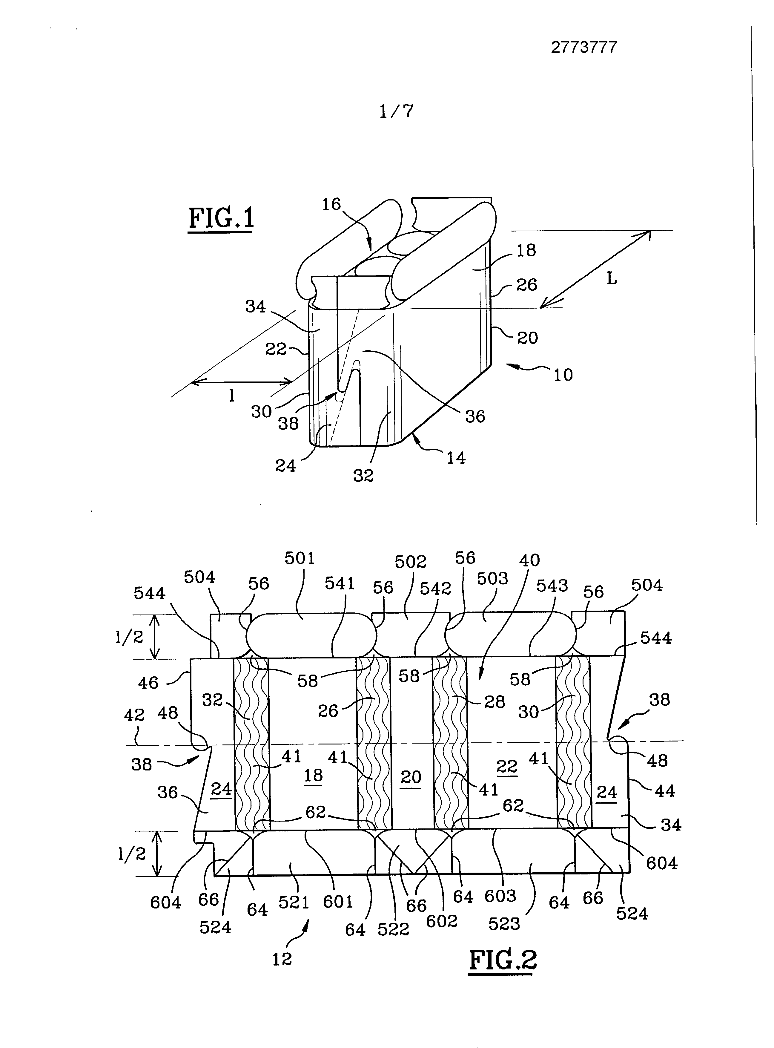
A body cross-section adjusted to the content, for the packaging of objects or batches of shaped objects substantially cylindrical or partly cylindrical, and the required blank made of a sheet material, such as cardboard or corrugated cardboard. The invention also relates to a device boxing, in particular batches of bottles, using preferably said box. The corrugated-board are very gear, they may be conditioned objects or groups of objects, these are introduced from the upper opening of the box. One type well known is the American box. In general, the cases have a square or rectangular cross-section which does not adapt perfectly to the cross-section of the content which has rarely the same shape. Also, the content is not securely held in the case, so that it can move in the body, generating a certain instability during handling. Furthermore, the wedge projections and voids are exposed to external attack and can be easily torn, which affects the presentation and to the protection of packaged objects. On the other hand, for ensuring the integrity of the body, it is necessary to use a corrugated cardboard sheet having good mechanical strength. According in part these drawbacks, the patent application EP-A- [...] provides a box having cut corners, the major side faces are connected together by intermediate side faces. The crate can be reduced by one damaged to the projecting corners and to obtain a gain material. However, the shape of the box does not adapt perfectly to the shape of the content and there still remains empty corners though they are less vulnerable. Also due to the presence of these angles, it is still necessary to have a cardboard sheet having good mechanical strength to have a sufficiently rigid body. The present invention aims to overcome these drawbacks by proposing a blank for making a box whose section is perfectly fitted to the content, by curved shapes, allowing use of the mechanical strength of the content for ensuring the integrity of the body, and which results in a non-negligible gain by volume and by weight of the material used. The present invention also provides a device boxing, in particular batches of bottles, using the box. In a known way, to the chains from the traffic jam, the bottles are introduced, by the opening of the top surface of each box, manually by an operator. This repetitive and very exhausting does not allow boxing rate supported. In the case of using grippers automatic hydraulic or pneumatic pincers, the devices are very costly, complex and the facilities remain reserved for the high rates. The present invention also relates to a device for packaging batches of bottles, semi-automatic or automatic, for introducing the bottles in the box without the need of lifting them. The device is particularly adapted to make the less painful, while increasing the rate boxing, and especially the device finds application in units of small-and medium-sized. To this end, [ ' invention relates to a box for packaging at least one object, in particular batches of shaped objects substantially cylindrical or partly cylindrical, characterized in that it comprises at least two lateral surfaces, connected to each other by portions of reduced stiffness, and at least one bottom. Preferably, one of the side faces is made in two parts connected to each other by connecting means. In a preferred embodiment, the body includes: four side faces of substantially rectangular shape, perpendicular to each other and connected in pairs by areas of lower rigidity, -a base made by bottom flaps attached to the side faces by pressured folding lines, and -a thereon is made by top flaps attached to the side faces by preformed bending lines. The invention also relates to a blank for making, from a sheet, the crate according to the invention, characterized in that it comprises a core provided by the side faces, and the areas of lesser rigidity, alternately arranged, the bottom being connected to at least one of the sides by a fold line pre-formed. In a preferred embodiment, the blank comprises a central part made by the four side faces, between which are interposed the areas of lesser rigidity, the two parts forming the one of the side faces being arranged at each end of the central portion, the top flaps and the bottom flaps, 1/2 length, being arranged on each side of said central portion, and attached to the side faces respectively by the preformed fold lines, and the preformed fold lines, the upper and lower flaps attached to the side face being made astride the two parts. Preferably, the areas of lesser rigidity are obtained by crushing of the sheet in said zones with the aid of a profile adapted crushing. According to another feature, the crushing varies in density and/or depth progressively along the centre axis of the blank so that it is low at the junction of the side faces and areas of lower rigidity, and maximum in the middle of said areas. Advantageously, crushing the profile consists of a series of sinusoidal curves. Finally, the invention also relates to a device for packaging batches of objects, for example, a body according to the invention. Other features and advantages shall become apparent from the description that will follow of the object according to a preferred embodiment, description given by way of example only, with reference to the accompanying drawings on which: -Figure 1 is a perspective view of a case according to the invention with its top flaps open, Figure 2 is a view-flat with a first example of the driving of the body shown figure 1, -Figure 3 is a plan view of the box made from the blank of Figure 2, Figure 4-is a flat view of a second example of the driving of the body shown figure 1, 5A-Figure is a perspective view of a second body according to the invention, 5B-Figure is a view of the blank for making the body shown figure 5A, Figure 6-is a top view of the boxing device according to the invention, Figure 7-is a view in side elevation of the device boxing, -Figures 8A to 8Q show a synoptic operation of the device, and Figure 9-is a view of detail of the pivot axis of the island. On Figures 1,2 and 3, is represented a box 10 according to the invention, in particular for receiving six bottles, and a panel flat 12 required to completion. It is made from a sheet material having rigidity, such as cardboard or corrugated cardboard. The case length and width L for L In a preferred embodiment, the box has a bottom face bottom 14, a top face 16, and four side faces referenced 18, 20, 22 and 24 of substantially rectangular shape, perpendicular to each other and connected in pairs by areas 26, 28, 30, 32 less rigid adaptable to the contents of the box. These lower rigidity regions do not reduce the vertical compressive strength of the body 10 relative to the boxes of the prior art. One of the lateral faces, the face 24, is formed in two parts 34,36 connected by means of link 38 to form from the blank 12, flat, the body 10. These means 38 link can be made by conjugated forms provided on the facing edges of these two parts 34 and 36, as shown in Figure 1. A particular embodiment of these conjugated forms will be described in detail facing the blank of Figure 2. On Figure 2, is represented one example blank for obtaining the body 10. It comprises a central portion 40 performed by the side faces 18, 20, 22, 24, connected to each other by the areas 26, 28, 30, 32, the side face 24 being made in two parts 34 and 36 located at each of the ends of the central portion 40. In order to make the least rigid sheet material in these areas 26, 28, 30, 32, the blank profile 41 is crushed in a crushing adapted. The profile may be between other a succession of sinusoidal curves, visible in Figure 2. A development of the profile In crushing, it varies in density and/or depth gradually along the central axis 42 of the blank 12. Therefore, it is very low at the junction with the side faces and it is a maximum in the middle of the zone in question. In a particular embodiment, binding means 38, the respective free edges 44 and 46 are cut symmetrically to form hooks 48 opposite, which engage with each other. These means 38 linking of binding either in particular the parts 34 and 36 over, under and below top. The blank 12, shown in Figure 2, also includes one side of the central portion 40, of the upper flaps 501, 502, 503, 504, and on the other side of the bottom flaps 521, 522, 523, 524 which form respectively the top 16 and the bottom 14 of the body and have length i/2. The top flaps 501, 502, 503, 504 are respectively connected to the side faces 18, 20, 22, 24 through preformed bending lines 541, 542, 543, 544. The top flap 504 connected to the side face 24 is formed astride the two parts. These top flaps are distinct and separated from each other by cut lines 56. A recess 58 provided between each flap to the right of each zone 26, 28, 30, 32 of lower rigidity produced flap that perfectly fit the cross-section of the body. The bottom flaps 521, 522, 523, 524 are connected respectively to the side faces 18, 20, 22, 24 through preformed bending lines 601, 602, 603, 604. 524 The lower flap connected to the side face 24 is formed astride the two parts. A recess 62 provided between each flap to the right of each zone 26, 28, 30, 32 of lower rigidity produced flap that perfectly fit the cross-section of the body. In a particular embodiment, the lower flaps 521, 522, 523, 524 are connected to one another by folding lines 64 perpendicular to the folding lines 60. Furthermore, the bottom flaps 522 and 524, disposed face-to-face, are provided with fold lines 66 to 45° to form gussets 68, visible in Figure 3, by which the closing of the bottom flaps is possible. To form the body 10 from the blank 12, by connecting the two parts of the side face 24 by means of link 38 and form the bottom 14 by folding the flaps first 522 and 524 and the flaps 521 and 523. Therefore, by the areas 26, 28, 30, 32 less rigid, the section of the body is perfectly adapted to that of the content and provides excellent timing. By varying the crushing, is eliminates angle on the section of the body, the areas of lesser rigidity is tangent to the closest to the lateral faces at the junctions. Therefore, all corners or projecting corners and unnecessary voids are removed thereby obtain a gain non-negligible weight/volume of the material used, and on the other hand to operate the mechanical strength of the content to ensure the integrity of the body. Thus to give an order of magnitude, the surface is 6% gain with respect to a body for a package of American same content. With shapes adapted to the section of the content, it is also possible to use less resistant sheet materials. Indeed, in this case, the content provides substantially to the body its mechanical strength, and not only the material used as was the case for the containers of the prior art. Furthermore, this form of body is palletization said chests, obtain a better holding of the film surrounding the pallet, and create ventilation chimneys. Another example blank 70 to perform the body 10 is shown in Figure 4, with means 38 binding, flaps, and crushing a profile 41 different from those of the blank 12, the assembly having a high symmetry. In this case, the means 38 are made by two tongues 74, provided in the part 36, which are received in windows 76 provided in the portion 34. The upper and lower flaps 72 are identical and have the same shapes that the top flaps 50 of the blank 12. Crushing The profile 41, it is made by a first group of lines parallel to the upper edge of the body and a second group of oblique lines. Another type 80 according to the invention, which may be used for the packaging contents to reduced volume as two bottles, is represented with its blank 82 in Figures 5A and 5B. It comprises only two side faces 84 and 86 connected by areas 88,90 less rigid. In this case, the profile 41 retained crush is identical to that of the blank 70 visible in Figure 4 and the side face 84 comprises means 92 similar to the fixing of the blank 12 shown in Figure 2. Furthermore, the side faces are provided with each side of flaps 94 which conform to the section of the body. Also, the body of the invention is not limited to the crates having two or four side faces. It includes counter all counters having at least one side face, the two side edges of the face being connected by an area of lower stiffness. Optionally, the means 38 link can be replaced or reinforced by means known to those skilled in the art such as gluing or stapling. The Since we have seen the body 10 of the invention is particularly well-suited for the conditioning of objects or batches of objects of substantially cylindrical shape. Boxing A device 100 using in particular the body shell 10 according to the invention is shown in Figures 6 and 7. It permits of boxing a batch of six bottles. Boxing The device 100 is preferably in an end position jam 102, and includes a first belt 104, a central portion 106, and optionally a second belt conveyor 108 discharge, not shown, perpendicular to the first, the assembly is disposed on a platform 110 which is vertically adjustable by means of adjustment means 112, which may be adapted to all traffic jam chains. The conveyor 104 supply, by means of deflection 114, sense the bottles from the traffic jam, to the central portion 106. Where the carrier 104 for power is not perfectly perpendicular to the chain conveyor of the traffic jam, as shown in Figure 6, a dead plate 115 disposed at the height provides continuity of a conveyor to the other. The conveyor 104 supply includes distribution means 116 for equitably distributing on either side of a central partition 118 the bottles. These means 116 are made by an alternative device 120 said "sculler" diabolo, arranged on the central line of the conveyor 104, pivoting about a vertical axis 122, and alternately that directs the bottles on one of the two rows 124 and 125. Therefore, when the bottle 126 passes, the sculler 120 pivots in a first direction, thereby releasing the passage of the bottle and the bottle which blocks 127 128. During the passage of the bottle 127, the sculler is pivoted in the other direction, which blocks the passage of the bottle 129 and which enables the passage of the bottle 128. The central portion 106 includes a frame 130 surrounded by a housing 132 of ovoid shape, isolation means 134 formed by a circular central island, 136 and means closing the upper and lower flaps of the body 10. The frame 130, made from a mechanically welded structure, is fixed to the platform 110. As another variation not shown, the frame 1,30 can be made from resin a monocoque structure. The housing 132, partially shown in Figure 7, is rotationally symmetrical about a central axis 138, to make it reversible, it comprises a central aperture 140 capable of receiving the circular island 134, on each side a clearance 142 for securing the supply conveyor 104, a slot 144 and capable of passing a lever. The island 134, arranged in the extension and at the same height as the conveyor 104 supply, is attached to the upper end of a vertical axis 146, rotatably mounted relative to the frame 130. It comprises on each side, in the extension of the lateral edges of the feed conveyor 104, slots 148 capable of passing the corresponding top flaps of the box 10, and flanges 149 provided for guiding the bottles. 134 The island is capable of isolating a batch of six bottles, automatically by pivoting a quarter turn by a mechanical actuator such as a spring or a cylinder 150, which tends to rotate the island 134 in one direction, the clockwise 151 8A as shown in Figure. Since visible in Figure 7, the island 134 comprises in the lower part, a fixed portion 152 and a movable portion 154 capable of taking two positions, one retracted in the fixed part 152 for allowing folding a bottom flaps, and the other outlet by elastic return means. The island 134 is also provided with detection means 156, in Fig. 8A, which allow pivoting a quarter turn of the island 134, when six bottles are grouped. These means 156 for detection comprise a plate 158, arranged perpendicular to the direction of conveying of the bottles, attached to a lever arm 160 which can be pivoted about a substantially vertical axis 162. The plate 158, which blocks the bottles, comprises an indexing finger 164 which the island 134 locked against rotation by engagement with a flanges 149. Additionally, a spring 166 allows, if the pressure of two rows of bottles on the island 134 is insufficient, lock the lever arm 160 and of preventing any movement of the plate 158. Therefore, when six bottles are grouped on the island 134, the other bottles on the conveyor 104 supply continue to push the batch of six bottles. The two bottles arranged against the plate 156 then have a pressure sufficient to overcome the return force of the spring 166, and rotate the lever arm 160. Therefore, the indexing finger 164 no longer retains the island, which is rotated under the mechanical actuator 150. To evacuate the body 10 of the island 134, the frame 130 comprises means 168 discharge comprise a lever 170,172 provided with a pusher and an operating handle 174. The lever 170, which passes through the slot 144 formed in the housing 132, is pivotally mounted in a substantially vertical plane about a horizontal axis 175, provided in the lower part of the frame 130. The lever permits discharge of the filled box 10 in the direction of the second conveyor 108 by the pusher 1,72. The central portion 106 further comprises means 136 flap closure of the upper and lower box 10 formed by a first set of fixed stops 176,178 a second set of fixed stops, and a movable stop 180. The first set 176, disposed between the island and the second conveyor 134 108, can be closed three bottom flaps. The second set 178, disposed opposite the first set 176, can be closed three of the top flaps of the box 10. It comprises means 182 with respect to the first assembly 176 to vary the spacing. These two stop assemblies each comprise a first stop 184 which is capable of folding the flap placed in front of it, and stops 186,188 which form a "V" and which are susceptible of folding flaps disposed in the slots 148. In one embodiment, the shapes of the first set of stops 176 are preformed on the housing 132, and obtained by moulding. The movable stopper 180, pivotable about an axis 190 linked to a perpendicular extension 192 and secured to the lever 170, is provided with means bearing 194 to follow a path cam 196, visible on the figure 8G, formed by the contour of the cam 196. Return Means 200, e.g. a spring, are interposed between the lever 170 and the upper part of the movable stop 180, in order to keep it within a substantially horizontal position as shown in Figure 7, thereby in particular to be able to bypass the cam 1,96. Additionally, a plate 202, disposed between the movable stop 180 and a flap of the box, is pivotable about a horizontal axis 203 connected with the frame 130, so that its free lower end 204 is able to bias the movable portion 154 of the island 134, and that one of its side faces 206 is likely to fold said flap, as shown in Figures to 8 g. 8C As shown in Figure 9, the central portion comprises means 208 for pivoting a quarter turn of the island 134, in the opposite direction of the mechanical actuator 150. Pivot 208 These means comprise an actuator 210 integral with the axis of rotation of the lever 175 170, and means 212 of selecting the reciprocating pivoting of the island 134, integral with the pivot axis 146 of the island. These means 212 of selecting the pivot are constituted by a first plate secured to the axle 214 146, and a second plate 216, attached to the first, which can be pivoted about an axis 218, vertical, integral with the first board 214,220 elastic return means for plating the second plate against the first 214 216. Thus when the operator operates the lever 170 in the direction indicated by the arrow 222, the actuator 210 abuts against the second plate 216 which is pivotable about the axis 218, without rotating the pivot axis 146 of the island. From a certain angle of rotation, the actuator 210 escapes from the second plate 216 to its bearing against the first plate 214 under the effect of the means 220 elastic return. Thus when the lever is operated in the direction indicated by arrow 224, the actuator 210 is supported against the second plate 216, and to be driven in rotation. In this direction of rotation the second plate 216 is pressed against the first plate 212 which it drives in rotation and that the pivot axis 146 of the island. The different elements means pivot 208 are arranged and dimensioned such that the island turns by a quarter turn while the lever 170. Therefore, after discharging the body, the island 134 turns by a quarter turn, to resume its initial position as shown in Figure 6, for isolating novel a batch of six bottles. Additionally, boxing the device 100 may also be equipped with a magazine 230, represented dotted in Figure 6, wherein are stored the blanks boxes, and a closure device 232 boxes using adhesive tapes, also represented dotted in Figure 6. Operation of the device 100 boxing, for carrying in a headbox American a batch of six bottles, facing is now described of Figures 6,7, and 8 g. 8A to The bottles from a chain of traffic jam 102 are deflected toward the conveyor 104 power the device 100 boxing, where they are then distributed over the two lines 124,125 by means of distribution 11,6, visible in Figure 6. The bottles on the first conveyor are routed to the island 134 where they are grouped by six, as shown in Figure 8A. As soon as the pressure exerted by the bottles placed against the plate 158 is sufficient, the island effect a quarter-turn to isolate a batch of six bottles, as shown in Figure 8B. Furthermore, the operator end of a body 10, for example as recited to the Figures 1,2 and 3, the bottom upwardly directed, with the top flaps 501, 502, 503, 504 to bottom, and bottom flaps 521, 522, 523, 524 at the top, the flap 504 being disposed face to the movable stop 180, the flaps 501 and 503 being inserted in the slots 148, as shown in Figure 8C. By thus arranging the body 10, the operator checks immediately if the means 38 are hooked well. Once the body 10 is disposed about the batch, the operator with one hand supported on the flap 522 to the folding, while with the other hand it actuates the lever 170 by means of the handle 174. The movable stopper 180 pivots the plate 202, whose end 204 urging the movable section 154 of the island and the side face 206 starts to bend the flap 504, as shown in Figure 8D. On the figure 8th, the plate 202 has finished folding the flap 504, the movable portion 154 is retracted in the fixed part 152,172 and the pusher comes into contact against the case 10. In this position, the plate 202 supports the bottles above it. On the figure 8F, filled the body 10 starts to be evacuated by means of the plunger 172, the movable stop 180 slides below the island 134 by pivoting slightly about its axis 190. The plate 202 and the movable part 154 return to their initial position. In this position, the force exerted by the means 200 the stop 1,80 is greater than the weight of said stopper, so that the latter does not pivot fully, but slides against the underside of the island 134. On the figure 8G, the box is discharged by the pusher 172. The movable stopper still slides under the island 134, return the means 200 tending to pivot it clockwise. The flaps 502 and 522 are folded by the stops 184, and the stops 186,188 close the flaps 501, 503, 521, 523. When the operator pulls on the lever 170 back into initial position, the island turns by a quarter turn, and repositions as in Figure 6. Boxing The device is then ready to boxing a new batch of six bottles. Boxing The device described above is semi-automatic, to obtain the fully automatic actions of the operator are replaced by mechanical actuators known to a person skilled in the art. Alternatively least automated, the operator can pivot the island 134, the mechanical actuator 150 is then suppressed, and that the means of detection means 156 and the pivot 208. The device boxing recess of the present invention is not limited to the embodiment shown and described above but covers all variants especially with regard to the number of cylinders isolated, the box used, and the shape and the arrangement of the various elements. The filling machine comprises a feed conveyor (104) to deliver the articles to be packed to a central island (134) and incorporates a system (136) for closing the bottom and top flaps of the box, combined with an output member (168). The island is able to pivot on a vertical shaft and forms an extension on a level with the conveyor; it has a detector (156) in the form of a plate on the end of a lever which stops the island in the correct position for filling. 1. Device for packaging batches of objects, in particular bottles, in a corrugated carton, provided with upper and lower flaps, characterized in that it comprises a feed conveyor (104), which supplies objects a central portion (106) provided with means (134) isolation, and means (136) for closing the upper and lower flaps of the body combined with a means (168) discharge. 2. Boxing device according to claim 1, characterized in that the isolating means (134) are formed by a pivotable island, arranged in the extension and at the same height as the in-feed conveyor (104), and attached to the upper end of a shaft (146) vertical pivotable with respect to the frame (130). 3. Boxing device according to claim 2, characterized in that the island (134) includes means (156) detection made by a plate (158), arranged perpendicular to the direction of movement of the objects, and attached to a lever arm (160) pivotable about an axis (162) substantially vertical, said plate (158) comprising an indexing finger (164) capable of immobilizing the rotation of the island (134), and said lever arm (1,60) being prevented from rotating by a spring (1,66). 4. Boxing device according to any one of the preceding claims, characterized in that the means (136) for closing the flaps comprises a first set of stops (176) arranged at the outlet of the [...] (134), a second set of stops (178), disposed opposite to the first, and also comprises a movable stop (180) capable of pushing a movable part (154) of the island (134) to facilitate the folding of the flap placed in front of it. 5. Boxing device according to claim 4, characterized in that the first and second sets (176,178) of stops each comprise a first stop capable of folding the flap placed in front of it, and two stops (186,188) which form a "V" and susceptible of folding the corresponding flaps, the second set being provided with means (182) for adjusting the distance relative to the first. 6. Boxing device according to any one of the preceding claims, characterized in that the discharge means (168) are made by a lever (170), provided with a pusher (172), fixed to a shaft (175) horizontal pivot relative to the frame (130), pivoting of the lever in a substantially vertical plane for discharging the body by means of said pusher (1,72). 7. Boxing device according to claim 6, characterized in that the lever (170) carries the movable stop (180). 8. Boxing device according to any one of the preceding claims, characterized in that the feed conveyor (104) comprises means (116) distribution of the AC type, in particular diabolo, so the objects are directed in two rows (124,125). Section adjusted to the body content, blank kit and device using in particular said boxing box