Sliding air nozzle apparatus
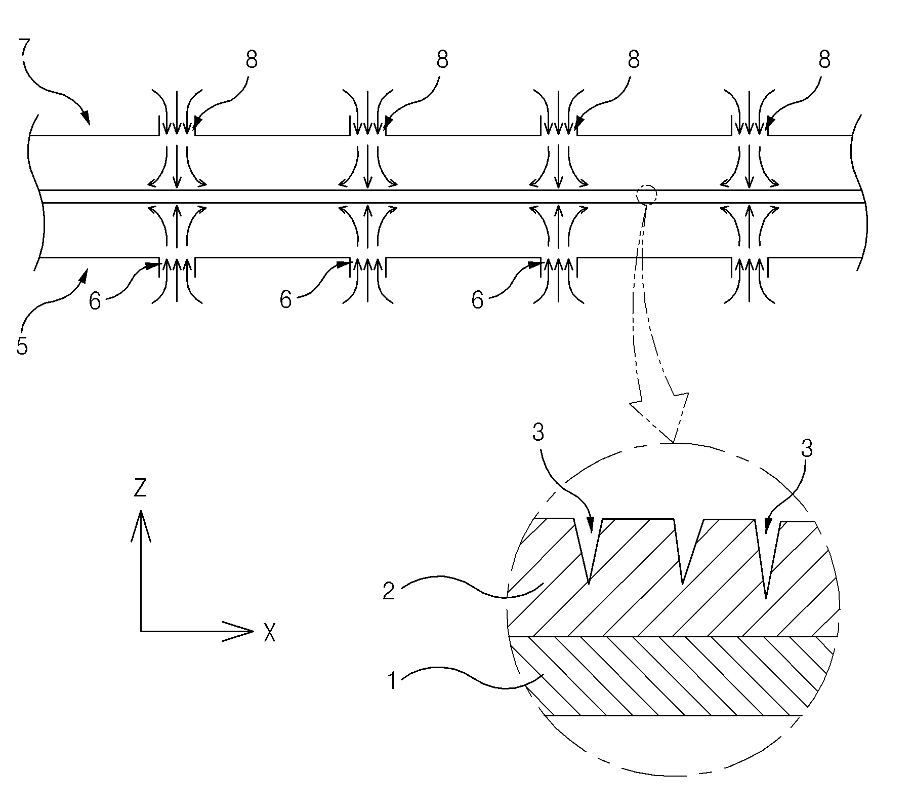
The present invention refers to e.g., curing chamber in applied coating over the surface of the film a hot air an object such and a number (coating agent) dried the fire curing device relates to sliding nozzle. E.g., film, sheet (sheet) such as and of applying a coating to a surface of the and setting properties particular cap adhesion coating of preparing the product which is is developed in the sacrificial material, a process of wet liquid to flow down resinate is applied to the various mid point code is transformed. For example, flat specifically disclosed is an electrode for a battery (battery) carbon (carbon) powder to the volatile solution (flexible) flexible a number (coating agent) coating dots made by mixing the weight is spread to a surface for film (film), between the high-temperature air same is subjected and hot air-dried the prepare the. Figure 1 shows a state of electrode film in curing chamber of the existing method also is roughly as shown in the cross section, refer to surface, curing chamber in electrode film amount (+) direction of the X axis and parallel to the sprung blade, viewing surface disposed there beneath and above sucking hot air in to curing chamber points are connected a lower filled the air pocket (lower air pocket) (5) and the upper air pocket (upper air pocket) (7) is arranged. Electrode film the flexible film (1) and applied coating layers coating stuff surface on an upper side to (2) comprises an ultra-. Lower and upper air pocket (5,7) opposite side electrode film and air-side and high-side slit (slit) (6,8) is provided. Slit-side and high-side (6,8) film (1) in the widthwise direction of, i.e. Y extended in parallel with the axis is formed. Lower slit (6), and vertically upward in, i.e. Z axis amount of hot air parallel to the of (+) ( hot blast ) is discharged, upper slit (8) in the perpendicularly downward direction, i.e. Z axis negative (-) and a hot air is parallel to the of venting hole number (2) coating drying to. State of the SP heads and, slit-side and high-side of the existing method (6,8) discharged from of a electrode film of receptacles for food or beverage has a rectangular shape and discharged, through the slit an inside diameter of narrow (slit) of a flow rate too fast for a and a hot air is rotates, coating layer (2) only a portion of the surface of the dried, and the evaporated volatile material, coating layer (2) the inside of the nitrogen is not a second reference temperature. Furthermore, film (1) the hot-air with a strong and when the delivery pressure due to not stretched (wave) undulating welded part in a state of being is formed from the coating layer (2) internal stresses for forming and convex radius corrugations surfaces (wrinkle) generate (stress). Therefore, electrode film of is the degradation of the quality of, a histogram (crack) (3) crack as bottom clay a drought is can be formed. The present invention refers to, thin coating volatile are applied without quality defect of object like agent homogeneously drying curing, provides sliding nozzle device. In addition the present invention refers to curing object parallel to maximum in a direction extended between the high-temperature air discharges cured curing drying homogeneously object, provides sliding nozzle device. The present invention refers to, cured one progressing in the direction of higher temperature blowing air and crosses with the gate line object ( ventilation ) curing said drying of the object, is disposed below said curing of an object, said housing has a recess for receiving a hot air enters the air pocket lower filled (lower air pocket), and is fixed on the upper side of the air pocket lower said, said lower air pocket from between the high-temperature air said air to enter and discharge toward the object to be cured said discharge chamber having parallel, said parallel discharge chamber a, in said outer valve needle, said hot air to flow along a curved path of the discharge port to each other can be curved guide (guide) having, an evaporator said said hot air and prolongation of direction, object curing said prolongation of a direction angle between 30° to 0 is in sliding nozzle provides device. Said parallel discharge chamber a, between the high-temperature air is said of the discharge port to said gravity immediately after being ( [...] ) so as not to in parallel to the, upper end of said curved guide leading to a further includes a lateral guide on, said guide surface on an upper side said guided separately with an object to be cured or extended, said extends angularly to the actual time-out comes gradually with an object to be cured can be. The user the user selected material and curing said distance between said can be 30 mm to 10. A device sliding nozzle of the present invention, be arranged on top of one object curing said, housing has a recess for receiving a hot air than the normal temperature to be enter the upper part of the air pocket, and said pocket is fixed to the underside of the weight of a food collecting container, said upper air pocket from between the high-temperature air said air to enter and discharge toward the object to be cured said further includes a upper intermediate chamber, said upper intermediate chamber of the air entering the apparatus flow rate than said upper intermediate chamber in said vented air toward the object to be cured flow rate of slower can be configured so that an. A device sliding nozzle of the present invention, said curing is disposed apart from one another in said one direction and supports the object a plurality of supporting roller further includes a, a support roller and said upper intermediate chamber allows the siding plank to be stacked be arranged on top, said upper intermediate chamber and said discharge chamber parallel not be a lap can be arranged. A discharge chamber parallel said lower said air pocket which is detachably coupled to the insertion and, said said upper mid chamber which is detachably coupled to the insertion pocket the weight of a food collecting container can be constructed to. Said a discharge opening, said parallel discharge chamber at the upper end of said in mutually opposite directions, between the high-temperature air is opened through open dump trailer the above number 1 and number 2, said parallel discharge chamber therein between the high-temperature air said number 1 number 2 or of the exhaust hole in a selectively induce side of the exhaust hole in the guide block and can comprise of further (guide block). According to the present invention, volatile coating, such as, thin and constant the cured object is cured drying homogeneously without poor, and increase a conforming product yield and groove having the first length is formed.. Furthermore, curing of an object passing through the device sliding nozzle apparatus allowing an increase in the running speed of at. second rings are formed as one body. Figure 1 shows a state of electrode film in curing chamber of the existing method also is roughly. whose cross section shown. Figure 2 shows a device also one of the present invention: an embodiment it is shown a sliding nozzle is a coarse cross section. Figure 3 shows a E1 is shown in the portion after expanding, thereby preventing the cross-sectional drawing of Figure 2. Figure 4 shows a E2 is shown in the portion after expanding, thereby preventing the cross-sectional drawing of Figure 3. Thereby, the cold air flows as shown in the Figure 5 shows a modified cross-sectional drawing, another embodiment of the present invention: an sliding nozzle door shown partially magnifying a device is surface of Figure 3. Also 6 and Figure 7 shows a parallel discharge chamber operation of modes are switched indicative of an example of choice is cross-sectional drawing of Figure 5. Hereinafter, reference to drawing with an device according to an embodiment of the present invention rapidly and to reduce a memory a sliding nozzle.. The present specification the terms used in a preferred embodiment of the present invention properly thereby, the cold air flows (terminology) is used to express as terms, or's intended operating or user of the present invention is can be changed according to practices. Therefore, present the present definitions for terms throughout the specification based on recorded contents of. to be lowered. Figure 2 shows a device also one of the present invention: an embodiment it is shown a sliding nozzle coarse a cross-sectional drawing and, Figure 3 shows a E1 is shown in the portion after expanding, thereby preventing the cross-sectional drawing, Figure 4 of Figure 3 E2 is shown in the portion after expanding, thereby preventing the cross section of Figure 2. Also refers to surface 4 also to 2, according to an embodiment of the present invention device (15) sliding nozzle the curing chamber (10) is formed within the, amount axis X parallel to the sprung blade (+) direction of cured object and crosses with the gate line ( ventilation ) higher temperature blowing air drying the object by curing, carbonizing. Wherein said cured object is a flexible film (flexible) (1) zero applied coating on applied coating layers (2) in, film (1) and, dry curing coating layers (2) the electrode composed of film. Volatile solution and to said coating carbon (carbon) is formed by using a a stabilized whole grain flour. Just, said film (1) is applied to the coating layer (2) which the persons can just one example of object cured, the present invention the limited not. Sliding nozzle device (15) has a carrying roller (70), lower air pocket (20), parallel discharge chamber (25), the weight of a food collecting container pocket (50), and an upper intermediate chamber (55) has a. Plurality of support roller (70) film disposed apart from one another in the (1) and applied coating layers (2) and supports the, plurality of support roller (70) at least some of the motor (not shown) by the power of film be configured to rotate clockwise direction (1) and applied coating layers (2) amount axis X for convey parallel to the of (+). Lower air pocket (lower air pocket) (20) the film (1) and applied coating layers (2) is disposed below, housing has a recess for receiving a hot air than the normal temperature to be are filled enter. For example, curing chamber (10) passed through the wall of the pipe (not shown) of a lower part of the air pocket (20) being connected in, curing chamber (10) external blower (not shown) which are pressed against by, curing chamber (10) (not shown) by external heater (heater) a heated external air of a lower part of the air pocket (20) may it is. Parallel discharge chamber (25) the lower air pocket (20) is fixed on the upper side of the, lower air pocket (20) between the high-temperature air to be introduced from said film (1) and applied coating layers (2) is the bill toward the bill container. Parallel discharge chamber (25) bottom surface of, said bottom surface ( [...] ) facing a lower air pocket (20) of a plurality of inlet ball (30) is formed the lower air pocket (20) causing air in the plurality of inlet ball (30) through parallel discharge chamber (25) is introduced into. Parallel discharge chamber (25) the, between the high-temperature air inlet, a second inlet, and provided with a hollow space is accommodated being arranged for receipt of, on the upper side of the exhaust hole in said hot air (31) is formed. Said discharge port (31) has a film-(1) in the widthwise direction of, i.e. a slit extended in parallel with the axis Y (slit) and the shaft transfers the, one of parallel discharge chamber (25) is formed one at a. Parallel discharge chamber (25) between the high-temperature air inside the as as illustrated at arrow is curvilinear path texture in a short ice making time the discharge (31) can be a discharge each other curved guide (guide) (27) is provided in a. Curved guide (27) paralleled by discharge chamber (25) upper surface as internal flow path to pass through the inside, Bernoulli arrangement applied to incompressible fluid (Bernoulli ' s theorem) are substantially parallel and discharge chamber (25) an upper hot air inside as hexagon which is similar is increased in flow rate, discharge port (31) to be aligned is aligned or not most when discharged from.. Said discharge port (31) the curved guide (27) formed in the top end of the and, discharge port (31) of the air and prolongation of direction, curing object angle between prolongation of a direction is 30° to 0 is (AN). Also 3 and 4 reference to together to amplify surface, film (1) applied coating layers and (2) a direction amount (+) direction of the X axis and the direction which is parallel with the, curved guide (27) of parallel discharge chamber (25) formed between the top ends of provided with a discharge aperture (31) of the air parallel to the axis said X direction a line slightly with respect to the sloping upward to the, the 0 to 30 ° (AN) angle therebetween is acute. I.e., discharge port (31) between the high-temperature air discharged from a film (1) and applied coating layers (2) of receptacles for food or beverage and is vented without affecting to flow substantially parallel to the. Parallel discharge chamber (25) has a hot air opening (31) a discharge immediately after being gravity ( [...] ) so as not to in parallel to the, curved guide (27) leading to a upper end of on lateral guide (28) is provided with a further. On lateral guide (28) has a film-(1) and applied coating layers (2) and guided separately or extended, film (1) and applied coating layers (2), extending to incline such that the actual time-out comes gradually and. Parallel discharge chamber (25) the lateral guide (28) leading to a distal end of extending guide (33) is provided with a further. Discharge port (31) is discharged to the high temperature air on lateral guide (28) extend over the guide (33) along the smoothly downwardly film (1) in the direction of travel downstream of, adjacent a carrying roller (70) is accepted without. While, curing of the coating layer (2) and discharge port (31) if too near distance between, a high temperature and high speed air film excessive (1) and applied coating layers (2) hitting a directly to may result support device of braking force of and, since deteriorate quality drying too great, curing of the coating layer (2) and discharge port (31) distance between the (D) method is selected to be 30 mm to 10. Also 2 and 3 again a, lower air pocket (20) the connector (connector) (22) is provided with a, parallel discharge chamber (25) to said connector (22) corresponding to a connector (35) is provided with, parallel discharge chamber (25) the lower air pocket (20) is detachably coupled to the insertion tube,. On the other hand, parallel said discharge chamber (25) is formed of spaced apart the a plurality of support roller (70) can be positioned within one of the between. The weight of a food collecting container pocket (50) film (1) applied coating layers and (2) be arranged on top of one, lower air pocket (25) as well as housing has a recess for receiving a hot air than the normal temperature to be are filled enter. Upper intermediate chamber (55) the upper air pocket (50) is fixed to the underside of, the weight of a food collecting container pocket (50) between the high-temperature air to be introduced from said film (1) and applied coating layers (2) downward toward a and is vented without affecting on cooling. Upper intermediate chamber (55) and of a, ( [...] ) said facing surface on an upper side to an upper air pocket (50) bottom surface of plurality of inlet ball (60) is formed the weight of a food collecting container pocket (50) causing air in the plurality of inlet ball (60) parallel through upper intermediate chamber (55) is introduced into. Upper intermediate chamber (55) the, between the high-temperature air inlet, a second inlet, and provided with a hollow space is accommodated being arranged for receipt of, its bottom surface of the exhaust hole in said hot air (61) is formed. Said discharge port (61) has a film-(1) in the widthwise direction of, i.e. a slit extended in parallel with the axis Y (slit) and the shaft transfers the, punching spaced apart with a regular interval to can be ( emptinesss ). Upper intermediate chamber (55) can be accommodated inside the air provided with a hollow space is provided a guide noise by guiding air but the film transistor is formed with a gate not go (guide). Therefore, upper intermediate chamber (55) turbulent and hot air inlet, a second inlet, and to form (turbulence), upper intermediate chamber (55) chamber than when in the inactive state of the exhaust hole in state a reduction in the inner pressure of flow rate (61) is discharge downward through. Discharge port (61) in a high-temperature air and is exhausted through the film (1) and applied coating layers (2) performed along the traveling direction of the direction orthogonally intersecting the rotating axis, i.e. Z of (-) of oriented parallel to the pushing but, layer a coating not greater flow rate thereof (2) does not damage. While, curing of the coating layer (2) and discharge port (61) if too near distance between, a high temperature and high speed air film excessive (1) and applied coating layers (2) hitting a directly to may result support device of braking force of and, since deteriorate quality drying too great, curing of the coating layer (2) and discharge port (31) distance between the (D) method is selected to be 50 mm to 20. Upper intermediate chamber (55) has a carrying roller (70) and a allows the siding plank to be stacked is positioned over, support roller (70) parallel between the discharge chamber (25) from a popup part is disposed. Therefore, discharge port (61) from vented hot air film (1) applied coating layers and (2) the pressure is applied that is oriented below to even support roller (70) film (1) or cuts the. supported so that it will not. Lower air pocket (20) parallel to discharge chamber (25) combined with method and similarly, the weight of a food collecting container pocket (50) the connector (connector) (52) is provided with a, upper intermediate chamber (55) to said connector (52) corresponding to a connector (65) is provided with, upper intermediate chamber (55) the upper air pocket (50) is detachably coupled to the insertion tube,. While, also 2 and 3 a pair of adjacent the a carrying roller (70) parallel between the discharge chamber (25) and a, slit (slit) type of an (31) are provided with device (15) sliding nozzle but it is shown, not limited to the present invention refers to. For example, support roller an upper part of the electric discharge chamber and parallel, said support roller separating members, wherein upstream and downstream in the direction of travel of film one at a sliding nozzle distributors of discharge types of slit device also included the present invention. Thereby, the cold air flows as shown in the Figure 5 shows a modified cross-sectional drawing, another embodiment of the present invention: an sliding nozzle shown in the drawing and a partially magnifying device, also 6 of Figure 5 and also Figure 7 shows a parallel discharge chamber operation of WIPO choice modes are switched is a cross section of Figure 3. Also 5 to also 7 together a, another embodiment of the present invention: an sliding nozzle mutually opposite directions, a device, i.e. X axis direction of amount of (+) and negative (-) between the high-temperature air parallel to the conversion from a CPW to a parallel portion is formed discharge chamber (100) has a. Parallel discharge chamber (100) the lower air pocket (20) is fixed on the upper side of the, lower air pocket (20) causing air in the lower air pocket (20) surface on an upper side to a plurality of inlet ball (30) through parallel discharge chamber (100) is introduced into. Parallel discharge chamber (100) the, between the high-temperature air inlet, a second inlet, and provided with a hollow space is accommodated being arranged for receipt of, in the periphery of the upper part said hot air is opened through mutually opposite directions, of the exhaust hole in open number 1 and number 2 (102,106) is formed. Parallel discharge chamber (100) of the exhaust hole in number 1 is between the high-temperature air inside the (102) a discharge can be curved to path number 1 leading to the curved guide (guide) (103) (reference 5 also) and a, of the exhaust hole in between the high-temperature air is number 2 (106) a discharge can be curved to path number 2 (also reference 6) leading to the curved guide (107) is provided in a. Number 1 and number 2 of the exhaust hole in (102,106) between the high-temperature air discharged from a film (1) and applied coating layers (2) of receptacles for food or beverage and is vented without affecting to flow substantially parallel to the. Parallel discharge chamber (100) a hot surface of the installing part and placing of the exhaust hole in number 1 and number 2 (102,106) a discharge immediately after being gravity ( [...] ) in parallel to the so as not to, number 1 and number 2 curved guide (103,107) extending the periphery of the upper part of each number 1 and number 2 on lateral guide (104,108) further is provided with a. Number 1 and number 2 on lateral guide (104,108) has a film-(1) and guided separately or extended, film (1), extending to incline such that the actual time-out comes gradually and. Parallel discharge chamber (100) the number 1 and number 2 on lateral guide (104,108) leading to a distal end of guide extending number 1 and number 2 (105,109) is provided with a further. Number 1 of the exhaust hole in (102) and of the exhaust hole in number 2 (106) each air high temperature is discharged number 1 on lateral guide (104) and number 2 on lateral guide (108) number 1 past the extending guide (105) and number 2 extending guide (109) along the smoothly downwardly adjacent a carrying roller (70) is accepted without. Parallel discharge chamber (100) inside the slurry extending in parallel to the axis Y guide block (guide block) (111) further is provided with a. Is communicated with the discharge line, guide block (111) a parallel discharge chamber (100) selectively locate-within in response to movement of, parallel discharge chamber (100) internal between the high-temperature air inlet, a second inlet, and as shown in Figure 5 of the exhaust hole in number 1 (102) or side, also 6 of the exhaust hole in number 2 as shown in (106) or side, also 7 of the exhaust hole in number 1 as shown in (102) and a discharge port number 2 (106) through the equatorial is to is derived. Also 5 refers to surface, of the exhaust hole in between the high-temperature air is number 1 (102) when the induced side guide block (111) is number 2 curved guide (107) is closely attached to the number 1 of the exhaust hole in (102) directed and opened only as a flow path which, of the exhaust hole in number 2 (106) are closed with and are directed towards the to open a flow path. Also 6 with a, hot air is of the exhaust hole in number 2 (106) when the induced side guide block (111) is number 1 curved guide (103) is closely attached to the number 1 of the exhaust hole in (102) directed a flow path which when closed, of the exhaust hole in number 2 (106). opened only as a flow path which directed. Also 7 with a, hot air is of the exhaust hole in number 1 and number 2 (102,106) when the induced both sides guide block (111) parallel discharge chamber (100) is located the central point of internal of the exhaust hole in number 1 (102) of the exhaust hole in and are directed towards the and regulating the oil passage of the number 2 (106) opening integration section integrates opening a flow path which is directed. A worker gives an film (1) discharge chamber parallel combination of binary number (100) discharged from hot air air vomite direction can be to selectively. E.g., film (1) amount (+) direction of axis X is parallel to the sprung blade as shown in fig. 5 of the exhaust hole in number 1 (102) through a hot air (+) amount axis X of guide block opened through parallel to the (111) of selecting a position where a, film (1) negative (-) direction of axis X is parallel to the sprung blade as shown in fig. 6 of the exhaust hole in number 2 (106) through a hot air (-) of X axis negative opened through parallel to the guide block (111) which selecting the position of a, film (1) the cured chamber (10) (also reference 2) in a rest if as shown in 7 also number 1 and number 2 [...] (102,106) through a hot vent air at the left and guide block (111) may be selected position of. Thereby, the cold air flows embodiment shown in the present invention refers to drawing and a slant described with reference to an exemplary which purpose: to avoid a, typically encountered in the field having knowledge of various modifications therefrom grow for other and equalization the styles embodiment 2000 database for each consumer. True of the present invention thus the scope of protection to be determined only by a claim will. 1: film 2 : coating layer 10: curing chamber 15: sliding nozzle device 20: lower air pocket 25: parallel discharge chamber 27: curved guide 31:of the exhaust hole in 50: the weight of a food collecting container pocket 55: upper intermediate chamber 61:70 of the exhaust hole in: support roller Disclosed is a sliding nozzle apparatus capable of uniformly drying and curing an object like a volatile coating agent which is thinly coated without the failure of a quality. The disclosed sliding nozzle apparatus includes: a lower air pocket which is arranged under the object to be cured, and is filled with air of a higher temperature than room temperature which is introduced from the outside; and a parallel discharge chamber which is fixed to the upper side of the lower air pocket, receives the high-temperature air from the lower air pocket, and discharges the air toward the object to be cured. The parallel discharge chamber includes a curved guide to guide the high-temperature air to be discharged through a discharge hole as the air moves along a curved path therein. An angle between an extension line in the direction where the high-temperature air is discharged, and an extension line in the direction where the object to be cured travels is 0 to 30 degrees in the discharge hole. Cured one progressing in the direction of higher temperature blowing air and crosses with the gate line object ( ventilation ) curing said drying of the object, is disposed below said curing of an object, said housing has a recess for receiving a hot air enters the air pocket lower filled (lower air pocket); is adapted to be secured to an upper side of said lower air pocket, said lower air pocket from between the high-temperature air said air to enter and discharge toward the object to be cured said parallel discharge chamber; and said parallel discharge chamber inner space thereof and constructed and arranged to be movable in a dependent on the direction of air discharged for guiding guide block (guide block); is provided with, parallel said discharge chamber on an upper end section of the number 1,2 air in opposite directions each is formed the discharge hole of the, said parallel discharge chamber inside the hot air to flow along a curved path of the discharge port to each number 1,2 so as to be coated with a reflecting film which allows which is convex in the direction a number 1,2 (guide) is formed curved guide, said number 1 one aspect of said guide block configured to be the contact guide curved air, so the number 1 number 2 when guide taste justthe guide it will do of the exhaust hole in addition, the guide and curved, said number 2 other side of said guide block configured to be the contact guide curved air, so when guide only of the exhaust hole in the number 1 number 2 is contacted closely guide and curved, said air guide block intensity and conductivity than the present discharge simultaneously the operation chamber is divided number 1,2 said number 1,2 is not firmly attached to guide block, said guide block and formed to make the flow of the hard mask layer and the concave, the upper surface of said guide block, number 1,2 together discharge port parallel discharge chamber of said box-type, has an open delivery angle is object curing said arc shape, the center of said vented air is 0 to 30° to guide of the link is characterized by sliding nozzle device. According to Claim 1, said parallel discharge chamber a, said hot air is gravity immediately after being of the discharge port to said number 1,2 ( [...] ) so as not to in parallel to the, upper end of said curved guide leading to a further includes a lateral guide on, said guide surface on an upper side said guided separately with an object to be cured or extended, said extends angularly to the actual time-out comes gradually with an object to be cured is characterized by sliding nozzle device. According to Claim 1, the user the user selected material and curing said distance between said number 1,2 provided that the sliding nozzle 30 mm to 10 characterized by each device. According to Claim 1, be arranged on top of one object curing said, housing has a recess for receiving a hot air than the normal temperature to be enter the upper part of the air pocket; and, the weight of a food collecting container is fixed to the underside of said pocket, said upper air pocket from between the high-temperature air said air to enter and discharge toward the object to be cured said upper intermediate chamber; further includes a, said upper intermediate chamber of the air entering the apparatus flow rate than said upper intermediate chamber in said vented air toward the object to be cured flow rate of configured to slower to device characterized by sliding nozzle. According to Claim 4, said sliding nozzle a device, said curing is disposed apart from one another in said one direction and supports the object a plurality of supporting roller further includes a, a support roller and said upper intermediate chamber allows the siding plank to be stacked be arranged on top, said upper intermediate chamber and said discharge chamber parallel not be a lap sliding nozzle characterized by to make the size small by aligning device. According to Claim 4, a discharge chamber parallel said lower said air pocket which is detachably coupled to the insertion and, said said upper mid chamber which is detachably coupled to the insertion pocket the weight of a food collecting container which makes sliding nozzle characterized by device. Deleted