유도가열 조리기기
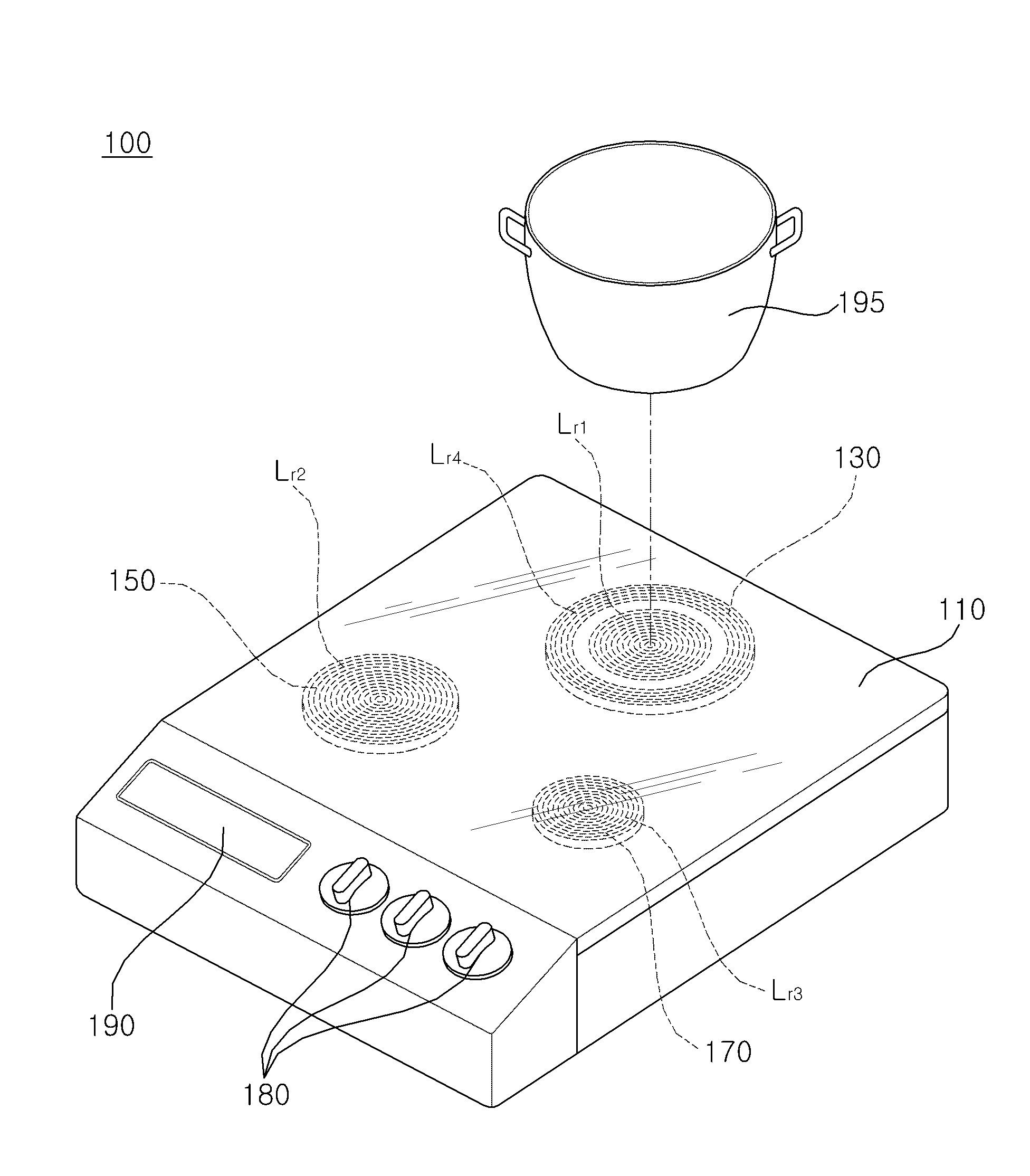
The present invention relates to induction heating cooking appliance and, more particularly an induction heating can be efficiently driven heaters are disclosed. The cooker, microwave electronic microwave oven (microwave oven), a structure for mounting handles oven (microwave oven), at least two kinds of preset temperature (cooktop) products frequently disclosed. The microwave generated by the magnetron microwave oven provided in the cooking chamber closed by irradiating heating of food by vibrating bound water contained in the food, the cooking chamber is sealed by using a heater oven includes a cooking chamber by heating provides compressed heated. On the other hand, mounted on the upper surface generally cook tower by heating it takes out the heating of the food substance contained in the, gas as a heat source in a representative gas cook tower are disclosed. When gas units belongs, from the inner surface of a flame by the cursor heat loss by electricity permits in cook tower cookies etc.. The aim of the invention, induction heating coils operating efficiently driven switching device providing an induction heating cooker 4 to 5. It is another object of the present invention, effectively without reducing power that can drive an induction heating cooking machinery and tools provided 4 to 5. Also, it is another object of the present invention, heat loss may perform an operation on a stable high frequency heating cooking appliance 4 to 5. Order to achieve this object according to an embodiment of the present invention for the induction heating cooker, and inverter switching elements, by the operation of the switching element, inverter and DC power into AC power to be supplied, are heated by the AC power, and an induction heating coil 2 is installed to be connected in parallel with each other and side wall 1, 1 and 2 respectively connect to the first induction heating coil induction heating coil switching element and second switching element switching inverter 2 with 1, 1 and 2 switching at least one of the first switching element turning on or turn off, inverter switching for forming gate signal is disabled. According to an embodiment of the present invention, operating the switching element forming the zero voltage switching in which an induction heating coil, electrically efficiency is equal to or higher. In particular, reducing the loss of power switching and is, further increase the life of the circuit element is equal to or higher. On the other hand, a plurality of induction heating coil connected in parallel with one of at least 2 simultaneously when heated by the induction heating coil, each induction heating coil an AC power supplied from the inverter to supply different, without reducing power, efficiently or stable induction heating cooker directly is equal to or higher. On the other hand, utilizes heating plate under the heating section, flame being free, the pin is certain sizes of stability. Also, the heating section, in particular, not direct heating by the induction heating coil, a high-frequency current supply continuously is used, a high energy efficiency and heating time is saved tranfectants disclosed. Figure 1 shows a dB rotor induction heating cooking in accordance with one embodiment there are disclosed. Figure 2 shows a also induction heating cooker the internal block of one example of the matrix. Figure 4 shows a 3 also to describe the operation of the induction heating cooker of Figure 2 also referenced are disclosed. Figure 5 shows a also the internal block of the induction heating cooker of Figure 1 one example of the matrix. Figure 6 shows a induction heating cooker the internal block of another example of a of Figure 1 also are disclosed. Figure 7 shows a heating unit of Figure 5 of Figure 1 showing the placement of the induction heating coil also are disclosed. Is less than the HTML page which utilizes the present invention more specifically described as follows. "Module" and "part" components which are used in the description below for suffix is simply the ease of specification writing into consideration given only provided, itself is specially important meanings or serves not the imparting antistatic property. The, the "module" and "part" used in mixed each other may be filled. Figure 1 shows a dB rotor induction heating cooking in accordance with one embodiment there are disclosed. The reference also 1, one embodiment of the invention inductive heating cooker (100) is, heating plate (110), a first heating section 1 (130), a first heating section 2 (150), a first heating section 3 (170), an operation unit (180), and the display unit (190) can be a. Heating plate (110) includes induction heating cooker (100) as the casing, is arranged on the each color. Heating plate (110) is, ceramic, glass material such as implemented in disclosed. Heating plate (110) on top of cooking vessel is situated, in particular cooking vessel (195) is carry each color (130,150,170) that when disposed on at least one of the, heated by induction heating principle to be coated. 1 first heating section (130) is, a resonant capacitor (not shown) and a plurality of induction heating coil with each other. In the drawing, the first induction heating coil (Lr1) 1 and induction heating coil (Lr4) which is exemplified with a 4, 4 1 (Lr4) one of the first induction heating coil disposed about the periphery of the first induction heating coil (Lr1) exemplified as follows. In addition, induction heating coil 1 and second induction heating coil 2 also pivotably disposed parallel or the like. Cooking vessel (195) 1 first heating section (130), particularly a 1 (Lr1) increase on the induction heating coil, the first induction heating coil (Lr1) 1 alternating current, an alternating current of parasitic capacitance is electrically connected, a resonant capacitor (not shown) and second induction heating coil 1 (Lr1) by through terminals, generating a first induction heating coil (Lr1) 1 ferromagnetic, electromagnetic induction by a magnetic field due to the, cooking vessel (195) derived to eddy current (Eddy current) to be coated. (Joul) cooking vessel by an eddy current resistance of Joule heat food uniformly by vessel is heatable in components to be coated. On the other hand, in addition to the first induction heating coil (Lr1) 1, 4 even cooking vessel on the first induction heating coil (Lr4) (195) if units, first induction heating coil (Lr1) 1 and 4 is connected to a high frequency induction heating coil (Lr4) both alternating current, as by an eddy current above, cooking vessel (195) to be coated is heated. 2 first heating section (150) is, 2 (Lr2) first induction heating coil (not shown) and a resonant capacitor contact with each other. Cooking vessel (195) 2 first heating section (150), in particular on the first induction heating coil 2 (Lr2) increase, high frequency AC current is electrically connected, as by an eddy current described above, cooking vessel (195) to be coated is heated. 3 first heating section (170) is, first induction heating coil 3 (Lr3) (not shown) and a resonant capacitor contact with each other. Cooking vessel (195) 3 first heating section (170), in particular on the first induction heating coil 3 (Lr3) increase, high frequency AC current is electrically connected, as by an eddy current described above, cooking vessel (195) to be coated is heated. An operation unit (180) is, according to the manipulation by the user, induction heating cooker (100) and n is an integer operation. For example, by an operation of a user, a first heating section 1 (130), a first heating section 2 (150), a first heating section 3 (170) whether at least one heating, or, 1 first heating section (130) and 1 in an induction heating coil (Lr1) 4 (Lr4) whether current is supplied to the induction heating coil to any of, or each of the heating section to select or operation time can be determined temperature selection. An operation unit (180) is such as drawing, each color (130,150,170) pivotably also supplies data signals. Display unit (190) is, induction heating cooker (100) of the overall operation of the state substrate. Each color (130,150,170) during is operated to determine whether, under heating cooker (195) temperature are indicated on the other. On the other hand, according to an embodiment of the present invention induction heating cooker (100) in addition, radiant heat (radiant heat) of the cooker, induction heating cooker (100) in the same manner as on, heating plate (110) utilizes under heating section, not flame, the pin is certain sizes of stability. However, the radiant heat in the water is heightened and forms a heating according, for the protection of the heating section, on/off control is necessary thereto. However, according to an embodiment of the present invention induction heating cooker (100) is, utilizes high frequency for induction heating by a principle, the heating section, in particular, not direct heating by the induction heating coil, a high-frequency current supply continuously and is used, heating time and high energy efficiency to reduce tranfectants disclosed. On the other hand, induction heating cooker (100) is, when induction heating cooker component since the non conduction plate, to supplement the same, i.e. non-magnetic for cooking vessel to perform even when heating, separate (not shown) can be further transferred to the heating section. Heat the heating section (not shown) is, each color (130,150,170) disposed at least one of disapproval. Otherwise, induction heating cooker (100) is, load detector (not shown) further include an outer for cooking vessel may be filled. Figure 2 shows a also induction heating cooker the internal block of one example of the matrix. HTML page through described, in one embodiment of the present invention induction heating cooker (200) is, converter (210), reactor (L), a smoothing capacitor (C), inverter (220), (S1 - S2) first switching element 1 first to 2, 1 to 2 second first induction heating coil (Lr1 - Lr1), 1 first resonant (Cr1 - Cr2) comprising the first to 2. On the other hand, control unit (not shown), the temperature (not shown), input current detector (not shown) can be further comprising. Converter (210) is, commercial AC power (205) receives, a DC power source and converts each of the outputs. For example, converter (210) is provided with a diode component, diode element is rectified DC power source can be a power outputs. On the other hand, converter (210) is, diode device and having a switching element, the switching operation of rectification of the converted DC power output and diode element according may be filled. Is less than the converter (210) comprising a diode element is a switching element that is not about described. On the other hand, commercial AC power (205) is single-phase AC power supply or can be a three-phase AC power. When a single-phase AC power supply, converter (210) is, bridge type diode element 4 as can be. When three-phase AC power supply, converter (210) is, 6 diode elements disapproval. Reactor (L) is, converter (210) each connected to one end of, the AC component of energy-accumulating, harmonic current component or removes noise components a plurality of hierarchies. (C) is a smoothing capacitor, converter (210) output-connected with each other. Drawing in capacitor converter (210) are disposed between the reactor (L) system is. (C) is a smoothing capacitor, converter (210) is equal to smooth the rectified power outputted from a DC power source. Is less than the converter (210) dc stage suitable for a response. Dc stage of smooth DC voltage inverter (220) applied. Inverter (220) is, sang-am (Sa) switching element connected each other in series with a switching element and a lash (S'a), on/off operation of the switching element by, smooth direct current power and a predetermined frequency AC power converter. Each switching element can be connected to a diode is reverse in line (Sa, S'a). Also, each switching element (Sa, S'a) is snubber capacitor can be connected respectively in parallel. Inverter (220) in the switching elements (Sa, S'a), based on the switching control signal from control unit (not shown), turn-on/turn-off operation to be coated. The, the switching elements (Sa, S'a), complementary each other operating disapproval. The first induction heating coil (Lr1) 1 2 (Lr2) first induction heating coil connected in parallel with each other a couple of substrate. On the other hand, induction heating coil (Lr1) respective first induction heating coil (Lr2) is 1 2, 1 2 (Cr2) respectively for the first resonant resonant resonance (Cr1) can be connected. Each induction heating coil (Lr1, Lr2) to a high frequency alternating power is supplied, the above-mentioned induction heating in accordance with the principles, to enable the heating can be. The, operation of the switching element (S1, S2) determining each induction heating coil (Lr1, Lr2) 1 is respectively connected to the first induction heating coil (Lr1) induction heating coil 2 (Lr2) can be. On the other hand, control unit (not shown) is, inverter (220) in the switching element (Sa. S'a), 2 (S1 - S2) for operation of each induction heating coil can be first to control the operation of the first switching element 1. In particular, inverter (220) to control, pulse width modulation (PWm) cooking mode switching control signal can be output. Inverter (220) when the element is in IGBT (Insulated gate bipolar transistor), pulse width modulation (PWm) type gate oxide film can output a driving control signal. On the other hand, control unit (not shown) is, in the vicinity of each induction heating coil (not shown) for sensing a temperature of the temperature on, input current from the AC power supply (not shown) input current detector detecting from commercial, an output value of the respective, strange induction heating cooker (100) whole from a power may be filled. Figure 4 shows a 3 also to describe the operation of the induction heating cooker of Figure 2 also referenced are disclosed. Of Figure 2 induction heating cooker (200) is, one inverter (220) connected in parallel by using a plurality of induction heating coil (Lr1, Lr2), increasing energy efficiency to be coated. In particular, one of the switches the heating coil, maximum output if necessary, all the operation of the induction heating coil (Lr1, Lr2) to be coated. I.e., 1 to 2 second (S1, S2) are turned on to a second switching element are disclosed. Figure 3, during predetermined cycle (T), during the first period (T1) 1 1 (S1) (S2) (on) that a first switching element switching element 2 and, thereafter, the second switching element 2 (S2) is in an off state (off) to exemplify the each other. The, 1 period (T1) and second induction heating coil 1 and second induction heating coil (Lr2) 2 (Lr1) operating switches, 2 second period (T2) operating only during induction heating coil (Lr1) is equal to 1. On the other hand, when (turn off) 2 (S2) of the first switching element is turned off, the power supply supplies electric energy to execute the switching operation, reducing the loss of power switching and is, further increase the life of the circuit element is equal to or higher. To this end, in an embodiment of the present invention, the first switching element 1 (S1) or (S2) 2 switching element turned on turning on or off, power supply supplies, to electric energy, inverter in the inverter operation of the switching element to control. Figure 4 example same as follows. Figure 4, during predetermined cycle (T), 1 (S1) or (S2) is turned first switching element turning on or off a switching element 2 AC (220) gate signal is disabled (disable) in inverter switching element (Sa or S'a) melt viscosity of 0.1 is exemplified substrate. In with thingsang-am inverter switching element is less than the switching element (Sa) is described. First, during the first period (T1) 1 1 (S1) (S2) turning on the first switching element simultaneously when switching element 2 (on), control unit (not shown) is, sang-am (Si) gate driving signal applied to the switching element (Sa) momentarily disabled (disable) oxide layer. The switching power supply supplies to be coated. The, first switching element 1 (S1) (S2) 2 auto first switching element turned on, is equal to the power consumption is reduced. On the other hand, gate driving signal line (Si) dead time (dead time) period or more sang-am period be a switching element. In the drawing, period T1a exemplified as follows. Next, disable period after, gate driving signal (Si) enable (enable) is switched to the other. 1 (S1) and (S2) 2 first switching element holds the switching element is on (on) state. The, first induction heating coil (Lr1) 1 and 2 is equal to the induction heating coil (Lr2) is operated. Next, just before turn-off of the first switching element 2 (S2), gate driving signal (Si) is again disabled (disable) is switched to the other. On the other hand, gate driving signal line (Si) dead time (dead time) period or more sang-am period be a switching element. In the drawing, period T1b exemplified as follows. Next, the first switching element is turned on and off 2 (S2), after period T2a, gate driving signal (Si) is again enabled (enable) is switched to the other. 2 (S2) turn off the first switching element, the switching power supply supplies, power consumption is reduced to the TFTs. 1 (S1) holds the first switching element is on (on) state. The, operating only the first induction heating coil (Lr1) is equal to 1. Next, just before turn-off of the first switching element 1 (S1), gate driving signal (Si) is again disabled (disable) is switched to the other. On the other hand, gate driving signal line (Si) dead time (dead time) period or more sang-am period be a switching element. In the drawing, T2b period exemplified as follows. As described above, each switching element (S1 or S2) turn on and off, temporarily inverter (220) are kept disabled and thus in switching element driving signal, a flyback converter is capable of operation corresponding switching element, the switching unit is equal to or higher. Further for formed on the equal to be. Figure 5 shows a also the internal block of the induction heating cooker of Figure 1 one example of the matrix. HTML page through described, in one embodiment of the present invention induction heating cooker (500) is, first 1 converter (510), the first 2 converter (515), first reactor 1 (L1), (L2) first reactor 2, a smoothing capacitor (C1) first 1, second 2 of a smoothing capacitor (C2), the first inverter 1 (520), the first inverter 2 (525), power selection unit (530), first switching element 1 (S1 - S4) first to 4, 1 to 4 first first induction heating coil (Lr1 - Lr4), 1 to 4 comprising the first first resonant (Cr1 - Cr4). On the other hand, control unit (not shown), the temperature (not shown), input current detector (not shown) can be further comprising. Of Figure 5 induction heating cooker (500) is, of Figure 2 induction heating cooker (200) relative to, a plurality of converter (510,515), plurality of inverters (520,525), a plurality of reactor (L1, L2), and a plurality of smooth capacitor (C1, C2) with each other or the like. The account of the 2 also refers to omit other. On the other hand, 1 first inverter (520) and the second inverter 2 (525) of operation can be performed separately. I.e., 1 and 2 respectively can be creates and outputs a high frequency AC power to high frequency AC power. The first induction heating coil (Lr1) 1 2 (Lr2) first induction heating coil connected in parallel with each other a couple of substrate. On the other hand, induction heating coil (Lr1) respective first induction heating coil (Lr2) is 1 2, 1 2 (Cr2) respectively for the first resonant resonant resonance (Cr1) can be connected. Each induction heating coil (Lr1, Lr2) to a high frequency alternating power is supplied, the above-mentioned induction heating in accordance with the principles, to enable the heating can be. The, operation of the switching element (S1, S2) determining each induction heating coil (Lr1, Lr2) 1 is respectively connected to the first induction heating coil (Lr1) induction heating coil 2 (Lr2) can be. The first induction heating coil (Lr3) 4 3 first induction heating coil (Lr4) connected in parallel with each other a couple of substrate. On the other hand, induction heating coil 3 (Lr3) respective first induction heating coil 4 is (Lr4), respectively for the first resonant resonant (Cr3) 3 4 (Cr4) resonance can be connected. Each induction heating coil (Lr3, Lr4) high frequency AC power is supplied, the above-mentioned induction heating in accordance with the principles, to enable the heating can be. The, each induction heating coil (Lr3, Lr4) (S3, S4) determining operation of the switching element 3 is respectively connected to the first induction heating coil (Lr3) induction heating coil 4 (Lr4) can be. On the other hand, operation of the first switching element (S1 - S4) first to 4 1, as above-mentioned, a flyback converter can be performed. I.e., at least one of the first switching element 1 (S1 - S4) first to 4 when turning on or turned off, control unit (not shown) is, inverter (520,525) momentarily disabled (disable) (Si) in gate driving signal applied to the base. The, operating the switching device is equal to the power consumption is reduced. In particular, carry power selection unit (530) operating in conjunction with a, each switching as to AC power when determined, corresponding alternating current power supply momentarily disabled (disable) inverter gate driving signal (Si) can be up. Power selection unit (530) is, first induction heating coil (Lr1) 1 and 2 and a second handle when operated both induction heating coil (Lr2) 1 inverter (520) 1 and 2 from first AC power inverter (525) 2 1 selects a second one of the first AC power from AC power, and be supplied to the first induction heating coil (Lr1) 1, 2 AC power to be supplied to the first induction heating coil (Lr2) selecting first 2 controls pressure. For example, the first induction heating coil (Lr1) is provided with a 1st 1 controls to reduce the alternating current power supply 1, 2 is provided with a 1st first induction heating coil 2 (Lr2) can be controlled to alternating current power supply. The, at least one inverter connected in parallel to the same plurality of induction heating coil which is turned on when being at least 2, each separate AC power applied to the induction heating coil is equal to or higher. I.e., one from the different AC power supplied from an inverter is equal to or higher. The, same extending from the alternating current power supply disappears from lowering the inverter power reduction, each stably supplied AC power is equal to or higher. On the other hand, power selection unit (530) is, first induction heating coil (Lr3) 3 and 4 and a second handle when operated both induction heating coil (Lr4) 1 inverter (520) 1 and 2 from first AC power inverter (525) 2 2 selects a second one of the first AC power from an AC power supply, and be supplied to the first induction heating coil (Lr3) 3, 1 AC power to be supplied to the first induction heating coil (Lr4) 4 first selected with the curb. For example, induction heating coil (Lr3) controls to reduce the alternating current power supply 2 is provided with a 1st first 3, 4 1 is provided with a 1st first induction heating coil (Lr4) can be controlled to alternating current power supply. To this end power selection unit (530) is, relay element can be. 1 (R1) (R2) in drawing first connection to the first relay element 2 relay element is exemplified substrate. 1 relay element (R1) is first, inverter (520,225) 2 (Lr2) first induction heating coil arranged between, the first induction heating coil (Lr2) 1 2 second inverter (520) and the second inverter 2 (525) to be plugged into either relay operating on a chuck. 2 relay element (R2) is first, inverter (520,225) 4 (Lr4) first induction heating coil arranged between, the first induction heating coil (Lr4) 1 4 second inverter (520) and the second inverter 2 (525) to be plugged into either relay operating on a chuck. On the other hand, 1 (R1) (R2) of first relay operating a control of the first relay element 2 relay element, a control unit (not shown) can be performed by control signals. Figure 6 shows a induction heating cooker the internal block of another example of a of Figure 1 also are disclosed. HTML page through described, in one embodiment of the present invention induction heating cooker (600) is, of Figure 5 induction heating cooker (500) substantially the same disclosed. Differences less than the sub-only described. Of Figure 6 induction heating cooker (600) is, of Figure 5 induction heating cooker (500) on unlike, one dc employing a difference in that flow tides. I.e., 1 second inverter (620) and a second inverter 2 (625) is, one converter (610), reactor (L), a smoothing capacitor (C) share a. Otherwise, power selection unit (630), first (S1 - S4) first switching element 1 to 4, 1 to 4 first first induction heating coil (Lr1 - Lr4), 1 to 4 comprising the first first resonant (Cr1 - Cr4). On the other hand, control unit (not shown), the temperature (not shown), input current detector (not shown) can be further comprising. But employing a single dc, separate inverter (620,325) by using, as above-mentioned, power selection unit (630) is, first induction heating coil (Lr1) 1 and 2 and a second handle when operated both induction heating coil (Lr2) 1 inverter (620) 1 and 2 from first AC power inverter (625) to select one from either first 2 AC, and be supplied to the first induction heating coil (Lr1) 1, 2 the other first induction heating coil (Lr2) can be supplied to control. Also, power selection unit (630) is, first induction heating coil (Lr3) 3 and 4 and a second handle when operated both induction heating coil (Lr4) 1 inverter (620) 1 and 2 from first AC power inverter (625) selects one of the first AC power from 2, 3 and be supplied to the first induction heating coil (Lr3), 4 the other first induction heating coil (Lr4) can be supplied to control. The, operating power reduction from lowering even when a plurality of induction heating coil, each stably supplied AC power is equal to or higher. On the other hand, operation of the first switching element (S1 - S4) first to 4 1, as above-mentioned, a flyback converter can be performed. I.e., at least one of the first switching element 1 (S1 - S4) first to 4 when turning on or turned off, control unit (not shown) is, inverter (620,625) momentarily disabled (disable) (Si) in gate driving signal applied to the base. The, operating the switching device is equal to the power consumption is reduced. Figure 7 shows a heating unit of Figure 5 of Figure 1 showing the placement of the induction heating coil also are disclosed. The reference also 7, 1 first heating section (130) is, first induction heating coil (Lr1) 1 4 and induction heating coil (Lr4) with each other. And, first heating section 2 (150) is, induction heating coil 2 (Lr2) having first, second heating section 3 (170) is, first induction heating coil (Lr3) 3 with each other. 1 first heating section (130) 4 in an induction heating coil (Lr4) is, preferably disposed about the periphery of the first induction heating coil (Lr1) 1. 1 first heating section (130) is, with 2 of the induction heating coil, other heating section (150,170) is equal to or greater than the power heating cooking vessel. For example, equal to or higher than approximately 2 times the power heating cooking vessel. Such as placement also 7, 1 first heating section (130) only when operating in an induction heating coil (Lr1) 1, 1 (S1) and on is turned only first switching element. The, first induction heating coil (Lr1) 1 1 is stationary second inverter (520) (i1) 1 AC power supplied from the first. On the other hand, when working first induction heating coil (Lr4) 4, 4 (S4) first switching element is also turned on, tunable 4 1 is provided with a 1st first induction heating coil (Lr4) unlike the first induction heating coil (Lr1) 2 inverter (525) 2 AC power from the two first (i2), power selection unit (530) 2 (R2) has a relay element 2 in an inverter (525) connect to the relay operation is carried out. On the other hand, 2 2 first heating section in an induction heating coil (Lr2) which operate, when first heating section in an induction heating coil (Lr1) 1 1 operate, the first switching element is turned on and a first switching element 1 (S1) 2 (S2) and on. The, first induction heating coil (Lr1) 1 1 is stationary second inverter (520) (i1) 1 AC power supplied from the first. On the other hand, tunable 2 2 is provided with a 1st first induction heating coil (Lr2) inverter (525) 2 AC power from the two first (i2), power selection unit (530) (R1) 2 has a relay element 1 in an inverter (525) connect to the relay operation is carried out. On the other hand, the operation of the first heating section in an induction heating coil (Lr3) and 3 3, 1 1 when first heating section in an induction heating coil (Lr1) operates, each induction heating coil (Lr1, Lr3) since all is stationary, power selection unit (530) is independent of the operation of, 1 3 (S3) (S1) first switching element are turned on when the first switching element are disclosed. The, first induction heating coil (Lr1) 1 1 second inverter (520) (i1) 1 AC power supplied from the first, second induction heating coil (Lr3) 2 3 second inverter (520) 2 (i2) from AC power is first supplied. On the other hand, the operation of the first heating section in an induction heating coil (Lr3) and 3 3, 1 4 first heating section in an induction heating coil (Lr4) disapproval operate simultaneously. In this case, the first switching element is turned on and a first switching element (S3) 3 4 (S4) and on. The, first induction heating coil is stationary (Lr3) 2 3 second inverter (525) 2 (i2) supplied from the second AC power. On the other hand, induction heating coil 4 (Lr4) 1 is provided with a 1st first tunable inverter (520) 1 AC power from the two first (i1), power selection unit (530) 2 relay element (R2) has a 1 in an inverter (520) connect to the relay operation is carried out. On the other hand, when the induction heating coil (Lr1 - Lr4) all operate, (S1 - S4) all switching element is turned on and on. In this case, each inverter (520,525) is partitioned from each AC power supplied to the induction heating coil (Lr1 - Lr4) (i1, i2) each to be coated. The, power selection unit (530) 1 relay element (R1) has a 1 in an inverter (520) connect to the relay operation is being performed, 2 relay element (R2) 2 has a first inverter (525) can be connect to the relay operation. On the other hand, as described above, i.e., at least one of the first switching element 1 (S1 - S4) first to 4 when turning on or turned off, control unit (not shown) is, inverter (520,525) momentarily disabled (disable) (Si) in gate driving signal applied to the base. The, operating the switching device is equal to the power consumption is reduced. The configuration of the induction heating cooker as described embodiments but can be applied to defined and method, various modifications can be made to the embodiments all or a portion of a front end of the selectively combined each embodiments of the disapproval. On the other hand, the induction heating cooker processes an induction heating cooker processor readable recording medium is more than implementing a processor is readable code. Processor-readable recording medium which can be read by a processor where the data is stored includes all kinds of recording device. Also, in a preferred embodiment of the present invention but more series and described, the invention provides a correspondingly defined in one particular embodiment, the subject matter of the present invention claimed in the claims made without deviating from the invention in various embodiments is provided to 155.520 deformation thereby enabling as well as, in technical idea of the present invention modifications are or will be understood to must not separately from the outlook. PURPOSE: An inductive heating cooking device is provided to continuously supply a high frequency current to a heating unit, thereby shortening heating time and increasing energy efficiency. CONSTITUTION: An inverter(220) converts DC power into first AC power by an operation of a switching element. A first inductive heating coil(Lr1) and a second inductive heating coil(Lr2) are heated by the first AC power. A first switching element(S1) and a second switching element(S2) are switched to connect a first inductive heating coil and a second inductive heating coil to the inverter. A converter(210) converts commercial AC power(205) into DC power. A reactor(L) eliminates a high frequency current component or a noise component. And inverter switching elements, by the operation of the switching element, the inverter supplies the DC power into AC power 1 first; the 1 are heated by the AC power, induction heating coil 1 and induction heating coil 2 is installed to be connected in parallel with each other; and a second induction heating coil 1 and respectively connect to the induction heating coil 2 1 2 switching element and second switching element switching the inverter; with, 1 2 turning on the switching device and the switching at least one of turning on or off, the inverter switching element characterized in that the gate signal is disabled an induction heating cooker. According to Claim 1, 2 at least one of turning on the switching device and the switching element 1 after turning on or off, the inverter gate signal to a switching element characterized a which is [pul[pul] is an induction heating cooker. According to Claim 1, 1 2 turning on the switching device and the switching at least one of turning on or off, the inverter gate signal disabled at least dead time switching element characterized in an induction heating cooker. According to Claim 1, and inverter switching elements, by the operation of the switching element, the first 2 2 by inserting the first DC power into AC power inverter; the 2 are heated by the AC power, and induction heating coil 4 induction heating coil 3 is installed to be connected in parallel with each other; and a second induction heating coil 3 and 4 respectively connect to the first induction heating coil 3 and 4 switching element switching element switching the inverter 2; with, 3 4 turning on the switching device and the switching at least one of turning on or off, characterized in that the inverter switching for forming gate signal is disabled 2 an induction heating cooker. According to Claim 4, at least one of turning on the switching device and the switching element 3 4 after turning on or off, characterized in that the inverter switching for forming gate signal is an induction heating cooker a which is [pul[pul] is 2. According to Claim 4, 3 4 turning on the switching device and at least one of turning on or off the switching element, the switching element 2 inverter gate signal characterized at least dead time disabled an induction heating cooker. According to Claim 4, 1 4 with the induction heating coil and a second induction heating coil, the second induction heating coil disposed about the periphery of the induction heating coil 4 1 1 second heating section; 2 2 the induction heating coil having a first heating section; and a second induction heating coil having a first heating section 3 3; characterized in further including an induction heating cooker. According to Claim 4, the induction heating coil and a second induction heating coil when operated 1 2, 1 2 1 AC power to the AC power source and the first of the AC power supplied to the induction heating coil to select 1, 2 AC power to the first induction heating coil 2 may be supplied to power selection unit selects; characterized in further comprising an induction heating cooker. According to Claim 8, the power selector, the induction heating coil 3 and the second induction heating coil 4 when operated, the AC power source and the first AC power during AC power 1 2 2 3 selects the first induction heating coil and be supplied to, 1 AC power to the first induction heating coil 4 selects characterized be supplied to an induction heating cooker.