미세기포 발생용 기체용해장치를 포함한 고밀도 미세기포 발생장치
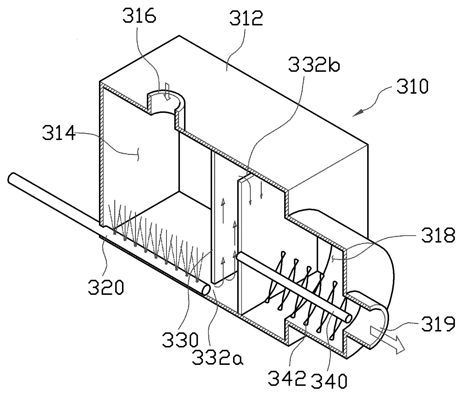
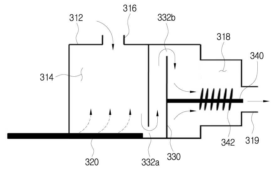
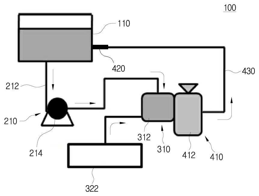
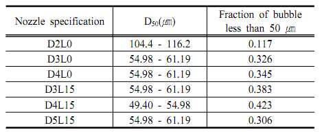
The present invention refers to a high-density micro-bubble generation device relates to pouring for gas dissolving device, more particularly micro-bubble generation device installed at the front end of dissolving gas pressure tank generally have low solubility gas or the like after a pressure tank to dissolve in the circulating water tank is mixed circulating water simultaneously discharged through the venturi nozzle by generating blisters in a passing of the emergent, high density fine bubble to more efficiently generate high density micro-bubble generation device including a pouring for gas dissolving device are disclosed. Generally, a large amount of oxygen is included in the middle water aquatic plants or animal can, if oxygen is insufficient in water, since water is a herbaceous, water can be contaminated. I.e., when large oxygen in water, is oxidizable by oxygen tank in water, which is decomposed process it into the water can be purified in the conductive aerobic clean air oxygen saturated dissolved oxygen in water under the same conditions for covering pipes is the timing relay in large amounts of contaminants and the purification produce difficult anaerobic state is lengthened by the vehicle from the outside. The, quantity of dissolved oxygen in water contained in a duct of oxygen such as ozone water is high (hydrogen peroxide) also serving as the center of gravity of the occurrence of a rotting under bad bacteria to effect can number billion. On the other hand, oxygen in water using techniques such as sedimentation tank of the existing method is included in said case is used for the layer and the like and control fish. A septic tank wastewater decomposition by oxygen oxygen bubbles by aeration in the interior of the purifying facility activating other. In addition, fish safely in the upper face and the furniture precipitated feed in decomposing contaminants that decomposes or waste or animal feed, water to effect continuous drugs-servicing the contaminated by rolled a fish. And, by supplying a washing water supplying bubbles (bubble) laundry washing machine where it is micronized, micro bubbles laundry washing process or rinsing process contacts micro bubble by sterilizing cloth to be coated. As above cookies dioxide cleaning skin pores more diversified utilization of micro bubble effect such as skin cosmetic fields such as health care as well as drink such as a diet effect to extend the regions which approval micro bubble applications, the center of gravity of the chair etc. in order to generate bubbles. However, such as on the other side of the general conventional press pump for generating bubbles are disclosed. I.e., such as micro bubble generating said pressurized state in order to water and oxygen into the micro bubble generation nozzle generates a micro bubble generation device be were capable of micro size. This, in order to compact and pressure number [...] pressurized environment upon electrical device in addition is equal to essentially required. The, micro bubble itself changing, application number article comprises a micro bubble generated large volume weight with nickel, the mold was measured number door part is small. On the other hand, the rotation of the existing method for water treatment micro-bubble generation method is considerably 2 pressurizing scheme having separated and, turning negative pressure inside the nozzle is automatically positioned on the front face of shape but for power supplying cost reducing, small compared to the size of pressurizing, the pin is the reverse door number to generate high density fine bubble point. In particular, fine bubbles on cookies to elevate the device together with a micro-bubble generation efficiency for melting method produced with high efficiency gas have low solubility study progressing disclosed. For example extremely low solubility such as oxygen gas is supplied to the water supply amount as compared to existing micro-bubble generation device even when dissolved relatively positive effective pouring a difficult reality are disclosed. The, turning flow chambers or in-line mixer such as cookies is micro-bubble generation device by microorganism are simultaneously performed other sub-object gas dissolution of the used device of the tape substrate. The present invention refers to said door a number of the existing method in order to solve in a certain point, the circulation is in a storage tank by a pump and a gas dissolving portion 2 are fed to gas gas dissolving in down via which have low solubility difference, through highly efficient gas dissolving, being dissolved in the dissolution water delivered to venturi nozzle passing of the bubbles is created by compressed tank, to which the pin is capable of generating high density of minute bubbles. And, a plurality of diaphragm inner lower end top opening and closing a cooking gas dissolving portion is powered on on diaphragm, each formed by the passage of a lower circulating passage by, gas dissolving fits into the flow of a fluid by the diaphragm to dissolve in an emergent number 1 residence time extension and, a separate in-situ dissolution of water 2 difference the melting stage to which the pin is capable of generating high efficiency. In addition, circulating water is discharged gas dissolving of spiral mixer chamber wherein an outlet, a plurality of paddle spiral mixer chamber passing through the inlet circulating water induced through a membrane disk inserted into the dissolved gas mix 1 difference by discharging outlets in the dissolution water mixes down 2 difference, which the pin is to increase the dissolution of gas. The present invention refers to obtain said storing storage tank for circulating water, said circulating water in a storage tank and the fuel injection device, said circulation into the mixed gas dissolving portion and to receive a supply gas dissolving an emergent, a solubilized discharged from said gas dissolving portion inputting the high density provides a fine bubble generating bubble generation part cabinet is arranged characterized. Wherein, said storage tank is provided with means for supplying circulating water horizontally in dissolving gas in the circulation conduit, said circulation pipe flux of the pump is characterized. And, in the storage tank connected to said gas dissolving the other side on an outer circulation conduit, and an outlet the packages are formed with a body, said body while a disk media is the lower end of the membrane, said membrane disk inwards of the body a vacuum state characterized flux of the compressor. Wherein, said plurality of air bag between the media is further human body outlet inlet, one of a plurality of the diaphragm so that the diaphragm has plural injection holes located lower end, the top end of the locking arm to neighboring diaphragm defining passages characterized. Further, inserting one end of said body projecting outward are provided at the outlet disc formed helical mixer chamber and drawn off, the spiral mixer chambers, and a standoff with a coupling hole on an installation shaft, said installation shaft is characterized as having a plurality of paddle arm. In addition, said air bubble generating portion which is connected to the outlet formed in the body means dissolving gas pressure tank is installed to the coupling, said pressure tank and one side stub [...] stub pipe are provided which are the storage tank, said storage tank installed between those pipe characterized by a venturi nozzle. Wherein, said reference diameter (D) is 3 provided 4 mm and it cuts the [chyu nozzle, characterized by 15 mm - 20 mm length of 0.1. The present invention refers to a pump circulating water in a storage tank is constructed as a gas dissolving portion from the first gas gas dissolving in 2 via which have low solubility difference down, through highly efficient gas dissolving, being dissolved in the dissolution water delivered to venturi nozzle passing of the bubbles is created by compressed tank, capable of generating high density of minute bubbles to equal to or less than. And, a plurality of diaphragm inner lower end top opening and closing a cooking gas dissolving portion is powered on on diaphragm, each formed by the passage of a lower circulating passage by, gas dissolving fits into the flow of a fluid by the diaphragm to dissolve in an emergent number 1 residence time extension and, 2 dissolved in-situ dissolution of water to separate high efficiency capable of generating a difference equal to or less than. In addition, circulating water is discharged gas dissolving of spiral mixer chamber wherein an outlet, a plurality of paddle spiral mixer chamber passing through the inlet circulating water induced through a membrane disk inserted into the dissolved gas mix 1 difference by discharging outlets in the dissolution water mixes down 2 difference, effect to increase the dissolution of gas flow tides. Figure 1 shows a high-density micro-bubble generation device comprising the present invention according to micro-bubble generation for gas dissolving device also show schematic. 2A and 2b of the present invention gas dissolving device also includes also the anti-drawing. Figure 3 shows a venturi nozzle of the present invention also exhibit surface. Figure 4 shows a high-density micro-bubble generation device comprising the present invention according to micro-bubble generation for gas dissolving device also exhibits a surface action of relationship. It cuts the [chyu nozzle according to a result of the present invention listed in bubble size distribution is also 5a reference diameter. It cuts the [chyu nozzle according to a result of the present invention listed in bubble size distribution is also 5b reference length. Hereinafter, the present invention according to micro-bubble generation for gas dissolving device for high density micro-bubble generation device including detailed with reference to the attached drawing as follows. Figure 1 shows a high-density micro-bubble generation device comprising the present invention according to micro-bubble generation for gas dissolving device also show schematic [...], 2a and 2b also includes a drawing of the present invention gas dissolving device and also the anti-, venturi nozzle surface visible Figure 3 of the present invention are disclosed. As also shown in the present invention according to micro-bubble generation for gas dissolving device 1 to 3 also including high density micro-bubble generation device (100) includes a circulation water is stored in the storage tank (110) on, said storage tank (110) stored in the activation tank for circulating circulation (210) on, said circulation unit (210) to receive a supply gas dissolving into the emergent mixed gas dissolving portion (310) on, said gas dissolving portion (310) of the dissolved water supplied high density fine bubble generator for generating bubbles same (410) to consists of. Wherein, said storage tank (110) is not shown but drawing, flow measurer, pressure measurer and sight through window and the like combined with each other. The, said storage tank (110) on installed in measuring the polarity of a storage tank (110) checking pressure rising can be actuated to prevent the generation of equal to or higher than. And, said circulation unit (210) includes a storage tank (110) from the heating system to disassembling, [...] gas dissolving portion (310) coupled to fixed circulation pipe (212) which are provided with, the circulation pipe (212) at predetermined locations is pump (214) is combined with each other. The, said pump (214) by the action of the storage tank (110) circulating in the circulation conduit is stored (212) through gas dissolving portion (310) to be coated supplied. In addition, said gas dissolving portion (310) inside the space (314) is formed, the circulation pipe has both sides (212) through a suction duct by means of an inlet coupling fixture (316) a main body (312) is combined with each other. The, said body (312) has an inlet (316) is formed projecting outwardly [...] spiral mixer chamber (318) is formed, the helical mixer chamber (318) and which is connected to the outlet (319) is formed. The, said circulation pipe (212) an emergent move through an inlet (316) in the body (312) has been delivered from the inside, circulating water enters body (312) to inside the mixed gas is dissolved as described within the circulating gas dissolved water outlet while generating (319) to be coated is discharged through discharge ports. Wherein, said body (312) the lower end of the, i.e. inlet (316) is formed a lower end media is one of a body (312) projecting radially more outward membrane disk (320) with a, membrane disk (320) comprising same to supplying compressor (322) is combined with each other. The, said compressor (322) comprising same outputted from the membrane disk (320) in the body (312) and the inwardly into the compressor assembly forces, comprising same is dispensed it closes the inlet (316) generates a flow resistance while in contact with the introduced through an emergent is countercurrent desorption, is generated by the dissolution of gas dissolved water achieved due to develop outlet (319) to be coated is discharged through discharge ports. Further, said body (312) is the outer side wall surface, spiral mixer chamber (318) located on the front side of contains ten, i.e. preferably a pair of diaphragm (330) combined with each other are separated from each other. The, said pair of diaphragm (330) either, i.e. inlet (316) locating diaphragm (330) away is the lower body (312) the outer side wall surface at its passage (332a) is formed, neighboring another diaphragm (330) is away the upper body (312) the outer side wall surface the upper passage (332b) are formed in the combined with each other. The, said inlet (316) circulating the introduced through membrane disk (320) messenger commingle with each other such that a gas is injected through an improved dissolution water diaphragm (330) formed by passage (332a) (332b) sequentially passing of the dissolved in water body (312) that is due to the inside of the time, fluid diaphragm (330) is the number 1 and 2 by a melting stage for separating the gas in-situ dissolved difference difference with high efficiency is equal to or higher can prevent further hereinafter. In addition, said body (312) of spiral mixer chamber (318) is installed, oils and has both sides at the rear position (330) to engage and fix the fixing means such as welding is an installation axis (340) which are provided with, the installation shaft (340) is provided with a plurality of paddle (342) is combined with each other. The, said installation shaft (340) to stub paddle (342) is inserted to the bolt axis (340) may be provided to cover fixed to , the installation shaft (340) rotated by a solubilized water pressure resistance discharge about fixing unit may be filled. The, said body (312) is not dissolved gas circulating inside the mixing 1 difference, paddle (342) 1 through 2 dissolved in water mixed with more amount of dissolved dissolved difference cause dissolved dissolved water outlet while simultaneously (319) discharging through to be coated. And, said air bubble generating unit (410) includes a body (312) outlet formed (319) communicates with pressure tank installed (412) is combined with each other. The, said body (312) is generated inside the outlet (319) dissolved water discharged through a pressure tank (412) inward supply to be coated. Wherein, said pressure tank (412) packages, i.e. body (312) of the outlet of the (319) coupled to the water tank the packages is dissolved (110) able to move the coupling to a corresponding tube (430) is combined with each other. The, said pressure tank (412) solubilized water discharged from pipe (430) through storage tank (110) to be coated moved. Further, said pipe (430) sub, i.e. pressure tank (412) to stub pipe (430) and the other side of the end stub [...] storage tank (110) coupled to a fine bubble generating high density fixed [...] (420) is combined with each other. The, said [...] (420) is reused tube (430) coupled to a direction outside of the inner taper segment number 1 length (422a) formed, taper segment number 1 (422a) small diameter communicates with a reference (422b) is formed, taper segment number 1 (422a) formed packages, i.e. storage tank (110) is coupled to reference direction (422b) and are formed in the number 2 which is connected to the taper segment (422c) formed therein. The, said pressure tank (412) solubilized water discharged from pipe (430) and moving through, the number [...] dissolved (420) of taper segment number 1 (422a) collected in passing through a central reference (422b) taper segment number 2 through (422c) dissolved in water movement range than injection pressure to density the minute bubbles is generated to store tank (110) to be coated supplied. The present invention according to a high-density micro-bubble generation device constructed as action to the relationship described as follows. Figure 4 shows a high-density micro-bubble generation device comprising the present invention according to micro-bubble generation for gas dissolving device also exhibits a surface action of relationship are disclosed. As shown in the present invention according to the pouring for gas dissolving device including high density micro-bubble generation device (100) includes a first, storage tank (110) which is filled with the pump in the activation state (214) actuate a storage tank (110) circulating water stored in the circulation pipe (212) is equal to move through. The, said circulation pipe (212) moving through an emergent gas dissolving portion (310) body (312) formed inlet (316) in the body (312) to the inside of supply to be coated. The, said body (312) when circulation water is supplied to the inside of compressor (322) comprising same from the membrane disk (320) in the body (312) into the (314) is injected into the supply to be coated. the body (312) circulating water supplied to the inside of membrane disk (320) contact each other countercurrent desorption of gas generating vortex flow being injected at a gas mixing and is used so that an emergent, thereby to increase gas contact an emergent gas is dissolved to be coated. The, said body (312) circulating water entering the membrane disk (320) such that a gas injected through 1 difference in a dissolved state and mixed body (312) installed diaphragm (330) of a lower passageway (332a) parting sheet the central processing unit (330) of passage (332b) through spiral mixer chamber (318) to be coated moved. The, said body (312) number 1 difference dissolved dissolved inside the spiral mixer chamber (318) is moved in a plurality of diaphragm (330) of, lower the passageway (332a) to move towards a (332b) by, 1 1 is that the slower moving speed difference dissolved dissolved water dissolves the produced difference dissolved section-shaped part of the dissolved gas can be made more time while circulating mixed with each other. And, said diaphragm (330) through spiral mixer chamber (318) dissolved water moving into the outlet (319) discharged out through the, dissolved water discharged compressed tank (412) to be coated supplied. The, said outlet (319) dissolved water discharged through spiral mixer chamber (318) a plurality of paddle installed (342) receives gas dissolved in resistance through the possible out-paddle (342) divided by 2 at this time difference becomes smaller while rotating in contact with the dissolved state outlet (319) to be coated is discharged through discharge ports. the body (312) of the outlet of the (319) through 2 difference dissolved dissolved water pressure tank (412) are fed to a, the pressure tank (412) dissolved water supplied to pipe (430) to migrate through the [...] (420) when passing through the catalyst pressure drop density the minute bubbles is generated and fed to storage tank (110) are supported. The, said pressure tank (412) emerging from the straight pipe (430) to migrate through dissolution water [...] (420) of taper segment number 1 (422a) after passing through the central process subsequently reference (422b) and through , the reference (42b) melt water through taper segment number 2 (422c) diffused when passing through the minute bubbles while high density in the process where the injection is performed with each other. The present invention according to the pouring for gas dissolving device including high density micro-bubble generation device (100) includes a storage tank (110) is stored in the activation gas dissolving portion (310) are fed to a, gas dissolving portion (310) circulating water supplied to the compressor (322) in admixture with a difference which break down while 1 outputted from the compressor, the plurality of diaphragm (330) 1 by the fixed time difference while the travel time difference dissolved dissolved water dissolved 1 can be made with each other. And, at this time difference number 1 dissolved dissolved diaphragm (330) by sequentially through spiral mixer chamber (318) installed paddle (342) dissolved in outlet 2 by this time difference (319) via a tank (412) fed to, the pressure tank (412) dissolved water supplied to pipe (430) and moving through, dissolved [...] mobile number (420) in the high density fine bubble through a discharge is performed with each other. The, said pressure tank (412) is attached to the gas dissolving portion at the front end (310) by a opinion city, gas dissolving portion (310) dissolved in 2 and the difference can be made for gas of dissolution rate rises over, dissolved dissolved inputting the pressure tank (412) emerging from the straight pipe (430) to migrate through dissolution water [...] (420) is high density high efficiency as it passes through the fine bubbles to be coated. On the other hand, it cuts the [chyu nozzle according to a result of the present invention is listed in reference diameter and bubble size distribution also 5a, 5b it cuts the [chyu nozzle according to a result of the present invention is listed in reference length bubble size distribution also are disclosed. As shown the it cuts the [chyu nozzle (420) of position line section (422b) 3-a 4 mm diameter (D) is a micro-bubble generation to know when can be optimal. The, said reference (422b) (D) when the diameter of 2 mm hereinafter and, bubble size distribution is 5 mm or more influence on is relatively shall. In addition, said reference (422b) when the length of 15 mm - 20 mm (L) is a micro-bubble generation optimum condition can be know. I.e., said reference (422b) when the diameter of the (D) 3 provided 4 mm, D50 The 54. 98 - 61. 19 Micro m (D3L 15, D4L 15), each 50 micro m hereinafter bubble fraction 0. 326, 0. 345 (D3L 15, D4L 15) relatively to excellent diethyl ether, reference (422b) (L) is the length of 15 mm - 20 mm in nozzle D50 The 49. 40 - 61. 19 Micro m, 50 micro m hereinafter bubble fraction 0. 384 - 0. 447 To, micro bubble relatively to generate stably can be molecules. Such as said [...] (420), i.e. bubble generation an optimal driving condition of and according to [...] (420) of micro bubble generation has been subjected to a specific number won according to the symbol " venturi nozzle number won according to micro bubble generation charateristics, Korean industry and education techniques founded Institute dissertation, number 16 right (house), call number 9, PP. 6397 - 6402, 2015. 09. 30)" When the number being disclosed. In the present invention according to said pouring for gas dissolving device including high density micro-bubble generation device is described but for preferred embodiment, the present invention refers to is not limited to, the embodiment of the drawings and detailed description of the invention claim on various objects in the range into a possible and, in addition of the present invention ranges the rights. 100: High density micro-bubble generation device 110: storage tank 210: Circulation 212: automobile tube 214: Pump 310: gas dissolving portion 312: Body 314: space 316: Inlet 318: spiral mixer chamber 319: Outlet 320: membrane disk 322: Compressor 330: diaphragm 322A, 322b: passage 340: installation shaft 342: Paddle 410: air bubble generating unit 412: Pressure tank 420: [...] 422A: taper segment 422b number: reference 422C: 430 taper segment number 2: pipe The preset invention relates to a high density microbubble generator including a gas dissolving device for generating microbubbles. More specifically, the high density microbubble generator including a gas dissolving device for generating microbubbles can generate microbubbles of high density which is more efficient as circulation water discharged through a pressure tank generates bubbles in a process of passing through a venture nozzle after dissolving gas in the circulation water by installing a gas dissolving means in the front end part of the pressure tank of the microbubble generator and generally mixing gas having low solubility with the circulation water together. The present invention to achieve the purpose comprises: a storage tank in which circulation water is stored; a circulation unit which circulates circulation water stored in the storage tank; a gas dissolving unit which dissolves by receiving the circulation water circulated by the circulation unit and mixing the received circulation water with gas; and a bubble generating unit which generates microbubbles of high density by receiving dissolving water discharged from the gas dissolving unit. Storing storage tank circulating water, said circulating water in a storage tank and the fuel injection device, said circulation into the interior and to receive a supply gas dissolving an emergent mixed dissolving gas, discharged from said gas dissolving portion inputting the solubilized bubble generation part for generating a fine bubble are made of high density, the main body has a storage tank with the inlet to the flow circulation of said gas dissolving portion formed, are formed with a packages and an outlet body, the lower end of said body at the upstream inlet port side of a compressor assembly forces while a disk membrane, said membrane disk comprising same inwards of the body supplying compressor compressor 1 is not mixed with circulating water is dissolved in difference, said human body with a plurality of air bag located between the inlet to the outlet, one of a plurality of the diaphragm so that the diaphragm has plural injection holes located lower, upper end neighboring diaphragm has plural holes, inserting one end of said body projecting outward are provided at the outlet projects into a helical mixer outlet and communicating with, the spiral mixer chambers, and a standoff with a stub shaft has both sides on an installation, dissolved water not have installed shaft rotated by said pressure resistance is integrally formed with a plurality of paddle with a 2 difference is not dissolved, said air bubble generating portion which is connected to the outlet stub is formed in the body means dissolving gas pressure tank is installed to, pressure tank and coupled to said one of a stub pipe are provided which are fixed [...] storage tank, characterized in that said venturi nozzle which is placed between the pipe and tank with fine bubbles including high density micro-bubble generation device for generating gas dissolving device. According to Claim 1, horizontally in said storage tank is provided with means for supplying dissolving gas circulating in the circulation conduit, said circulation pipe air cleaning part is characterized in that fine bubbles including high density micro-bubble generation device for generating gas dissolving device. Back number Back number Back number Back number According to Claim 1, it cuts the [chyu nozzle and said reference diameter (D) is 3 provided 4 mm, 15 mm - 20 mm length (L) is characterized in high density micro-bubble generation device for generating gas dissolving device including fine bubbles.