지관 고정용 플랜지
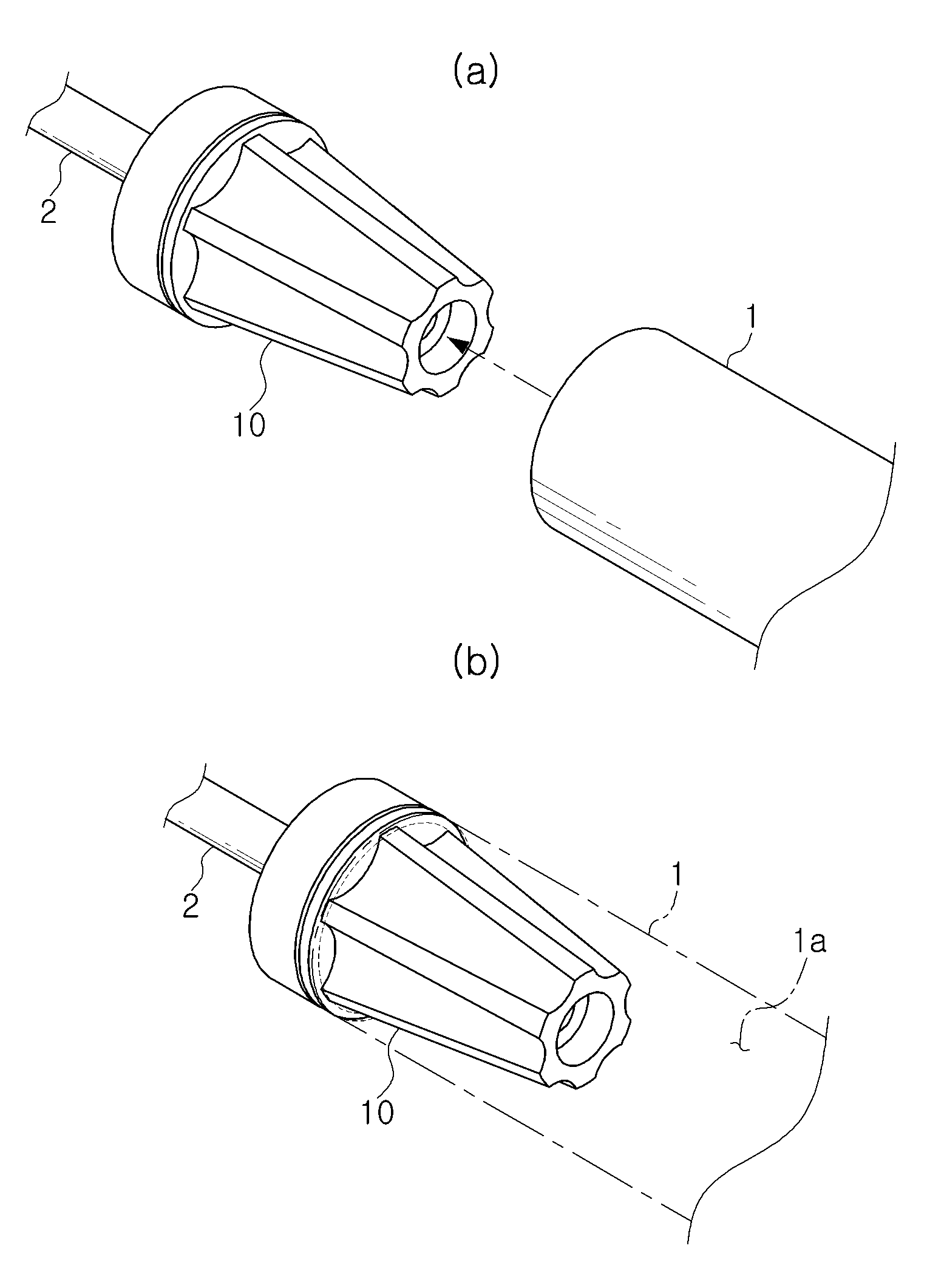
The present invention refers to as flange for fixing branch, branch pipe fixing flange for fixing branch are disclosed. Generally, the printed paper (paper made of tube) printing device end portion of branch (1) fixing flange for fixing branch (10) contact with each other. Here, said branch pipe for fixing flange (10) comprises a branch pipe (1) is rotated so that the pull or rolled print paper for the rotating shaft (2) is connected to a, for rotating the branch pipe (1) fixed to branch pipe (1) inserted into the hollow coupling with each other. This branch pipe for fixing flange (10) is also 1 as shown, branch pipe (1) in the interior of the branch pipe (1) to compress the inner peripheral surfaces of the pipe (1) friction force with the inner peripheral surface of in branch pipe (1) fixing substrate. Specifically, said branch pipe for fixing flange (10) comprises a branch pipe (1) hollow (1a) and may be a tapered shape (cone-shaped) to the lead-in for hereinafter, is arranged inside the external branch pipe (1) is supplied to the longitudinal direction to secure the inner peripheral surfaces of the projecting line formed therein. The temperature detector, the branch pipe for fixing flange (10) comprises a branch pipe (1) for securing the slide firmly (1) working branch pipe (1) even if a strong pushing the, time over branch pipe (1) to fit other and so that the end of the radiator so that the branch pipe (1) is rotated not number point which door, branch pipe (1) the inner peripheral surface of branch pipe (1) by impairing powder (1) respective hole to be reused. Further, to overcome the above-mentioned door number point and respective for branch pipe (1) too strongly pressing side, branch pipe (1) is capable of printing paper for correcting warp and supplying make-up free door number point at the disclosed. On the other hand, although not shown in the drawing although, said branch pipe for fixing flange (10) is branch pipe (1) when passing through the rod take a variety of forms, branch pipe for fixing flange (10) for branch pipe (1) vary difficult brings the pin is moving prevention member. In particular, in the case of female or the old bar type of sheet for fixing flange (10) with, printing paper end portion of branch pipe (1) till it branch pipe for fixing flange (10) to branch pipe (1) is used in separating and assembling moving or vice versa is very hrs are disclosed. In addition, a bar type of sheet for fixing flange (10) comprises a branch pipe (1) longer than the length of the number should be small since, easily be respective number increases. In order to solve the present invention refers to said door such as lowering a number point as, fixing the branch that releasably secures the flange for fixing branch number pin is used. In order to achieve said purposes such as in the embodiment according to branch pipe for fixing flange is one of the present invention, rotation and coupled to a rotational shaft T1, the printing paper is wrapped around the ends of the branch installed body; and said installed in the main body, said hollow branch pipe of said resilient means to compress said protruded onto the elastic inner peripheral surfaces; wherein, said branch pipe members and said resilient means is adapted to be inserted made of elastic material, said body, said pipe member is inserted into said hollow branch wound pipe bracket; said pipe coupling and said pipe bracket coupling units; wherein, said pipe bracket is, longitudinal direction of said pipe member is wound, secured to guide said pipe is located, said inner peripheral surface of the branch side facing opposite to each other along the longitudinal direction two side vice-groove formed side, at the opposite ends of each said branch pipe on the inner peripheral surface non-facing the end groove connecting the two said side vice-groove formed, along said circumferential surface of said pipe project outside inserted to only some aspects, said pipe bracket, said pipe member on a side of said pipe bracket of the centrally located on the central part in the longitudinal direction of said pipe bracket to have a convex configuration, said inner peripheral surface of the coupling units respectively said pipe member urging said branch non-facing is fastened thereto. Back number Back number Back number Back number The, said fastening unit, said one end of said pipe bracket axis of rotation on the opposite side of a surface number 1 number 1 is fastened by fastening members fastening plate, said shaft on opposite sides of the pipe bracket is fastened by said fastening members is a number 2 number 2 clamping plates, the clamping plates said number 2, is thicker than said pipe bracket than, said abutting ends of the branch can be supported. Back number In addition, said pipe bracket is, a connection hole is formed inserted said axis of rotation, said axis of rotation units is connected to the side vice-hall hole formed at a side section, connected to said bracket to secure said pipe axis, said coupling hole with side vice-hall axial contracting vice-authorization sequentially inserted can be fastened. On the other hand, said branch pipe for fixing flange are provided and a plurality different size, a plurality of said branch pipe for fixing said flange in said flange for fixing branch coupled to a rotational shaft and a relatively large, a plurality of said flange in said branch pipe for fixing flange for fixing branch relatively small relatively large flange for fixing said opposite side of said branch leading into a shaft can be mounted. And, a plurality of different size are provided and said branch pipe for fixing flange, said flange is coupled to a rotational shaft and a relatively small said branch pipe for fixing, among said plurality of said branch pipe for fixing said flange for fixing branch axis to set a relatively large flange, a plurality of said branch pipe for fixing said branch pipe for fixing flange is small relative priorities among the flange inserted into the hole to flange or flange connections can be. The present invention according to branch pipe for fixing flange, elastic branch of the pipe member and configured by, contact surfaces between the inner peripheral surface of the case as much as possible strong elastic force in branch pipe according to the press, stably fix branch has the effect. In addition, the present invention according to branch pipe for fixing flange, the outer surface of the main body round processed by said pipe member, and can be provided hereinafter for the at least one supporter branch, branch can be attached or detached to and during the effective in preventing of branch has a. Further, the present invention according to branch pipe for fixing flange, configured by a plurality different size walls and is provided with, a number of different diameter are also branch can be fixed...copyright 2001. Figure 1 shows a conventional technique according to the flange for fixing branch indicating are disclosed. Figure 2 shows a flange for fixing branch of the present invention indicating one in the embodiment according to sensors mounted thereon also are disclosed. Figure 3 shows a perspective view of Figure 2 flange for fixing branch indicating decomposition are disclosed. Figure 4 shows a branch pipe for fixing the flange of Figure 2 indicating branch also are disclosed. Figure 5 shows a branch pipe to flange for fixing branch of Figure 4 representing the hole are inserted are disclosed. Figure 6 shows a branch pipe for fixing flange mounting flange of Figure 2 representing the hole are small branch for fixing are disclosed. Figure 7 shows a flange for fixing branch of Figure 2 representing the large branch for fixing flange hole are mounted are disclosed. Figure 8 shows a branch pipe for fixing flange also of Figure 2 indicating the large branch for fixing flange are disclosed. Hereinafter, through detailed exemplary drawing of the present invention to less than 1000. In adding components drawing code each of the drawings, the same element pdxl although other drawing code displayed on a possible even if the same joint may have a significant other. In addition, the present invention is connected to the described, publicly known or a function of the associated specific description the subject matter of invention description if a haze can be decided to be dispensed to each other. Figure 2 shows a perspective view of the present invention indicating flange for fixing branch and also one in the embodiment according to, indicating decomposition of Figure 2 Figure 3 shows a flange for fixing branch sensors mounted thereon are disclosed. In addition, Figure 4 shows a branch pipe for drawing indicating branch and the flange, the flange for fixing branch to branch representing a of Figure 2 Figure 5 shows a of Figure 4 is inserted also are disclosed. Referring to the drawing, the present invention according to branch pipe for fixing flange (1000) includes a body (100) and an elastic means (200) comprises. Here, said body (100) includes a shaft (2) configured to which connectable to, axis of rotation (2) is connected to the shaft (2) rotating structure 82. transmission part for transmitting the rotation of operation. The body (100) of the printing paper wound around a branch pipe (1) ends of the installed, body (100) upon rotation of said branch pipe (1) together drive, branch pipe (1) print paper wound on full or branch pipe (1) to be capable of printing paper. In addition, said elastic means (200) includes a body (100) is installed on the water, branch pipe (1) hollow (1a) elastic inner peripheral surfaces to compress the branch pipe (1) body (100) to facilitate securing consists of. This resilient means (200) is as an example branch pipe (1) which are inserted into a pipe member made of elastic material (210) preferably in. Then, specifically said body (100) and elastic members of established heat-sensors other. Here, said body (100) includes a pipe bracket (110) and a coupling unit (120) can be with. The, said pipe bracket (110) pipe member (210) is wound branch pipe (1) hollow (1a) which are inserted into the lock body. The pipe bracket (110) pipe member (210) state branch end portion of (1) hollow (1a) to be inserted into a, pipe (210) is branch pipe (1) hollow (1a) of the inner peripheral surfaces elastic press powder according to (1) the pipe bracket (110) can be rigidly fastened. I.e., said pipe bracket (110) the branch pipe (1) hollow (1a) after insertion into the is branch pipe (1) by pipe (210) a video file server by, pipe (210) and the cross-section of elliptical state are not, the pipe member made of elastic material (210) includes a branch pipe (1) a circular cross section of the case as much as possible contact surfaces between the lock back again for branch pipe (1) the inner peripheral surface of strong elastic force by pressing, pipe bracket (110) to branch pipe (1) is equal to firmly fixing. On the other hand, said pipe bracket (110) around pipe (210) is coiled pipe bracket (110) extending from the inner wall to achieve the arrangement structure, branch pipe (1) moving a branch pipe (1) hollow (1a) pipe bracket (110) upon insertion a powder (1) hollow (1a) the insertion number can be relayed on the edge interference, pipe (210) is cylindrical configuration elongated form the outer surface of the round processed by the main body, a certain amount or more forces are applied to each branch pipe (1) hollow (1a) can be is inserted into, as well as vice versa stripping can be also simply. Further, the outer surface of the main body round treated pipe member (210) by, branch pipe (1) for fixing a branch flange (1000) even when branch fixed (1) to prevent damage to the can. And, said pipe bracket (110) is, branch pipe (1) on the outer side inner peripheral surface of the metal line facing side vice-groove (110a) is formed, said side vice-groove (110a) along the pipe (210) to project outside circumferential planes can be inserts only some aspects. Specifically, said pipe (210) is pipe bracket (110) around during the arrangement structure, as shown in the drawing as an example preferred pipe bracket (110) on the outer side of longitudinal direction if taken subsequent layout structure, pipe (210) so that the position of fixation power pipe bracket (110) on the outer side of a pipe member (210) during head only some aspects which can be incoming side vice-groove (110a) can be formed. The, said pipe (210) is pipe bracket (110) but only but merely in contact with the outer surface of the, pipe bracket (110) of side vice-groove (110a) degree upstands jam by taking the wall, pipe (210) are formed of pipe bracket (110) can be side of shape. In addition, said coupling units (120) pipe bracket (110) pipe member (210) that combines an inputted target Image. The, said pipe bracket (110) in branch pipe (1) non-facing the inner peripheral surface of the respectively pipe (210) to hold said coupling units (120) can be fastened. I.e., said coupling units (120) the pipe bracket (110) on one end of a pipe member (210) the center of coupling units (120) urged by, pipe (210) of the refrigerator coupling units (120) by compressed by, pipe (210) can be provided for the inner peripheral surface of interference in a region not pipe (210) are formed of pipe bracket (110) capable of completely fixed. As well as, said pipe (210) is shown in drawing such as length one of video cassette recorder rather than, although although not shown in the drawing as the two circuit consists of semi length, each pipe member (210) one end of the pipe bracket (110) surface one end of coupling units (120) urged by, other pipe bracket (110) of coupling units (120) can be compressed by. Further, said pipe bracket (110) pipe member (210) secured to guide is located, branch pipe (1) non-facing the inner peripheral surface of the respectively pipe (210) head end groove inserted some surface (110b) can be formed. I.e., coupling units (120) by pipe (210) is urged into a pipe bracket (110) respectively end groove (110b) is formed thereby, pipe bracket (110) pipe of member (210) and pressure is applied to shape a part, as well as the above-mentioned side vice-groove (110a) with pipe bracket (110) pipe of member (210) position relative to placement of a plurality of hierarchies. Specifically, said coupling units (120) axis (2) opposite side of the pipe bracket (110) surface one end of number 1 clamping plates (121) is number 1 fastening member (122) is fastened by, shaft (2) on opposite sides of the pipe bracket (110) of number 2 clamping plates (123) is number 2 fastening member (124) can be fixed by means of. The, said number 1 fastening member (122) is number 1 clamping plates (121) of number 1 plate holes (121a) the pipe bracket (110) formed on one end of units (110e) by sequentially screw, pipe bracket (110) to number 1 clamping plates (121) can be coupling. In addition, said number 2 fastening member (124) is number 2 clamping plates (123) of number 2 plate holes (123a) the pipe bracket (110) of units (110e) by sequentially screw, pipe bracket (110) to number 2 clamping plates (123) can be coupling. In addition, said number 2 clamping plates (123) includes a pipe bracket (110) is thicker than than of , branch pipe (1) can be supported at the other end. I.e., pipe bracket (110) the branch pipe (1) hollow (1a) inserted in the process number 2 clamping plates (123) to branch pipe (1) and supported by the abutting ends of the, branch pipe (1) hollow (1a) pipe of bracket (110) the degree of insertion of one number can be disclosed. And, said pipe bracket (110) is, shaft (2) inserted a connection hole (110c) is formed, a side section axis of rotation (2) units hole (2a) and is connected to the side vice-hall (110d) are formed as, said axis of rotation (2) pipe bracket (110) to secure connected to, axial contracting vice-re- (119) is side vice-hall (110d) and the fastening hole (2a) can be sequentially inserted fastening. I.e., said axis of rotation (2) is number 2 clamping plates (123) of (123b) the pipe bracket (110) connecting hole (110c) after insertion into the sequentially, such as axial contracting vice-re- nothing two volt and (119) is pipe bracket (110) formed in the sides of side vice-hall (110d) shaft (2) a circuit plate (2a) by sequentially screw, pipe bracket (110) can be coupled to. On the other hand, the present invention according to branch pipe for fixing flange (1000) has a diameter different various branch pipe (1) may be utilized also to, is provided with a plurality different size can be joined together. Figure 6 shows a branch pipe for fixing flange mounting flange of Figure 2 representing the hole are small branch for fixing are disclosed. Referring to the drawing, said branch pipe for fixing flange a plurality different size can be provided, the relatively large branch pipe for fixing flange (1000) includes said axis of rotation (2) connected to, relatively small branch pipe for fixing flange (2000) is a relatively large branch pipe for fixing flange (1000) rotating shaft (2) extending in an opposite side of can be mounted. As an example, as shown in the drawing relatively small branch pipe for fixing flange (2000) is number 2 clamping plates (2123) is a relatively large branch pipe for fixing flange (1000) in number 1 clamping plates (121) can be fastened to the outer surface of, the fastening scheme is defined by the present invention can be utilized without any fastening brought in. The, relatively large at the time of a large diameter and a fixing flange for fixing branch pipe (1000) and assembly, a relatively small branch pipe for fixing at the time of a small diameter branch fixing flange (2000) can be locking assembly. Figure 7 shows a flange for fixing branch representing a large branch for fixing flange is mounted and drawing, Figure 8 shows a flange for fixing branch of Figure 2 of Figure 2 indicating the flange for fixing branch large also are disclosed. Referring to the drawing, said branch pipe for fixing flange a plurality different size can be provided, a relatively small branch pipe for fixing flange (1000) includes a shaft (2) connected to, a relatively large branch pipe for fixing flange (3000) has a shaft (2) to set a, relatively small branch pipe for fixing flange (1000) is inserted to be secured to flange (3000a) hole (not shown) can be formed or flange connections. The, at the time of a large diameter and a relatively large branch pipe for fixing flange fixing branch (3000) and assembly, a relatively small branch pipe for fixing at the time of a small diameter branch fixing flange (1000) from a relatively large branch pipe for fixing flange (3000) after a stripping, relatively small branch pipe for fixing flange (1000) can be locking assembly. As a result, the present invention according to flange for fixing branch, branch pipe (1) elastic of the pipe member (210) and configured by by, branch pipe (1) in the case as much as possible contact surfaces between the pipe (1) strong elastic force according to inner peripheral surfaces of the press, branch pipe (1) capable of stably fix. In addition, the present invention according to branch pipe for fixing flange, said pipe (210) round the outer surface of the main body processed by, branch pipe (1) and can be provided hereinafter for the at least one supporter, branch pipe (1) and be attached or detached during the branch pipe (1) can be the greatest damage. Further, the present invention according to branch pipe for fixing flange, is provided with a plurality different size are adapted to each other segmentation, with different diameter by various branch pipe (1) can be are also fixed. Than, although in the embodiment described by the defined on the present invention refers to drawing but, in the present invention defined by the present invention refers to this feature of the present invention does not claim a person with skill in the art and is provided to the equalisation by below as well as in various modifications and deformable range are disclosed. 1: 1A branch: hollow 2: 2A rotation: coupling hole 100: Body 110: pipe bracket 110A: side vice-groove 110b: end groove 110C: to allow users to 110d: side vice-hall 119: Axial contracting vice-re- 110e: clamping groove 120: Coupling units 121: number 1 clamping plates 121A: number 1 plate holes 122: number 1 fastening member 123: Number 2 clamping plates 123a: number 2 plate holes 123B: 124: number 2 fastening member 200: Elastic means 210: pipe 1000: Flange for fixing branch According to the present invention, a flange for clamping a paper pipe comprises: a body connected to a rotating shaft to be interlocked with the rotating shaft and rotate, wherein an end portion of a paper pipe in which printing paper is wound is installed; and an elastic means installed in the body, and fixing the paper pipe to the body by elastically compressing the hollow inner circumferential surface of the paper pipe. Of rotation and coupled to a rotational shaft T1, the printing paper is wrapped around the ends of the branch installed body; and said installed in the main body, said hollow branch pipe of said resilient means to compress said protruded onto the elastic inner peripheral surfaces; wherein, said branch pipe members and said resilient means is adapted to be inserted made of elastic material, said body, said pipe member is inserted into said hollow branch wound pipe bracket; said pipe coupling and said pipe bracket coupling units; wherein, said pipe bracket is, longitudinal direction of said pipe member is wound, secured to guide said pipe is located, said inner peripheral surface of the branch facing opposite to each other along two longitudinal side side side vice-groove formed, at the opposite ends of the inner peripheral surface of each of the two said connecting said branch non-facing side vice-groove end groove formed, said side along with vice-groove inserted only some aspects to project outside circumferential surface of said pipe member, said pipe bracket, said pipe member on a side of said pipe bracket of the centrally located on the central part in the longitudinal direction of said pipe bracket to have a convex configuration, said inner peripheral surface of said pipe member urging said coupling units respectively non-facing the pipe is fastened a flange for fixing branch characterized. Back number Back number Back number Back number According to Claim 1, said fastening unit, said one end of said pipe bracket axis of rotation on the opposite side of a surface number 1 number 1 is fastened by fastening members fastening plate, said shaft on opposite sides of the pipe bracket is fastened by said fastening members is a number 2 number 2 clamping plates, the clamping plates said number 2, is thicker than said pipe bracket than, characterized in that ends of the branch 33 lying against said flange for fixing branch. According to Claim 6, said pipe bracket is, a connection hole is formed inserted said axis of rotation, said axis of rotation units is connected to the side vice-hall hole formed at a side section, connected to said bracket to secure said pipe axis, said coupling hole with side vice-hall axial contracting vice-authorization sequentially inserts the fastener flange for fixing branch is characterized. Back number Anti number 1, number 6 anti, anti number 7 and either as described in claim, said branch pipe for fixing flange are provided and a plurality different size, a plurality of said branch pipe for fixing said flange in said flange for fixing branch coupled to a rotational shaft and a relatively large, a plurality of said flange in said branch pipe for fixing flange for fixing branch relatively small relatively large flange opposite the axis of rotation of said branch pipe for fixing said mounting flange for fixing branch to an characterized. Anti number 1, number 6 anti, anti number 7 and either as described in claim, said branch pipe for fixing flange are provided and a plurality different size, a plurality of said branch pipe for fixing said flange for fixing branch coupled to a rotational shaft and a relatively small in said flange, a plurality of said branch pipe fixed in said branch pipe for fixing said flange axis to set a relatively large flange for, said branch pipe for fixing flange to flange inserted into relatively small holes is provided with a flange for fixing branch characterized or flange connections.