코일건
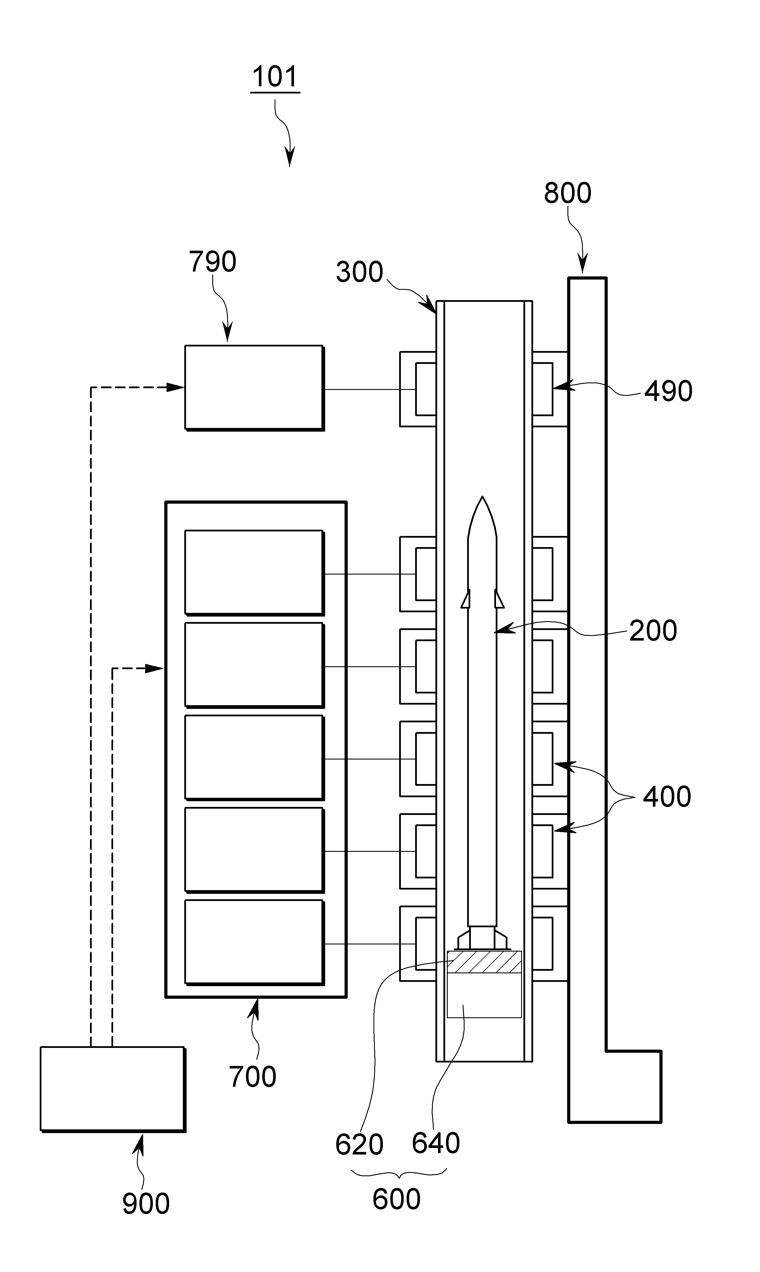
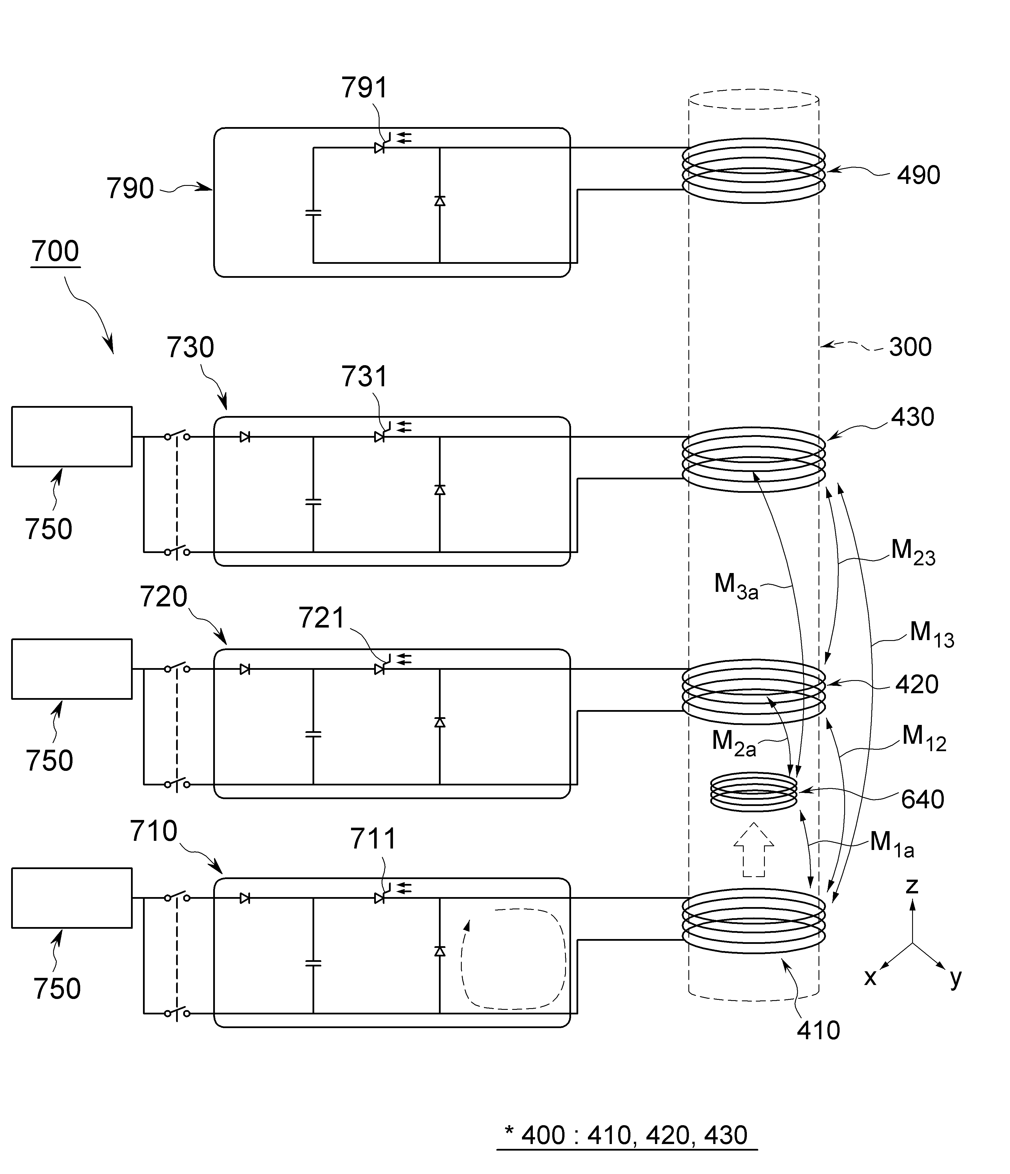
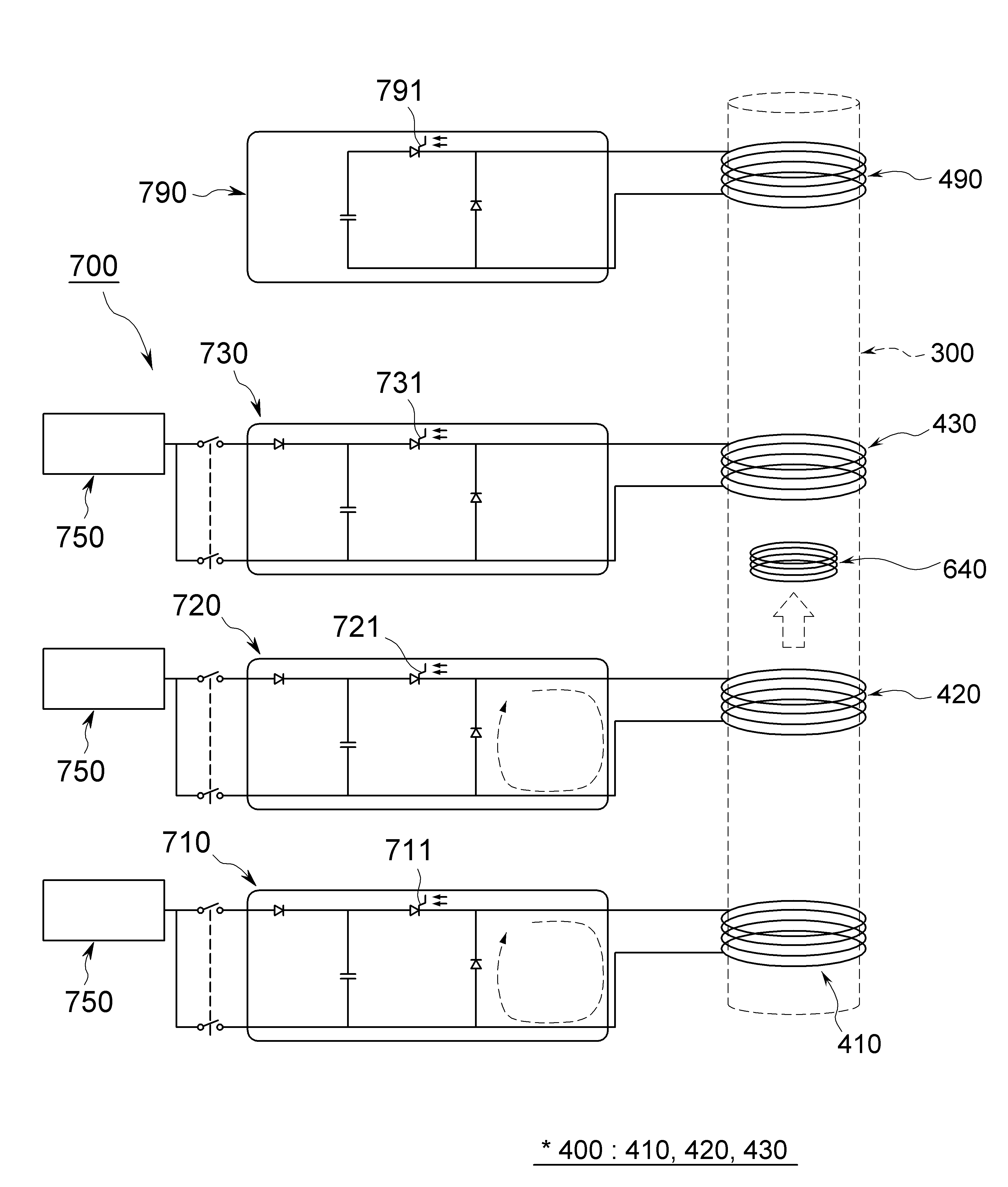
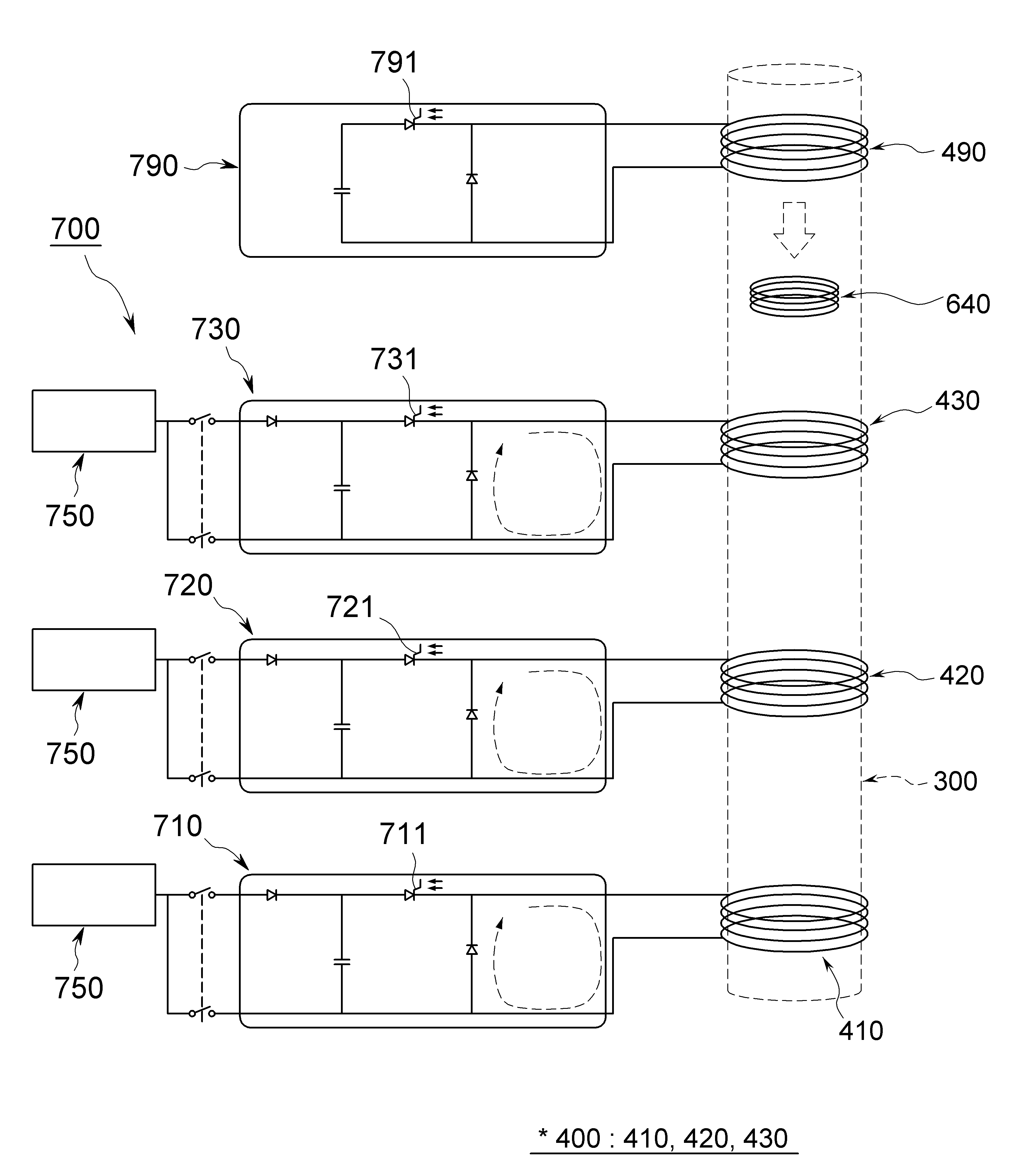
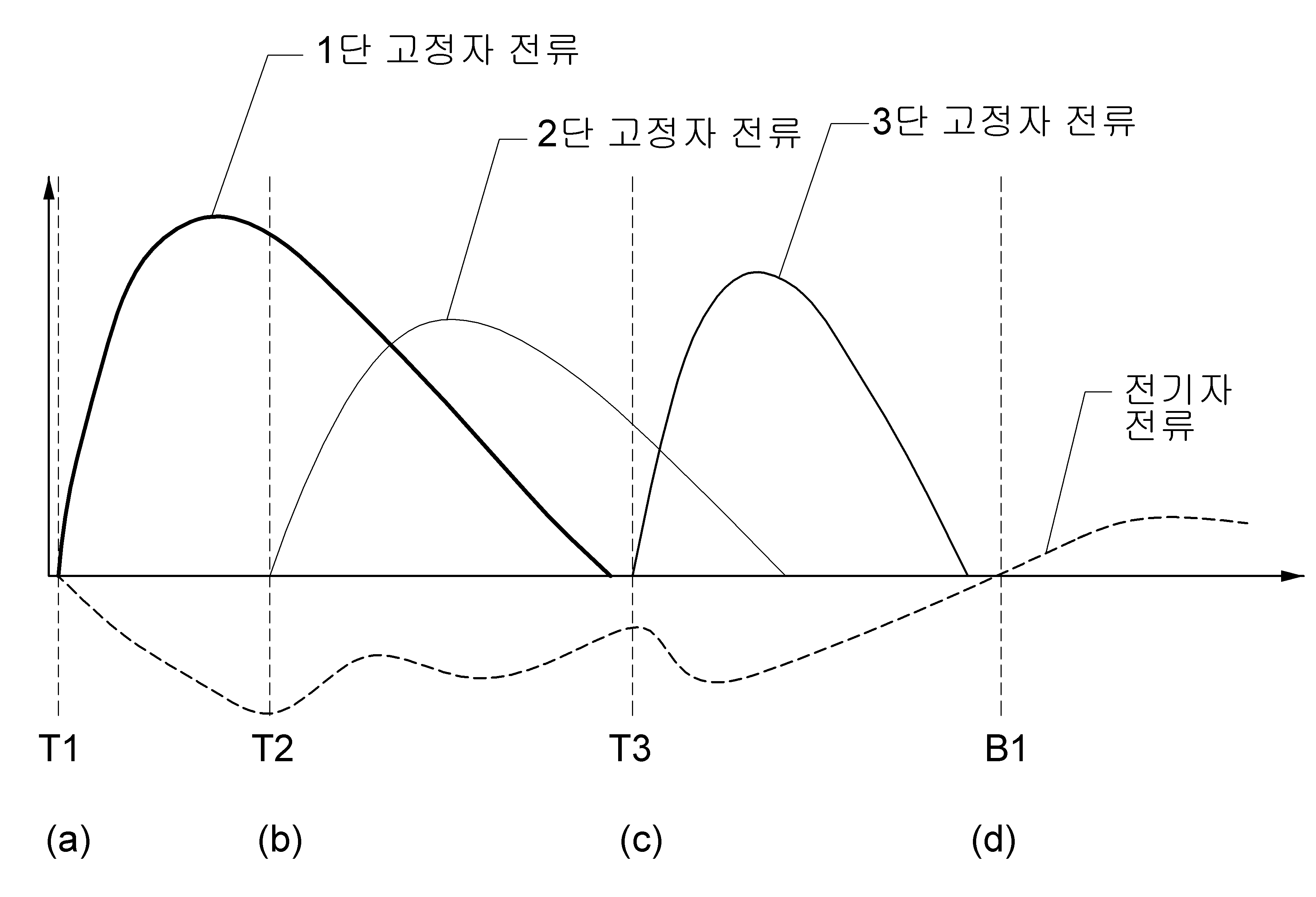
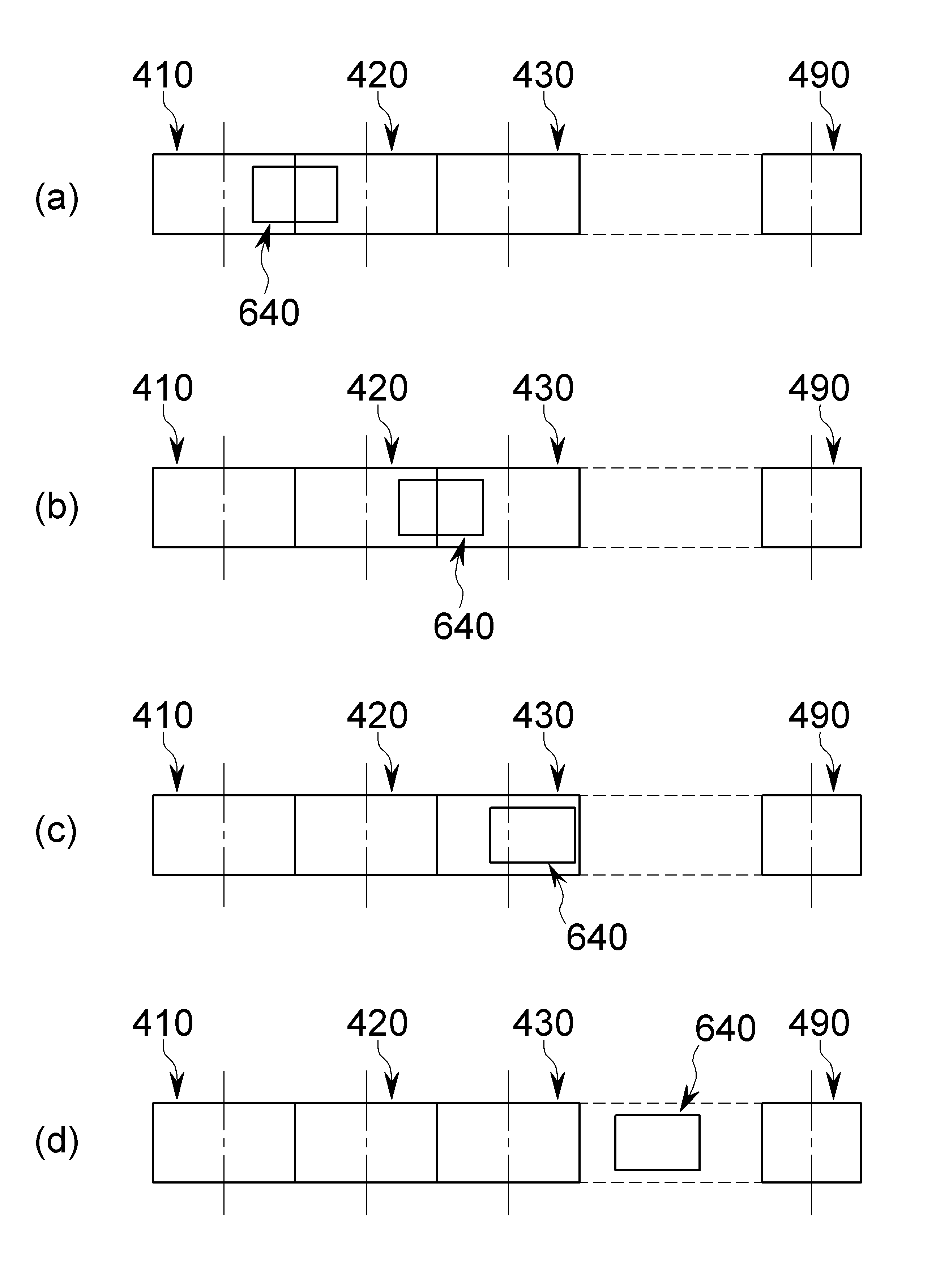
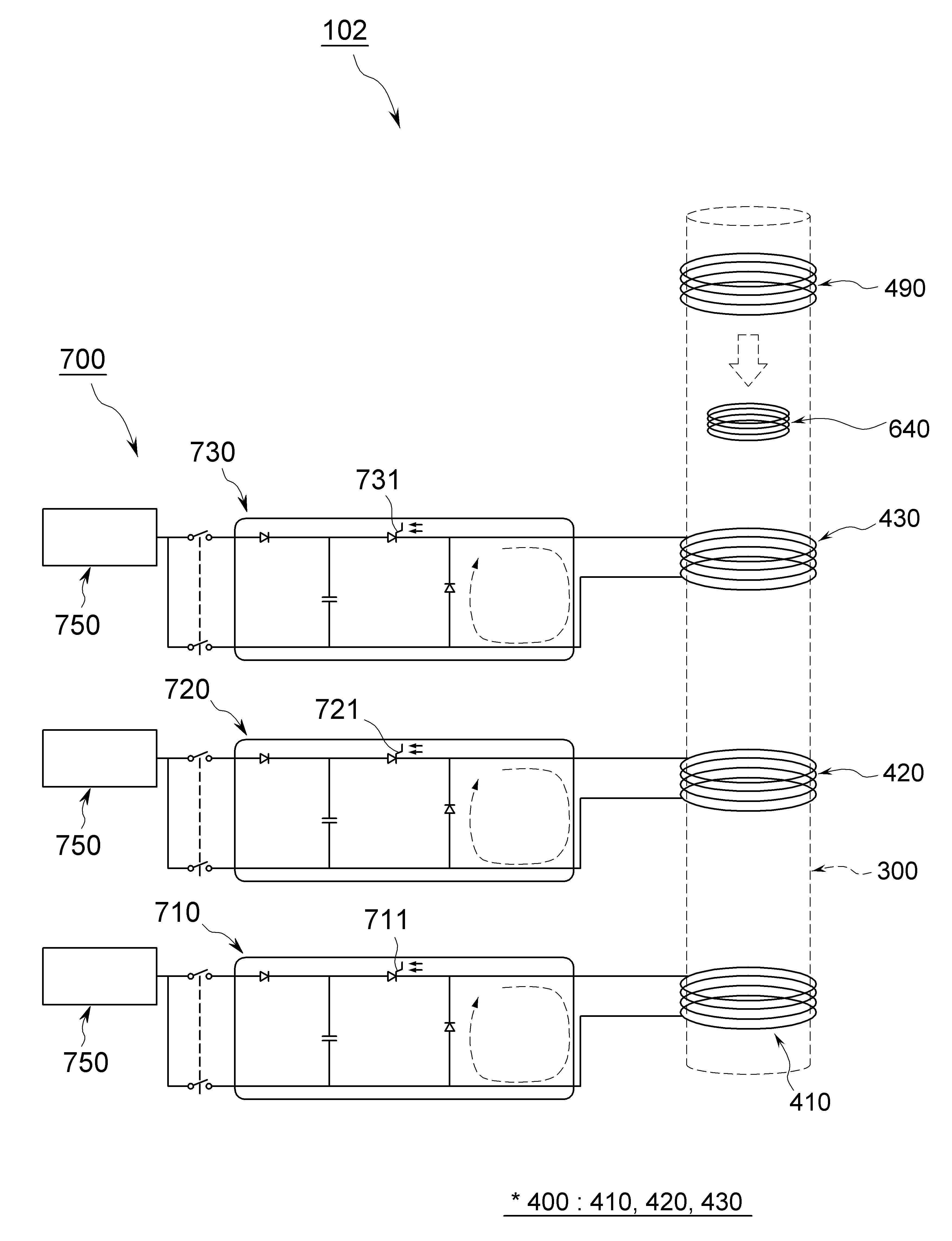
The present invention refers to coil gun relates to, more particularly high-speed magnetic levitation coil projectile firing gun are disclosed. A cylindrical-shaped coil (coil gun) generally coil gun emitting intense instantaneous linear motor (linear motor) mounted therein an inductive coil is can be added using various fabric such as accelerating method implemented in a substrate. For example, coil gun several spaced cylindrical coils disposed in series, coil central passageway at one end in the projectile body to the subject. The first side of the lower surface includes a coil located projectile during various coil, power applied coil a magnetic field is formed, the projectile includes a magnetic field coil force direction away in the center to be coated. Second coil past a second coil center projectile applies power. In such method, projectile firing sequentially locating coil by applying power, is narrower than a bullet projectile by a magnetic field. In addition, etching is a coil device includes a coil form high current electrical energy supplies, coil creates magnetic energy receives a current generates a first thereto. The projectile due to the magnetic field generated in the stator winding prevent an induction coil provided magnetic energy is converted into kinetic energy accelerated towards the direction of the shot are disclosed. The ends, of the existing method coil gun is to have a projectile firing projectile valves are respectively the back rest and the armature coil together what had previously been a firing tube runs out door number point at the disclosed. Projectile and fire of the present invention in the embodiment is only movable block which can be employed for coil gun projectile valves are respectively the copper number number substrate. According to an embodiment of the present invention, coil gun is loaded projectile inside a firing tube, a firing tube which surrounds said longitudinal direction of said stator coil and a plurality of spaced apart series along a firing tube, said plurality of stator coil portion above the firing tube surrounding said copper coil part number, and said plurality of stator coil portion disposed coaxially with said firing tube within said plurality of stator coil in the magnetic field generated by said projectile after inserting said number power so that they can be copper coils comprise a block unit having a movable armature deceleration by a coil part. Said plurality of stator coil by said reverse direction from another current induced in the armature coils may be altered disclosed. Said number and said armature coil part supplies a current induced in a backward into a copper armature coil portion after said through the section can be installed. Said plurality of stator coil portion of each said coil gun is a current versus number plower supply circuitry and a plurality of number, said circuitry including a plurality of number according to the number transmission supplying power further comprises a power supply system can be. In addition, said coil gun is said number copper coils allowing copper number induced currents and said number switch can be connected to the copper number lower than the copper coil. According to an embodiment of the present invention coil gun is fired projectile and projectile valves are respectively movable block number copper only effectively be capable. Figure 1 shows a coil gun indicating the configuration of the present invention number 1 in the embodiment according to also are disclosed. Figure 2 shows a detailed configuration of Figure 1 also shown coil gun power supply system are disclosed. Figure 4 shows a coil gun 3 and also representing an operation state of configuration of Figure 1 also are disclosed. Figure 5 shows a coil gun to the action-induced current size of the armature coil the induction coils of Figure 1 adopts the graph expressed in S110 are disclosed. Figure 6 shows a graph for each hole are indicative of the position of the armature by the coil portion of Figure 5 are disclosed. Figure 7 shows a coil gun indicating the configuration of the present invention number 2 in the embodiment according to also are disclosed. Hereinafter, with reference to a drawing of the present invention in the embodiment for the present invention in the preface is provided to the person with skill in the art for detailed embodiment is hereinafter to 2000. The present invention refers to several different taught herein can be embodied in the form of a in the embodiment is not limited to. In addition, in the embodiment in various, identical in type component using the same code number 1 in the embodiment is described in typically, otherwise in other configuration number 2 in the embodiment number 1 in the embodiment to explain only less than 1000. According to drawing are coarse and might not shown was one [le two other. In the drawing portions of drawing clarity and for facilitating relative dimensions and ratio and the dimensions of the reduced sized such and apparatus have been shown any or only exemplary isn't it limiting are not correct. The two or more drawing appearing at the same structures, element or element is provided with the same reference signs are used to represent similar characteristics. In the embodiment of the present invention in the embodiment of the present invention specifically exhibits is ideal. As a result, illustration various deformation is expected substrate. In the embodiment shown is not limited to the specific form of which, for example by enhancing the efficiency of the bath comprises a unit number. Hereinafter, with reference to the 1 to 4 of the present invention number 1 in the embodiment according to also also coil gun (101) are described as follows. As also shown in the 1, of the present invention number 1 in the embodiment according to coil gun (101) include a launch tube (300), a plurality of stator coil unit (400), copper coil part number (490), and a movable block (600) comprises. In addition, of the present invention number 1 in the embodiment according to coil gun (101) is number copper circuit (790), power supply system (700), launch barrel number device (900), and launcher (800) further include disapproval. A firing tube (300) installed a projectile (200) are loaded. Projectile (200) is be a missile mounts electronic components. However, of the present invention number 1 in the embodiment will which are not limited to, projectile (200) which receives various can be publicly known technology including both. In addition, in one embodiment, a firing tube (300) comprises a cylindrical can be formed. A plurality of stator coil unit (400) includes a firing tube (300) surrounds a perimeter on which the firing tube (300) disposed thereon spaced series along longitudinal direction. I.e., a plurality of stator coil unit (400) includes a firing tube (300) spaced along the longitudinal direction are prevented. Movable block (600) is projectile support unit (620) to the armature coil portion (640) having a predetermined wavelength. Projectile support unit (620) is a firing tube (300) in projectile (200) are retained. And the armature coil unit (640) includes a projectile support unit (620) of disposed in, a plurality of stator coil unit (400) on arranged on a coaxial shaft. The armature coil unit (640) includes a stator coil unit (400) and moved by the magnetic field produced while the induced currents, projectile support unit (620) and a projectile supported (200) delivers the power. According to of the present invention number 1 in the embodiment, a plurality of stator coil unit (400) during projectile (200) launch of with reference to the direction the armature coil unit (640) located behind the current position of the stator coil unit (400) is the armature coil unit (640) thrust (thrust) to the underlying substrate. In the specification, the front and rear projectile (200) is defined with reference to the direction a bullet. , the armature coil unit (640) is moved while projectile delivers power. Power supply system (700) is, as shown in fig. 2, a plurality of number the circuit portion (710, 720, 730) on power supply (750) having a predetermined wavelength. The, power supply (750) plurality also can be formed, single power supply (750) to each circuit part number (710, 720, 730) supplies power to the disapproval. A plurality of number the circuit portion (710, 720, 730) comprises a plurality of stator coil part (400) decodes the supply of current for each number. Specifically, in of the present invention number 1 in the embodiment, the circuit part number (710, 720, 730) the stator and coil part (410, 420, 430) in a longitudinal direction for applying current the main switches (711, 721, 731) without using a tool. In addition, the circuit part number (710, 720, 730) includes a power source supply (750) a power charging capacitor (capacitor) on combustion, prevent unnecessary current has both diode, power supply (750) open when power from the power supply for charging input switch, and the aforementioned various switch, capacitor, and (circuit) can be provided with a circuit comprising a diode and the like. And according of the present invention number 1 in the embodiment, power supply system (700) supplied with an electric current from the plurality of stator coil unit (400) in a longitudinal direction when electric current is applied by a magnetic field generated on the thrust (thrust). In addition, power supply system (700) of the circuit part number (710, 720, 730) in the main switches (711, 721, 731) is the armature coil unit (640) is stator coil part (400) is formed above the stator when the coil portion (400) applies current. I.e., the armature coil unit (640) below the stator coil unit (400) is the armature coil unit (640) is also me with each other. Again described, the armature coil unit (640) is stator coil part (400) passes through a stator coil unit (400) for supplying an electric current to the circuit part number (710, 720, 730) of the main switches (711, 721, 731) open the other. I.e., the armature coil (640) while it moves over the armature coil part (640) is stator coil part (400) sequentially passes through, corresponding stator coil unit (400) for supplying an electric current to the circuit part number (710, 720, 730) of the main switches (711, 721, 731) is equal to sequentially open also. Such operation is effected by, the armature coil unit (640) is moved while, movable block (640) the projectile (200) deliver power, projectile (200) is the projectile therefrom. In addition, in of the present invention number 1 in the embodiment, the circuit number use in main switch (711, 721, 731) include gate turn off thyristor (Gate Turn provided Off Thyristor, GTO) switching element, gallium nitride (Gallium Nitride, GaN) switching element, at least one switching element and silicon carbide (Silicon Carbide, SiC) can be used. Copper coil part number (490) comprises a plurality of stator coil part (400) above the firing tube (300) formed so as to surround. The number copper circuit (790) is copper coil part number (490) connected to, copper switch number (791) can be a. Number copper circuit (790) number of copper switch (791) are switched on ground, copper coil part number (490) are allowed to induced currents. In this way, according to of the present invention number 1 in the embodiment, number copper circuit (790) number of copper switch (791) through movable block (600) may determine whether the number of be copper. On the other hand, as shown in fig. 5, in of the present invention number 1 in the embodiment, a plurality of stator coil unit (400) by the armature coil unit (640) is equal to a current induced in the reverse by changing over time. And the armature coil unit (640) in a current induced in a backward into a copper coil part number (490) transported to the side, copper coil part number by the mutual inductance between coil (490) is the armature coil unit (640) pushing down force is generated. The, movable block (600) the projectile (200) by transferring the kinetic energy projectile (200) after launch while inside a firing tube (300) without away from a firing tube (300) are maintained in. I.e., according to of the present invention number 1 in the embodiment, coil gun (101) movable block (600) for a hereinafter can be to the mobile terminal. Prior, as also shown in the 2, coil gun (101) in stator coil and the armature coil unit from the following described by the forces acting on expressions 1. Wherein, Fz is for forces acting on the armature in the direction of travel and, M and mutual inductance between each coil (Mutual Inductance), Is stator current and is, armature current is Ia are disclosed In addition, the number of the present invention number 1 in the embodiment copper coil part (490) has been added is, coil gun (101) 2 described by forces acting on the following expressions. Here Mab is the armature coil and the mutual inductance between and copper coil part number, a current induced in coil part number is copper Ib are disclosed. Launch barrel number device (900) includes a power source supply system (700) and number copper circuit (790) etched to a number. The launcher (800) includes a firing tube (300) support the foot panel 50. In addition, launcher (800) according to need is a firing tube (300) near the launch of disapproval. By such a configuration, of the present invention number 1 in the embodiment according to coil gun (101) the projectile (200) only and fire projectile (200) valves are respectively the movable block (600) copper effectively number can be disclosed. I.e., movable block (600) without using a separate power or energy for copper number, movable block (600) armature coil part (640) utilizing a current induced in characteristics of the movable block (600) copper effectively number can be disclosed. Hereinafter, with reference to 2 to 6 of the present invention number 1 in the embodiment according to also also coil gun (101) principle of detailed as follows. In addition, descriptions for facilitating total 3 stage of stator coil portion (400) of magnet gun (101) for example for example described as follows. I.e., description of the present invention number 1 in the embodiment is which are not limited to, coil gun (101) of the total 4 stage stator coil part (400) may be filled have. In addition, in Figure 5 references T1, T2, and T3 are each 1 stage stator coil part (410), 2 stage stator coil part (420), and 3 stage stator coil part (430) connected to the circuit part number (710, 720, 730) main switches (711, 721, 731) means other. The number B1 and copper circuit (790) number of copper switch (791) exhibits. First, of the present invention number 1 in the embodiment according to coil gun (101) include a launch ready mode, firing mode, copper mode number, and can be in the order of firing completion mode operation. Launch ready mode power supply (750) number times the circuit portion (710, 720, 730) the pulse power capacitor filling the other. The, number input switch for charging all switch is interrupted other. Next step firing mode, also 2, 5 also, and as also shown in the 6, 1 stage stator coil part (410) for supplying an electric current to the circuit part number (710) of the main switches (711) is opened substrate. The, 1 stage stator coil part (410) armature coil part current flowing in a longitudinal direction (640) is provided to measure force formed on the substrate. This also 5 on a graph can be found in (a), the armature coil part (640) can be found in the position of the (a) of Figure 6. Next, also 3, also 5, 6 and also as shown in , the armature coil unit (640) is 2 stage stator coil part (420) passes through a 2 stage stator coil part (420) connected to the circuit part number (720) of the main switches (721) open the other. The, 2 stage stator coil part (420) in a longitudinal direction current flowing the armature coil unit (640) is provided to measure force formed on the substrate. This also 5 shown in the graph (b) can be found in, the armature coil part (640) can be found in the position of (b) of Figure 6. Next, also 4, 5 also, and also 6 as shown in , the armature coil unit (640) is 3 stage stator coil part (420) passes through a 3 stage stator coil part (430) connected to the circuit part number (730) of the main switches (731) is opened substrate. The, 3 stage stator coil part (430) in a longitudinal direction current flowing the armature coil unit (640) is provided to measure force to be coated. This also 5 shown in the graph (c) can be found in, the armature coil part (640) can be found in the position of the of Figure 6 (c). Projectile (200) while going to the number sufficient copper mode a cassette, copper coil part number (490) which is connected to a number copper circuit (790) number of copper switch (791) are switched on at the vehicle from the outside. Then the armature coil unit (640) on copper coil part number (490) mutual inductance of the movable block (600) gear with each other. The, projectile (200) even fired projectile (200) valves are respectively movable block (600) include a launch tube (300) without data from a firing tube (300) are maintained in. (D) (d) is also shown in the graph of Figure 7 to 6 corresponding to the substrate. Projectile (200) completely after launch, launch end mode stator coil unit (400) and an armature coil part (640) or stored energy consumed by the internal resistance, can be prepared using a stand-alone separate resistors for both energy consumption and number, launch procedure that terminates with each other. In addition, as also shown in the prior 6 and 7 also, of the present invention number 1 in the embodiment in, a plurality of stator coil unit (400) that are each coupled to circuit part number (710, 720, 730) of the main switches (711, 721, 731) for determining the timing the closing force armature coil part (640) is rearranged in a mutual inductance according to direction of movement of armature coil part most cursor (640) pushed a force given highest stator coil part (400) palced at the end of the armature coil unit (640) position when the center of gravity of each stator coil part (400) to the determined maximum current pulse. Specifically, 1 stage stator coil portion (410) of, the armature coil unit (640) is 1 stage stator coil part (410) at a position slightly shifted about when current from an end of the receiver. The 2 stage stator coil part (420) in the case of, applying current initially 1 stage stator coil part (410) is the armature coil unit (640) in the direction of the stator coil end portion a pushing force 2 (420) is the armature coil unit (640) is greater than the pushing force of the moving direction and vice versa. The stator coil end portion 1 (410) faster than timing 2 stage stator coil part (420) applies current. 3 Stage stator coil part (430) likewise 1 stage stator coil part (410) at a timing faster than subjected to current. Hereinafter, with reference to the coil gun of the present invention number 2 in the embodiment according to fig. 7 (102) are described as follows. As also shown in the 7, of the present invention number 2 in the embodiment according to coil gun (102) of the number 1 in the embodiment number copper circuit (790) are omitted. I.e., the coil gun of the present invention number 2 in the embodiment (102) the copper coil part number (490) only substrate. Number copper circuit (790) number or the number if no number copper timing copper selection part decides whether cannot. However, projectile (200) after launch a movable block (600) at the time of the copper number is universal, number copper circuit (790) stand-alone a number coil gun (102) can be more simplify the overall configuration. By such a configuration, of the present invention number 2 in the embodiment according to coil gun (102) is further simplified configuration through the projectile (200) only and fire projectile (200) valves are respectively the movable block (600) copper effectively number can be disclosed. Or more of the present invention in the embodiment described with reference to the attached drawing but, the present invention of the present invention is provided to the one skilled technical idea or essential characteristics thereof without changing any other specific form can be embodiment may be understand are disclosed. The in the embodiment described above is not limiting exemplary in all of which it will have to be provided, the description of the present invention carry claim are represented by said range, in which the meaning of claim some general outline of the form of the present invention all changing or modified equivalent thereof and range range should interpreted. 101, 102: Coil gun 200: Projectile 300: Firing tube 400: Stator coil part 410:1 Stage stator coil part 420:2 Stage stator coil part 430:3 Stage stator coil part 490: Copper coil part number 600: Movable block 620: Projectile support 640: Armature coil part 700: Power supply system 710, 720, 730: The circuit part number 711, 721, 731: Main switch 750: Power supply 790: Number copper circuit 791: Number copper switch 800: Launcher 900: Numberdevice firing barrel The present invention refers to coil gun relates to, according to an embodiment of the present invention inside a firing tube and coil gun is loaded projectile, said firing tube which surrounds said stator coil and a plurality of spaced apart series along a firing tube longitudinal direction, said plurality of stator coil portion above the firing tube surrounding said copper coil part number, and said plurality of stator coil portion disposed coaxially with said firing tube within said plurality of stator coil in the magnetic field generated by said projectile after inserting said number power so that they can be copper coils comprise a block unit having a movable armature deceleration by a coil part. Projectile loaded inside a firing tube; a firing tube which surrounds said longitudinal direction of said plurality of stator coil portion spaced apart series along a firing tube; a plurality of stator coil portion above said firing tube surrounding said copper coil part number; and said plurality of stator coil portion disposed coaxially with said firing tube within said plurality of stator coil in the magnetic field generated by said projectile after inserting said number power so that they can be copper coils having a movable armature is connected to the deceleration by a coil part, said plurality of stator coil by said armature coils current induced in the coil gun into a reverse key characterized. According to Claim 1, said number said armature coil part supplies a current induced in a backward into a copper armature coil portion attached to said after section characterized through the coil gun. According to Claim 1 or Claim 2, said supply of current for each of a plurality of stator coil part number plower circuitry and a plurality of number, said circuitry including a plurality of number number transmission supplying power according to the power supply system characterized in further including a coil gun. According to Claim 3, induced currents switch allowing said number copper coils connected to the copper coil and said number lower than the number copper characterized copper number including a coil gun. Back number