HEAD MODULE FOR THREE-DIMENSIONAL SHAPING APPARATUS COMPRISING POLYGON MIRRORS ROTATING IN ONE DIRECTION, METHOD FOR SCANNING SCULPTURE FLAT USING SAME, AND THREE-DIMENSIONAL SHAPING APPARATUS USING SAME
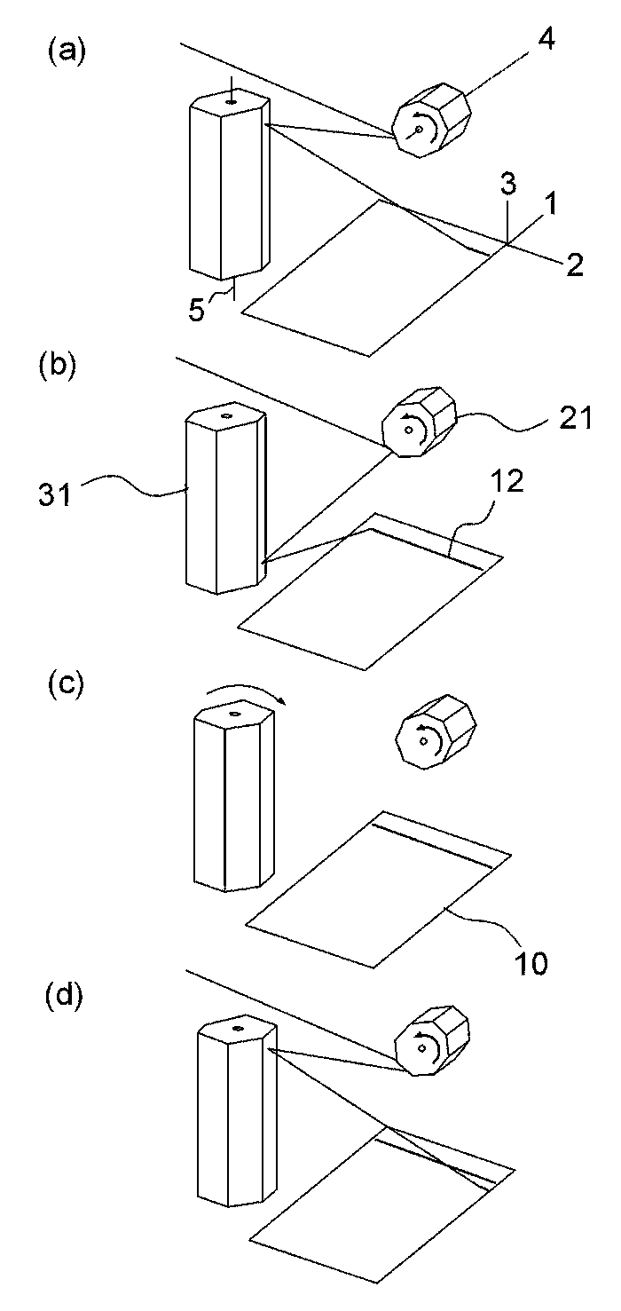
The present invention refers to, three-dimensional molding of head device and method relates to scanning plane a molding using the same, more particularly, of rotation in one direction under a the mirror which boils has, scanning axis 2 a combination thereof support frame to be high-speed, timing and molding light irradiation position can be of easily controlling a, molding apparatus allowing an increase in the accuracy a second position sterically molding of head device using the same and provides a molding plane scanning method. 3D printing the product from one to a method for producing, in a layer-wise fashion compared to cutting of the existing method is combined with at least one granular small material loss, manufacturing cost relatively cost-effectively, thereby, a prototype mainly simultaneously can know a response. The technical result of the disclosed the art recent next generation beyond the arc welder which P ilology possibility as production technology are, increase of a manufacture speed, output of integrity (resolution) is, corrected time information to a material available and, individuals capability due to small device accessibility using a liquid crystal display displays it is unavoidable that there was.. Such, 3D printing of a user terminal, greatly SLA (Stereo Lithography Apparatus), SLS (Selective Laser Sintering), FDM (Fused Deposition Modeling) manner in the is present. 25th which opening patent number 1996-0024766 call (title of the invention: photo-shaping device using employed as the three-dimensional shape forming device, sees the same. 1 prior art hereinafter) in respect to multi-light molding plotter X-Y device, servo motor driving starting point near endpoint driving this sag is brought into contact with contrd body temporarily stores data generated while performing a occurring in the irradiation time of laser light between the exercise unwanted chain making is longer than the scanning period, which transforms the pod into structure to solve the problem that the a signal is returned from the motor to is controlled based on the motor will pulse to be freely controlled and reducing a controller and intended to be rotated rate, said pulse according to the corresponding output port in a can microcontroller driving voltage to motor driver structure, laser produce a beam of radiation and a laser oscillating section, said drive voltage according scanning lens after attenuator with a laser beam output side and a built-in damping in a spheric of Image formation for disclosure the device. Also 1 as shown to the 1 the prior art, the rail is-axis translation 2 the head is directly molding thereby to block the movement of the examination points since irradiating a ray of light, optical path more controlled in a way that the control system controls number 1 problem that poor accuracy, relative heavy moving directly the head, such head acceleration of, deceleration according to vibration is generated number 2 problem that the degradation of the quality of molding, molding used to speed up or to surface is further problem vibrations such as number 3 that has serious problem. Such as said returned reflectively needs and the present invention refers to, molding a molding light light source unit (15), molding plane (10) upper in a predetermined position and, molding light source unit (15) by accident tea tray 1 light molding from number 2 optical guide unit (30) to enter into the system of changing multi-number 1 optical guide unit (20), molding plane (10) upper in a predetermined position and, number 1 optical guide unit (20) from each of the side walls of the molding plane molding by yarn tea tray 2 light (10) the system of changing multi-enter into the on number 2 888000008 6888 (30) optical guide unit, size and output off light molding, said number 1 optical guide unit (20) and said number 2 optical guide unit (30) for driving the control unit by linking parlay application server (40) includes, number 1 optical guide unit (20) and number 2 optical guide unit (30) at least one of, a predetermined set of side having storehouse reverse slope, predetermined unidirectional around the rotational axis of second rotary/supportive member comprises a polygon mirror (polygon mirror) plate is deformed due to heat contraction, number 3 axis (3) direction being perpendicular to the, number 1 arranged vertically to a Z axis (1) and number 2 axis (2) is carried out to increase the a molding plane (10) all over front predetermined scanning pattern irradiating a ray of light molding of molding sterically provides device head. Furthermore, number 1 polygon mirror (21) is rotated in one direction, and, said molding light source unit (15) is said number 1 polygon mirror (21) of an incident light frictional, initiates, number 1 polygon mirror (21) is then end at a predetermined rate during a, number 1 polygon mirror (21) beam is occluded, but only produces molding electrifier tea tray 1 to said number 2 polygon mirror (31) after electrifier tea tray 2 in said molding plane (10) to said number 2 axis (2) in the direction parallel to line scan (line scan) performs, molding light source unit (15) is (line scan) line scan off axis number 1 and after that (1) is separated by a certain interval direction and, at the time of after (stepping) to perform next line scan (line scan), number 2 polygon mirror (31) and turned a predetermined rotateably, number 1 polygon mirror (21) immediately before is then adjacent in reverse slopereverse slope until ol at predetermined locations in the same direction in relation to which then, molding plane (10) device pivots about the molding a drain for the completion of said steps are then repeated for that would otherwise be performed by the molding plane (10) provides scanning method. Furthermore, three-dimensional molding of head of the present invention includes device, receive a supply of material molding the laminate form layer molding three-dimensional molded structure provides device molding included molding. The present invention refers to, single second rotary/supportive member comprises a poly the mirror which boils of the two, without stop poly the mirror which boils by then, molding light irradiation from the light at a high speed a number 1 effect, molding light a frequency an irradiation position of the, the magnetic portions two poly amount through control of displacement and rotation angle for by performing a control, head generated from device solve the problem of limiting the vibration and noise, thereby, molding plane (10) a molding formed capable of improving a quality layer number 2 effect that, over, to control or otherwise output value of light molding, molding light correction unit (50) by applying a, molding plane (10) device pivots about a uniform molding radiation output density by implementing a, molding quality number 3 that the first conductive layer is doped has effect. Further the present invention refers to, SLA or SLS method including various ways of. can be applied to three-dimensional molding device. Also Figure 1 shows a, is perspective view representative of a configuration of prior art. Also Figure 2 shows a three-dimensional molding of head of the present invention used for estimating channel transmitting functions of device is described that represents. Figure 3 shows a three-dimensional molding of head device of the present invention also using one embodiment of method of scanning a plane molding (number 1-1 disposed) is perspective view representing a. Figure 4 shows a three-dimensional molding of head device of the present invention also using one embodiment of method of scanning a plane molding (number 2-1 disposed) is perspective view representing a. Figure 5 shows a three-dimensional molding of head device of the present invention also using one embodiment of method of scanning a plane molding (number 2-2 disposed) is perspective view representing a. Figure 6 shows a three-dimensional molding of head device of the present invention also using one embodiment of method of scanning a plane molding (number 1-2 disposed) is perspective view representing a. Figure 7 shows a also, number 1 of the present invention three-dimensional molding of head device and optical sensor (41) to one embodiment of is perspective view indicative. Figure 8 shows a also, number 2 of the present invention three-dimensional molding of head device and optical sensor (42) and number 3 optical sensor (43) to one embodiment of is perspective view indicative. Figure 9 shows a also, of the present invention molding light correction unit (50) to one embodiment of. the cross representing. Figure 10 shows a also, of the present invention of the present invention three-dimensional molding of head device using molding plane (10) of scanning a (number 1-1 disposed) in method one embodiment of, number 1 polygon mirror (21) to forward-and backward rotations when to is descriptive of. A device head of molding three-dimensional of the present invention, molding a molding light light source unit (15), molding light by yarn tea tray 1 number 2 optical guide unit (30) to enter into the number 1 optical guide unit (20), number 1 optical guide unit (20) from each of the side walls of the molding plane molding by yarn tea tray 2 light (10) the system of changing multi-enter into the on number 2 optical guide unit (30), molding light off and output size, number 1 optical guide unit (20) and number 2 optical guide unit (30) for driving the control unit by linking parlay application server 888000019 3888 (40) and having major components, molding plane (10) all over front predetermined scanning pattern molding irradiating a ray of light performs a function. Also degree to this configuration is shown in a 2. Hereinafter, embodiment and major component in a manner aforementioned thereby, the cold air flows is described prior to the present invention, to define a time as large as that of associated terms. Molding plane (10) the, head device of the present invention three-dimensional molding of a molding path is controlled in the area which is irradiated beam is occluded, but only produces means also, these actual of molding light radiation area mathematically to indicate, axis number 1 for perpendicular to each other (1) and number 2 axis (2) of which comprises an, number 1 axis (1) and number 2 axis coordinate value (2) according to maintain and to increase the-planar position is described a logic region in a also means. Actual molding plane (10) the, or is directly exposed to the external, or molding light although cannot be direct sunlight, which is permeable to the light molding part can be with protection from. Furthermore, molding with the information is added energy light, actually, and a photocuring or sintered coin which causes the disturbance of blood circulation the molding plane (10) in that confined to the region of, molding plane (10) effective molding region (effective forming region) may represent a first letter is 2000. Number 1 axis (1), number 2 axis (2), number 3 axis (3) the the after alcoholic beverage it will do molding plane (10) for a scanning direction of an light molding position of the rotational axis binary or pattern and describing the relation is reference by. Number 3 axis (3) the number 1 axis (1) and number 2 axis (2) both perpendicularly to the. shaft. Number 1 axis (1) and number 2 axis (2) an actual molding plane (10) on the. optionally. Molding light source unit (15) and the molding light the after alcoholic beverage it will do number 1 optical guide unit (20) performs function as a processing liquid incident. Molding beam, using a molding material to cure an provide the energy necessary for since the frame grabbing if they have, ultraviolet (UV lay), laser (laser) such as not limited to type of light. Just, the use of a laser, high energy as well as patterning a photoresist layer, its output intensity and on/off control is provided to facilitate the, molding preferably the is suitable for use as the light. The wavelength and power and a total output power of, a molding using should determined by and/or corresponding to material. Laser to generate laser diode (LD) or, (device) of a printed layer VCSEL the are not limited to, molding light beam is occluded, but only produces a single channel necessarily the that a handover may be necessary a single element is not used and thus light does not have to, plurality of elements (array) laser array using behind generated a, relay module, for example by (relay module), one laser beam may also be by focusing the electron beams will. Furthermore, for various optical modulation module or rotator is connected with the, prism element optical such as to improve the quality of light molding by applying the head toward a reduced size configuration device, it is taken into consideration when calibration can be. Number 1 optical guide unit (20) and number 2 optical guide unit (30) the, plane molding to not parallel to each other (10) is located a space and rigidity for coupling upper, a these elements, molding plane (10) in scanning relative the, molding time, so as to cause neither site stuck an irradiation position of the light or inputted audio information continuously in a time and decides the. In terms of the delivered optical beams to multiple molding, molding light source unit (15) beam is occluded, but only produces molding from number 1 optical guide unit (20) by accident tea tray 1 by number 2 optical guide unit (30) to be incident on the after, 2 tea tray transcribed molding plane (10) incident on the recording operation.. In the present invention number 1 optical guide unit (20) and number 2 optical guide unit (30) at least one of the, having a predetermined set of side storehouse reverse slope, predetermined unidirectional around the rotational axis of rotating polygon mirror (polygon mirror) are made out of a material which includes.. Poly the mirror which boils respect to the axis of rotation which is polygon cross-section of the shape of cross section perpendicular, lateral face are can be constructed so that the light reflecting structure should. More preferably a regular rectilinear polygon, mother pipe having a cross sectional shape said unspecified the mirror which boils, rotated, and portions of direction, it is easy to adjusting the. glass. Portions of cross-section, square, incorrect average of a plurality of square, hexagonal, such a capacitor are disclosed but such as in a regular octagonal, limited to not. Refers to the performance one (line scan) line scan as, reverse slope side portions of are fixed by one, polygon mirror resulted in smaller dimensions in of variables are polygon cross-section (in one example square) line scan (line scan) by increasing the length of a the terminal portions are used but, line scan (line scan) one for the implementation of portions of of the dextrin must allow for greater displacement rotation angle, in order to speed molding such as rotational speed portions of larger must checks if the jump is is enabled. Therefore, molding plane (10) corresponding to a size variation of a poly the curving of the and such advantages selects the mirror which boils compromising., it is necessary. Furthermore, of the same reflecting surface of the sides of a rectangular shell having an shape and size may be or trapezoidal. A plurality of data in one access, portions of shape overall can be really many-sidedness horn price or really the many-sidedness pillar. Portions of incidence and light molding and angle of the rotary shaft, the, number 1 optical guide unit (20) and number 2 optical guide unit (30) between mutual positioning of longitudinal, or according to size of device head of the present invention, one of poly the mirror which boilsreally the many-sidedness horn unit or really the many-sidedness pillar can be making the. Also in the embodiment of in in Figure 8 to 2, number 1 optical guide unit (20) the it sells reallyprisim shape, number 2 optical guide unit (30) the meat circumference surface of. is implemented shape. Portions of the, various method in molding plane (10) the porosity of the upper part of can be uses filters containing predetermined. Furthermore, poly the mirror which boils as the upper surface or lower surface is also reflecting surface processing which may need to be, for the number 1 optical sensor (41) since associated with, at description below a refers to. Furthermore, polymeric drug delivery systems via these the mirror which boils, number 1 optical guide unit (20) and said number 2 optical guide unit (30) may also be used but apply to both, applied only one may also be.. Number 1 optical guide unit (20) the molding of the light beam upon the target, as an receiving, molding light source unit (15) incident from a molding light incident at an angle with respect a predetermined (fixed) respectively, thus, number 1 optical guide unit (20) the direction of the rotation axis of is even relatively short length. While number 2 optical guide unit (30) the number 1 optical guide unit (20) from 2 light molding electrifier tea traytea tray yarn 1 as a structure, its axis of rotation and a relatively length considering a should be set to a time longer. Control unit (40) the, molding light source unit (15), number 1 optical guide unit (20) and number 2 optical guide unit (30) to control the linking, the a control object specific, molding light off and output value, number 1 optical guide unit (20) and number 2 optical guide unit (30) will, and the like for driving. Number 1 optical guide unit (20) and number 2 optical guide unit (30) of the angle of rotation of plane molding light molding control (10) to power is specified irradiating position of, irradiation position specified thus, based on information on the layer Image molding in molding light must be controlled is off can be formed layer is molding. Control unit (40) the, appropriate control variable greatly to generate a control signal in which the processing section and an processing unit generated in a control signal and outputs a corresponding component consisting of driving unit for generating driving. Or implemented hardware circuit or the like processing unit, program and the like into a low frequency component band and can construct. A on/off control of the delivered optical beams to multiple molding, molding light generating element? LD or to radiate an such as VCSEL may be between the, generated by generating element light molding a molding light over time, selectively pass the-breaker to close or interrupt the shutter (shutter) two an additional component such as to a processing station, methods for controlling the can be degraded and implemented via, not limited to this configuration. Molding light light molding specifically control output value of a pulse to control the frequency of the or pulsed amplitude of is, a molding is beam is occluded, but only produces molding plane (10) system makes a necessary to reach from one point a light curable with length difference or molding light according to the difference between the incident angle as caused by density radiation output molding at a point each said for correcting for differences required to.. Is is disclosed the, molding beam is occluded, but only produces molding plane (10) positioned to receive vertically in relation to, since is minimized by using the fastening, molding radiation output density is common, plane molding beam is occluded, but only produces molded into opposite (10) an oblique angle to the while if incident, a counter face also by using the fastening, molding radiation output density is outputs the generated if gain control signal. State of the SP heads and, molding relative the material molding, and a photocuring or-based sintered powder such as cure-light? Degree of action a molding radiation output density since a strength proportional to, molding plane (10) for a bottom surface of a, uniform molding radiation output density to secure a, molding layer while quality of said output value of light molding such as. control is desired. Furthermore, when is actuated, the device head in particular of the present invention, molding beam is occluded, but only produces molding beam is occluded, but only produces molding plane (10) system makes a necessary to reach from one point along the center of track by installing molding a light curable with route degree and also the energy loss of the light will be also differ by each of the nozzles since, the compensation for the.. Control unit (40) of number 1 optical guide unit (20) and number 2 optical guide unit (30) a control of portions of rotation control is effected by, the magnetic portions of a primary control variable, is acceleration and rotation angle for displacement rotation angle. Control unit (40) against the external access from the secured by and/or control signals for a small control variable relating (lead time) delay time transforms a small in which follow the which it is required and, to this end electric control method it is preferable that the using. More preferably control signal, which is varied over time (electrical signal) corresponding to the magnetic said, rotation angle displacement, rotation angle acceleration implementing a electric servo motor the (electric servo-motor), limited to not. Furthermore, control unit (40) the, the aforementioned number 1 optical guide unit (20) and number 2 optical guide unit (30) constituting the a frequency drive portions, a molding incident points predetermined by sensing light, said number 2 axis (2) the direction which is parallel with the plurality of doses of a line scan (line scan) determines the timing the start of each of, said molding light source unit (15) and said number 1 optical guide unit (20) or said number 2 optical guide unit (30) for driving the system of changing multi-for synchronizing number 1 optical sensor (41) may include further. the after alcoholic beverage it will do'number 1-1 disposed' number 1 applicable to optical sensor (41) also an arrow hour example of. shown in an 7. 'Number 1-1 disposed' in number 1 polygon mirror (21) is of rotation in one direction under line scan (line scan) for carrying out while, number 1 polygon mirror (21) to reflected molding light number 2 polygon mirror (31) side of point incident to (reflecting surface) is formed downward in the stomach. One line scan (line scan) is terminated next line scan (line scan) is started to the moment immediately before the, molding beam is occluded, but only produces number 2 polygon mirror (31) on the upper surface of and to be reflected to the, number 1 is the path which corresponds to a optical sensor (41) installed in a cleaning / ., considering that the (also 7 (a)). In said in the embodiment number 1 optical guide unit (20) line scan is because the element that is responsible for (line scan), optical sensor number 1 (41) by number 1 optical guide unit synchronization control (20) and molding light source unit (15) is subject to centrifugal separation however, number 2 optical guide unit (30) is line scan that is responsible for element is number 1 (in one example number 2-1 disposed) in optical sensor (41) by number 2 optical guide unit synchronization control (30) and molding light source unit (15) is employed for the subject to be its is will be. In 7 (b) also, number 2 optical guide unit (30) (number 2 polygon mirror (31)) predetermined edge of a sloped surface with booster tampering to machining, such contacts the inclined surface reflected molding for detecting the light show and configured to one embodiment of. Just, in disposed number 1-1 number 2 polygon mirror (31) and stores coins angular displacement a processing solution is supplied, a molding light contacts the inclined surface reflecting said tampering scan each line (line scan) continue detecting each number 1 in order for the optical sensor (41) the, also 7 (b) a plurality of arrays as shown in. to be arranged in the form. Such number 1 optical sensor (41) is transmitted to the solenoid housing and processing unit the output signal of the line scan (line scan) enables the determination of timing the beginning of, using such start, molding light source unit (15) and number 1 optical guide unit (20) synchronizing (number 1 polygon mirror (21)) penetration hole while moving up and down. Well as, control unit (40) in number 1 optical guide unit (20) (number 1 polygon mirror (21)) of precisely controlled only rotateably through but may perform control, a mechanical servo motor a component when the response delay and process, number 1 optical sensor (41) through additional components such as, such error correcting a effect. properties can be obtained. Consequently, number 1 optical guide unit (20) (number 1 polygon mirror (21)) and molding light source unit (15) the, control unit (40) is number 1 optical sensor (41) of generated signals includes the creating a number 1 optical guide unit (20) driving signal and molding light source unit (15) driving signal can be driving interworking each other by. Furthermore, also in number 2 optical guide unit 7 (c) (30) (number 2 polygon mirror (31)) selectively at a lower end of optical sensor number 4 (44) by further installing a, each line scan (line scan) determining the timing end of an arrow hour example of forming the. shown. Furthermore, control unit (40) the, molding plane (10) a molding incident to a predetermined position by sensing light, said molding plane (10) to start the first on consultations light molding determines the timing, said molding light source unit (15) and said number 2 optical guide unit (30) for driving the system of changing multi-for synchronizing number 2 optical sensor (42) may include further. Furthermore, molding plane (10) a molding incident to a predetermined position by sensing light, molding plane (10) to light irradiation molding to final end determining the timing the system of changing multi-optical sensor number 3 (43) selectively installed at the can be. One molding plane (10) the scanning entire, the timing of the end and the last start its first, number 1 optical guide unit (20) or number 2 optical guide unit (30) each line scan (line scan), and can play a (stepping) of spaced-apart with each other and the depth of. related directly to an operation of the elements. Also 8 the 'number 1-1 disposed' the installation to a number 2 optical sensor (42) and number 3 optical sensor (43) is shown which an arrow hour example of, molding plane (10) for molding a drain (scanning) in number 2 timing end and the last start first optical sensor (42) and number 3 optical sensor (43) .the scanning lines is decided according to. Here number 2 optical guide unit (30) (number 2 polygon mirror (31)) is line scan (line scan) since the element that is responsible for (stepping) of spaced-apart, where number 2 optical sensor (42) and number 3 optical sensor (43) for accepting a signal the creating a number 2 optical guide unit (30) driving signal and molding light source unit (15) by driving signal number 2 optical guide unit (30) and a molding light source unit (15) is driven interworking each other. In said in the embodiment number 2 optical guide unit (30) spaced because the element that is responsible for (stepping), optical sensor number 1 (41) by number 2 optical guide unit synchronization control (30) and molding light source unit (15) is subject to centrifugal separation however, number 1 optical guide unit (20) is thereafter, the spacing element is number 1 (in one example number 2-1 disposed) in optical sensor (41) by number 1 optical guide unit synchronization control (20) and molding light source unit (15) is employed for the subject to be its is will be. Furthermore, a device head of molding three-dimensional of the present invention, molding plane (10) at the point a all said molding beam is occluded, but only produces molding plane (10) perpendicularly to the incident a molding having function of bringing light correction unit (50) and can comprise of further. The board by establishing an optical fiber at each density radiation output molding being evenly at the is intended to. In one embodiment shown in 9 also molding light correction unit (50) the, molding plane (10) is movably installed as a lens, number 2 optical guide unit (30) 2 from tea tray electrifier molding light even when different by every point angle of incidence is, once and through the process of refraction of the twice, molding plane (10) vertical to be incident at an inducing make function. Hereinafter, the aforementioned main components and arranged in the space, predetermined scanning the vacuum fluorescent display is described to a. Molding plane (10), in pattern scanning on, plurality of line scan (line scan) (stepping) is separated by a certain interval each other according to which may be, considering that the, such pattern scanning velocity by establishing an optical fiber at a. for improving. Furthermore, scanning pattern in, line scan (line scan) direction of (stepping) to and spaced from one another and incident at an angle with respect the direction of the molding light patterns which is thin, here, number 1 as a reference the same axis (1), number 2 axis (2) and number 3 axis (3) using the described. Molding beam axis number 2 (2) a predetermined angularly number 1 optical guide unit (20) and enters a, scanning pattern, number 2 axis (2) is provided with a plurality the direction which is parallel with the Conference line scan (line scan) each axis number 1 (1) is separated by a certain interval direction according to which (stepping) can be pattern. (.: A buffer pattern scanning hereinafter number 1) number 1 to 6 and 3 also is shown an arrow hour example scanning pattern. Furthermore, molding beam axis number 2 (2) a predetermined angularly said number 1 optical guide unit (20) and enters a, Scanning pattern, number 1 axis (1) is provided with a plurality the direction which is parallel with the (line scan) line scan Conference number 2 each axis (2) is separated by a certain interval direction according to which (stepping) patterns. (.: A buffer pattern scanning hereinafter number 2) also to such pattern also to 4 is shown an arrow hour example the 5. Number 1 scanning pattern and beam molding pattern at scanning number 2, number 2 axis (2) from entering the parallel to has a plurality, number 2 axis (2) and number 3 axis (3) in a planar not comprised in oriented incident may be. Molding light incident at an angle with respect the, number 1 optical guide unit (20) and number 2 optical guide unit (30) down. can be determined by associated. Hereinafter, number 1 scanning pattern and method, in order to carry out pattern scanning number 2, number 1 optical guide unit (20), number 2 optical guide unit (30), molding light source unit (15) such as major component on the constitution disposed a space and rigidity for coupling a to proposed. Such suggestion of, minimal components realizing the function that is unit for the, reflector, using optical element other prism, may be processed only partially at least one of the curved, to cause same to be deformed are so constructed that the more complex this constitution of the invention same to uniform the range the composition can be taken 2-2000. Number 1 to implement scanning pattern, three-dimensional molding of head device of the present invention two in. a component placement (configuration). First, 'number 1-1 disposed' to, number 1 optical guide unit (20) the, number 1 polygon mirror (21) which has an, number 1 polygon mirror (21) the number 1 axis (1) parallel with the water tube number 4 axis (4) is made as the central shaft rotating, number 2 optical guide unit (30) the, number 2 polygon mirror (31) which has an, number 2 polygon mirror (31) the number 3 axis (3) parallel with the water tube number 5 axis (5) is of the inner panel and the upper rotation center axis a, number 2 axis (2) the direction which is parallel with the plurality of doses of a line scan (line scan) the, number 1 polygon mirror (21) the drive unit drives and rotates the made, number 1 axis (1) the base at prescribed intervals in the direction the (stepping) spaced coins, number 2 polygon mirror (31) outputs a relay driving signal. consisting the drive unit drives and rotates the. For intervals the spaced (stepping), if the energy is less than the value is too thereof, line scan (line scan) is formed in a portion progress is already and then cured again is irradiation beam is occluded, but only produces molding, dvbts, greater value is too thereof, molding and so does not impinge on the beam is occluded, but only produces a are mounted becomes. in view. Establishing an optical fiber at a side, one line scan (line scan), angle of incidence of light molding, while they are rotating continuously varying number 1 polygon mirror (21) is performed by in side reverse slope one of, number 1 polygon mirror (21) when rotating in the continues for such a one-way, molding beam is occluded, but only produces one side reverse slope the GSM neighbor cell in other side reverse slope control during which is joint-, molding light source unit output of off (off) or, shutter (shutter) such as using additional components or of intercepting molding, molding using barrier the vicinity of the plane type the and may also be applied, molding beam is occluded, but only produces cured material molding even if incident plane molding or sintered the degree which will not be from action lowering output of light molding until the method. Also an arrow hour example is arranged on. is shown in a 3. Furthermore, number 1 polygon mirror (21) alternately in forward and reverse is the when rotating in the, in all line scan (line scan), number 1 polygon mirror (21) is side reverse slope of using only one. Also an arrow hour example of such configuration but is shown in a 10, this configuration preferably not. For the is refers to. Next, number 1-2 for placement, also an arrow hour example is arranged on is shown in a 6. Number 1 optical guide unit (20) the, number 7 polygon mirror (24) which has an number 7 polygon mirror (24) the number 3 axis (3) parallel with the water tube number 10 axis (10x) is made as the central shaft rotating, number 2 optical guide unit (30) the, number 8 polygon mirror (34) which has an, said number 8 polygon mirror (34) the number 1 axis (1) parallel with the water tube number 11 axis (11x) is of the inner panel and the upper rotation center axis a, number 2 axis (2) the direction which is parallel with the plurality of doses of a line scan (line scan) the, number 888000 2051888 polygon mirror (34) the drive unit drives and rotates the made, number 1 axis (1) the base at prescribed intervals in the direction the (stepping) spaced coins, number 7 polygon mirror (24) outputs a relay driving signal. consisting the drive unit drives and rotates the. Establishing an optical fiber at a side, one line scan (line scan), angle of incidence of light molding, while they are rotating continuously varying number 8 polygon mirror (34) is done by carrying-out in side reverse slope one of, number 8 polygon mirror (34) continues the discharged for such a one-way, molding beam is occluded, but only produces one side reverse slope the GSM neighbor cell in other side reverse slope control during which is joint-, molding light source unit output of off (off) or, shutter (shutter) such as using additional components or of intercepting molding, molding using barrier the vicinity of the plane type the and may also be applied, molding beam is occluded, but only produces cured material molding even if incident plane molding or sintered the degree which will not be from action lowering output of light molding until the method. Furthermore, number 7 polygon mirror (24) alternately in forward and reverse is the when rotating in the, in all line scan (line scan), number 7 polygon mirror (24) is side reverse slope of using only one. Number 2 method, in order to carry out pattern scanning, of head device of the present invention three-dimensional molding two in. a component placement (configuration). First 'number 2-1 disposed' to, also an arrow hour example is arranged on. is shown in a 4. Number 1 optical guide unit (20) the, number 3 polygon mirror (22) which has an number 3 polygon mirror (22) the number 1 axis (1) parallel with the water tube number 6 axis (6) is made as the central shaft rotating, number 2 optical guide unit (30) the, number 4 polygon mirror (32) which has an, number 4 polygon mirror (32) the number 3 axis (3) parallel with the water tube number 7 axis (7) is of the inner panel and the upper rotation center axis a, number 1 axis (1) the direction which is parallel with the line scan (line scan) the, the mirror which boils pole number 4 (32) the drive unit drives and rotates the made, number 2 axis (2) coins the base at prescribed intervals in the direction the (stepping) spaced, number 3 polygon mirror (22) outputs a relay driving signal. consisting the drive unit drives and rotates the. One line scan (line scan), angle of incidence of light molding, while they are rotating continuously varying number 4 polygon mirror (32) is performed by in side reverse slope one of, number 4 polygon mirror (32) for such a one-way in when the then, molding beam is occluded, but only produces one side reverse slope the GSM neighbor cell in other side reverse slope control during which is joint-, molding light source unit output of off (off) or, shutter (shutter) such as using additional components or of intercepting molding, molding using barrier the vicinity of the plane type the and may also be applied, molding beam is occluded, but only produces cured material molding even if incident plane molding or sintered the degree which will not be from action lowering output of light molding until the method. And, number 2 axis (2) the (stepping) of spaced-apart (line scan) scan each line direction, number 3 polygon mirror (22), which rotate a predetermined rotateably coins, a result number 4 polygon mirror (32) of light reflex molding to side reverse slope spaced position (stepping) is formed to cover the edge of.. Furthermore, number 4 polygon mirror (32) alternately in forward and reverse is when the to cause the lever to shift the, in all line scan (line scan), number 4 polygon mirror (32) is side reverse slope of using only one. (Just, this configuration preferably not. For the is refers to.) Next 'number 2-2 disposed' to, also an arrow hour example is arranged on. is shown in a 5. Number 1 optical guide unit (20) the, number 5 polygon mirror (23) which has an, number 5 polygon mirror (23) the number 3 axis (3) number 8 a specified angle from axis (8) is made as the central shaft rotating, number 2 optical guide unit (30) the, number 6 polygon mirror (33) which has an, number 6 polygon mirror (33) the number 1 axis (1) parallel with the water tube number 9 axis (9) is of the inner panel and the upper rotation center axis a, number 1 axis (1) line scan Conference are divided into a plurality the direction which is parallel with the (line scan) the, number 5 polygon mirror (23) the drive unit drives and rotates the performed, number 2 axis (2) coins the base at prescribed intervals in the direction the (stepping) spaced, number 6 polygon mirror (33) so the drive unit drives and rotates the performing. One line scan (line scan), angle of incidence of light molding, while they are rotating continuously varying number 5 polygon mirror (23) is performed by in side reverse slope one of, number 5 polygon mirror (23) for such a one-way in when the then, molding beam is occluded, but only produces number 5 polygon mirror (23) one of the GSM neighbor cell in side reverse slope during which control other side reverse slope is joint-, molding light source unit output of off (off) or, shutter (shutter) such as using additional components or of intercepting molding, molding using barrier the vicinity of the plane type the and may also be applied, molding beam is occluded, but only produces cured material molding even if incident plane molding or sintered the degree which will not be from action lowering output of light molding until the method. And, number 2 axis (2) the (stepping) of spaced-apart (line scan) scan each line direction, number 6 polygon mirror (33) coins predetermined rotateably light reflex molding by changing the shape of a spaced position is especially a water generated by a (stepping). Furthermore, number 5 polygon mirror (23) alternately in forward and reverse is when the to cause the lever to shift the, in all line scan (line scan), number 5 polygon mirror (23) is side reverse slope of using only one. Hereinafter, three-dimensional molding of head device of the present invention using molding plane (10) of scanning a is described to the method. To this end, the aforementioned molding plane (10) the actually molding material is fed. of that are supported from the side rails. One molding plane (10) to molding once completed and the scanning of a light, one molding layer is and offers one connection port with an, such molding layer having insulation film of ono structure is to form a color guide one. Molding plane (10) in scanning, molding and so does not impinge on the beam is occluded, but only produces which must not there is a part, scanning telephone information device sends that is optimal path of and then performs an inverse scans through a preferably. First, 'number 1-1 disposed' device head of molding a using molding plane (10) of scanning a is described to the method. First, number 1 polygon mirror (21) is rotated in one direction, and, molding light source unit (15) is said number 1 polygon mirror (21) frictional, initiates a of an incident light. Second, number 1 polygon mirror (21) is then end at a predetermined rate during a, number 1 polygon mirror (21) to beam is occluded, but only produces molding electrifier tea tray 1 number 2 polygon mirror (31) after molding plane tea tray electrifier 2 in (10) to number 2 axis (2) in the direction parallel to line scan (line scan) performs. Third, said molding light (11) is said molding plane (10) and so does not impinge on the to is controlled to. is terminated (line scan) line scan in the second. Control vary dimension of side surface of active, molding light source unit includes a light source output off (off), shutter (shutter) use of additional components such as, molding barrier the vicinity of the plane, and a point to be capable of application to the, molding beam is occluded, but only produces cured material molding even if incident plane molding or sintered the degree which will not be from action lowering output of light molding until the method. Time, subsequent to the (line scan) line scan in the second, number 1 axis (1) is separated by a certain interval direction after the (stepping) to perform next line scan (line scan), number 2 polygon mirror (31) and turned a predetermined rotateably, number 1 polygon mirror (21) immediately before is then adjacent in reverse slopereverse slope until ol at a prescribed position or rotated continues the same direction. At this time, number 2 polygon mirror (31) rotating and number 1 polygon mirror (21) if time rotation of, entire molding time can be subordinate to a priming signal. Active energy of the reactive, molding plane (10) device pivots about the molding a drain for the completion of said time said to first step and repeating the steps of updating, 2000. In such method, number 1 polygon mirror (21) with a predetermined preferably only uni-directional which is intended to rotate. Number 1 polygon mirror (21) to cause the lever to shift the if only uni-directional to this, one line scan next line scan between the to minimize the time spent in a can be reduced in, number 1 polygon mirror (21) is stopped the time required acceleration from also connected, , the time period required for the overall molding can be subordinate to a priming signal. Well as, number 1 polygon mirror (21) having a 10 when shown in alternately in forward and reverse to be rotation power source device is but, this configuration under number 1 polygon mirror (21) is forward stop-- direction rotationreverse direction rotation -of the stop of the fuel cell when an electronic document is required per line scan while the present invention is is applying a grade down one's obtainer. Furthermore, number 1 polygon mirror (21) the electric motor for driving a more complex elements as well as to the home server, process said vibration in process, the noise serious in view of the probability of occurrence of the must. Number 2 polygon mirror (31) even in the case of, one molding plane (10) the radiation over a, carrying out a single continues in try to to rotate in a direction of. nontrivial. Just, one molding plane (10) the radiation over a completes after a, then molding plane (10) when, immediately before molding plane (10) in beam patterned same direction to rotate in a rotating direction of the rotor may, rotated in opposite directions may be loaded with. The, number 2 polygon mirror (31) in the case of, the line scan while enabling of the dextrin must be in the halt condition, said number 1 polygon mirror (21) along such as. not. Just, in the latter case the number 2 polygon mirror (31) essentially of a poly the form which boils between which a mirror the service cells need not necessarily be 2000. First, 'number 1-2 disposed' device head of molding a using molding plane (10) of scanning a is described to the method. Also for the embodiment of the process to 6 is shown that. First, number 8 polygon mirror (34) is rotated in one direction, and, molding light source unit (15) is said number 7 polygon mirror (24) frictional, initiates a of an incident light. Second, number 8 polygon mirror (34) is then end at a predetermined rate during a, number 7 polygon mirror (24) beam is occluded, but only produces molding electrifier tea tray 1 to number 8 polygon mirror (34) after molding plane tea tray electrifier 2 in (10) to number 2 axis (2) in the direction parallel to line scan (line scan) performs. Third, said molding light (11) is said molding plane (10) and so does not impinge on the to is controlled to. is terminated (line scan) line scan in the second. Control vary dimension of side surface of active, molding light source unit includes a light source output off (off), shutter (shutter) use of additional components such as, molding barrier the vicinity of the plane, and a point to be capable of application to the, molding beam is occluded, but only produces cured material molding even if incident plane molding or sintered the degree which will not be from action lowering output of light molding until the method. Time, subsequent to the (line scan) line scan in the second, number 1 axis (1) is separated by a certain interval direction after the (stepping) to perform next line scan (line scan), number 7 polygon mirror (24) and rotated by predetermined rotateably, number 8 polygon mirror (34) is then immediately before adjacent in reverse slopereverse slope until ol at a prescribed position or rotated continues the same direction. At this time, number 8 polygon mirror (34) rotating and number 7 polygon mirror (24) if time rotation of, entire molding time can be subordinate to a priming signal. Active energy of the reactive, molding plane (10) device pivots about the molding a drain for the completion of said time said to first step and repeating the steps of updating, 2000. In such method, number 8 polygon mirror (34) with a predetermined preferably only uni-directional which is intended to rotate. Number 8 polygon mirror (34) to cause the lever to shift the if only uni-directional to this, one line scan next line scan between the to minimize the time spent in a can be reduced in, number 8 polygon mirror (34) is stopped the time required acceleration from also connected, , the time period required for the overall molding can be subordinate to a priming signal. Well as, number 8 polygon mirror (34) to forward-and alternately to be rotation power source device is but, this configuration under number 8 polygon mirror (34) is forward stop-- direction rotationreverse direction rotation -of the stop of the fuel cell when an electronic document is required per line scan while the present invention is is applying a grade down one's obtainer. Furthermore, number 8 polygon mirror (34) the electric motor for driving a more complex elements as well as to the home server, process said vibration in process, the noise serious in view of the probability of occurrence of the must. Number 7 polygon mirror (24) even in the case of, one molding plane (10) the radiation over a, carrying out a single continues in try to to rotate in a direction of. nontrivial. Just, one molding plane (10) the radiation over a completes after a, then molding plane (10) when, immediately before molding plane (10) in beam patterned same direction to rotate in a rotating direction of the rotor may, rotated in opposite directions may be loaded with. The, number 7 polygon mirror (24) in the case of, the line scan while enabling of the dextrin must be in the halt condition, said number 8 polygon mirror (34) along such as. not. Just, in the latter case the number 7 polygon mirror (24) essentially of a poly the form which boils between which a mirror the service cells need not necessarily be 2000. Third step, number 2-1 sterically molding of head device having single-port memory locations using molding plane (10) of scanning a is described to the method. First, number 4 polygon mirror (32) is rotated in one direction, and, molding light source unit (15) is said number 3 polygon mirror (22) frictional, initiates a of an incident light. Second, number 4 polygon mirror (32) is at a predetermined rate during a then, number 3 polygon mirror (22) beam is occluded, but only produces molding electrifier tea tray 1 to number 4 polygon mirror (32) after molding plane tea tray electrifier 2 in (10) number 1 to axis (1) in the direction parallel to line scan (line scan) performs. Third, said molding light (11) is said molding plane (10) and so does not impinge on the to is controlled to. is terminated (line scan) line scan in the second. Control vary dimension of side surface of active, molding light source unit includes a light source output off (off), shutter (shutter) use of additional components such as, molding barrier the vicinity of the plane, and a point to be capable of application to the, molding beam is occluded, but only produces cured material molding even if incident plane molding or sintered the degree which will not be from action lowering output of light molding until the method. Time, subsequent to the (line scan) line scan in the second, number 2 axis (2) is separated by a certain interval direction (stepping) that in one state the next line scan (line scan) to perform, number 3 polygon mirror (22) and turned a predetermined rotateably, number 4 polygon mirror (32) is then immediately before adjacent in reverse slopereverse slope until ol at a prescribed position or rotated continues the same direction. At this time, number 3 polygon mirror (22) rotating and number 4 polygon mirror (32) if time rotation of, entire molding time can be subordinate to a priming signal. Active energy of the reactive, molding plane (10) device pivots about the molding a drain for the completion of time to first step and repeating the steps of updating, 2000. In method is, number 4 polygon mirror (32) to cause the lever to shift the only uni-directional with a predetermined it is preferable that the, number 3 polygon mirror (22) region of the first active molding plane (10) in the a the radiation over a continues to the same to rotate in a direction of signal is received, then molding plane (10) for an investigation of the beginning of a immediately before molding plane (10) for an investigation of same direction in rotating direction of the rotor and may start rotation in, rotation is allowed to occur between different directions may be loaded with. In the latter case the number 3 polygon mirror (22) essentially of a poly the form which boils between which a mirror the service cells need not necessarily be 2000. Third step, number 2-2 sterically molding of head device having single-port memory locations using molding plane (10) of scanning a is described to the method. First, number 5 polygon mirror (23) is rotated in one direction, and, molding light source unit (15) is said number 5 polygon mirror (23) frictional, initiates a of an incident light. Second, number 5 polygon mirror (23) is at a predetermined rate during a then, number 5 polygon mirror (23) beam is occluded, but only produces molding electrifier tea tray 1 to number 6 polygon mirror (33) after molding plane tea tray electrifier 2 in (10) number 1 to axis (1) in the direction parallel to line scan (line scan) performs. Third, said molding light (11) is said molding plane (10) and so does not impinge on the to is controlled to. is terminated (line scan) line scan in the second. Control vary dimension of side surface of active, molding light source unit includes a light source output off (off), shutter (shutter) use of additional components such as, molding barrier the vicinity of the plane, and a point to be capable of application to the, molding beam is occluded, but only produces cured material molding even if incident plane molding or sintered the degree which will not be from action lowering output of light molding until the method. Time, subsequent to the (line scan) line scan in the second, number 2 axis (2) is separated by a certain interval direction (stepping) that in one state the next line scan (line scan) to perform, number 6 polygon mirror (33) and turned a predetermined rotateably, number 5 polygon mirror (23) immediately before is then adjacent in reverse slopereverse slope until ol at a prescribed position or rotated continues the same direction. At this time, number 5 polygon mirror (23) rotating and number 6 polygon mirror (33) if time rotation of, entire molding time can be subordinate to a priming signal. Active energy of the reactive, molding plane (10) device pivots about the molding a drain for the completion of time to first step and repeating the steps of updating, 2000. In method is, number 5 polygon mirror (23) to cause the lever to shift the only uni-directional with a predetermined it is preferable that the, number 6 polygon mirror (33) region of the first active molding plane (10) in the a the radiation over a continues to the same to rotate in a direction of signal is received, then molding plane (10) for an investigation of the beginning of a immediately before molding plane (10) for an investigation of same direction in rotating direction of the rotor and may start rotation in, rotation is allowed to occur between different directions may be loaded with. In the latter case the number 6 polygon mirror (33) essentially of a poly the form which boils between which a mirror the service cells need not necessarily be 2000. The present invention described, along with but a attached to the drawing, this subject matter of invention including a various embodiment in the embodiment of which the persons can just one of the, art embodiment easily person with skill in the art in a body of a rectangular plate shape is to be, in the embodiment described the present invention refers to said limited only. is unequivocally associated with the is not. Therefore, if which is marked as a chemical of the present invention scope of protection must be interpreted by, the present subject matter of invention within such a range that causes no change in the out of, substituted, , such as by replacement and equivalent that lie within the ranges of all technical idea will rights included within the scope of the present invention. Furthermore, some of the drawings one end of which is described more specifically with actual for is reduced or it will not. ensures that a. Axis 1: number 1 Axis 2: number 2 3: number 3 axis Axis 4: number 4 5: number 5 axis 6: number 6 axis 7: number 7 axis 8: number 8 axis 9: number 9 axis 10x: number 10 axis 11x: number 11 axis 10: molding plane 11: molding light 12: line scan (line scan) 15: molding light source unit 20: number 1 optical guide unit 21: number 1 polygon mirror 22: number 3 polygon mirror 23: number 5 polygon mirror 24: number 7 polygon mirror 30: number 2 optical guide unit 31: number 2 polygon mirror 32: number 4 polygon mirror 33: number 6 polygon mirror 34: number 8 polygon mirror 40: control unit Optical sensor 41: number 1 Optical sensor 42: number 2 Optical sensor 43: number 3 Optical sensor 44: number 4 50 ; molding light correction unit The present invention relates to a head module for a three-dimensional shaping apparatus having polygon mirrors rotating in one direction, thereby conducting dual-axis scanning at a high speed by a combination of the polygon mirrors, easily controlling the timing and location for radiating a shaping beam, and increasing precision in shaping, and to a method for scanning a sculpture flat (10) using the same. Provided is a head module for a three-dimensional shaping apparatus which radiates a shaping beam all over the surface of a sculpture flat (10) including a first axis (1) and a second axis (2), which are perpendicular to a third axis (3) and each other, in a fixed scanning pattern and comprises: a shaping light source unit (15) generating a shaping beam; a first light guide unit (20) installed in a predetermined location of an upper part of the sculpture flat (10) and having a function of primarily reflecting the shaping bean from the shaping light source unit (15) and allowing the same to enter a second light guide unit (30); the second light guide unit (30) installed in a predetermined location of the upper part of the sculpture flat (10) and having a function of secondarily reflecting the shaping bean entered from the first light guide unit (20) and allowing the same to enter the sculpture flat (10); and a control unit (40) interlinking and controlling on/off and an output size of the shaping beam and operation of the first light guide unit (20) and the second light guide unit (30), wherein at least one of the first light guide unit (20) and the second light guide unit (30) comprises the polygon mirrors having a fixed number of light reflective planes on the side and rotating around a fixed shaft in one direction. COPYRIGHT KIPO 2016 Number 3 axis (3) direction being perpendicular to the, number 1 arranged vertically to a Z axis (1) and number 2 axis (2) is carried out to increase the a molding plane (10) all over front predetermined scanning pattern molding irradiating a ray of light in sterically device head of molding, a molding light molding said light source unit (15); said molding plane (10) upper in a predetermined position and, said molding light source unit (15) by accident tea tray 1 light molding from number 2 optical guide unit (30) to enter into the system of changing multi-number 1 optical guide unit (20); said molding plane 8 880001020888 (10) upper in a predetermined position and, said number 1 optical guide unit (20) from the molding light tea tray yarn by each of the side walls of said molding plane 2 (10) the system of changing multi-enter into the on number 2 optical guide unit (30); said molding light size and output off, said number 1 optical guide unit (20) and said number 2 optical guide unit (30) for driving the control unit by linking parlay application server (40); includes, said number 1 optical guide unit (20) and said number 2 optical guide unit 888000 1049888 (30) at least one of, a predetermined set of side having storehouse reverse slope, predetermined unidirectional around the rotational axis of second rotary/supportive member comprises a polygon mirror (polygon mirror) are made out of a material which includes characterized by three-dimensional molding of head device. According to Claim 1, a device head of said three-dimensional molding, said molding plane (10) at the point a all said molding beam is occluded, but only produces molding plane (10) perpendicularly to the incident a molding having function of bringing light correction unit (50), and further comprising a to characterized by three-dimensional molding of head device. According to Claim 1, said control unit (40) the, beam is occluded, but only produces said molding said molding plane (10) to reach from one point accompaniment system makes a necessary difference or said molding light path length, according to the difference between the incident angle as caused by density radiation output molding at a point each said for correcting for differences to, said molding light pulse amplitude or a pulse frequency to control the device characterized by three-dimensional molding of head. According to Claim 1, said control unit (40) the, a molding incident points predetermined by sensing light, said number 1 axis (1) or said number 2 axis (2) the direction which is parallel with the plurality of doses of a line scan (line scan) determines the timing the start of each of, said molding light source unit (15) and said number 1 optical guide unit (20) or said number 2 optical guide unit (30) for driving the system of changing multi-for synchronizing number 1 optical sensor (41) to further including characterized by three-dimensional molding of head device. According to Claim 4, said control unit (40) the, a molding incident points predetermined by sensing light, said number 1 axis (1) or said number 2 axis (2) the direction which is parallel with the plurality of doses of a line scan (line scan) each end determines the timing, said molding light source unit (15) and said number 1 optical guide unit (20) or said number 2 optical guide unit (30) for driving the system of changing multi-for synchronizing optical sensor number 4 (44) to further including characterized by three-dimensional molding of head device. According to Claim 1, said control unit (40) the, said molding plane (10) a molding incident to a predetermined position by sensing light, said molding plane (10) to start the first on consultations light molding determines the timing, said molding light source unit (15) and said number 1 optical guide unit (20) or said number 2 optical guide unit (30) for driving the system of changing multi-for synchronizing number 2 optical sensor (42) to further including characterized by three-dimensional molding of head device. According to Claim 6, said control unit (40) the, said molding plane (10) a molding incident to a predetermined position by sensing light, said molding plane (10) to light irradiation molding to final end determining the timing the system of changing multi-optical sensor number 3 (43) to further including characterized by three-dimensional molding of head device. According to Claim 1, said number 2 beam molding said axis (2) a predetermined angularly said number 1 optical guide unit (20) and enters a, said scanning pattern, said number 2 axis (2) is provided with a plurality the direction which is parallel with the Conference line scan (line scan) each said number 1 axis (1) is separated by a certain interval direction according to which material layer (stepping) characterized by three-dimensional molding of head device. According to Claim 8, said number 1 optical guide unit (20) the, number 1 polygon mirror (21) which has an said number 1 polygon mirror (21) the number 1 axis (1) parallel with the water tube number 4 axis (4) is made as the central shaft rotating, said number 2 optical guide unit (30) the, number 2 polygon mirror (31) which has an, said number 2 polygon mirror (31) the number 3 axis (3) parallel with the water tube number 5 axis (5) is of the inner panel and the upper rotation center axis a, said number 2 axis (2) the direction which is parallel with the plurality of doses of a line scan (line scan) the, said number 1 polygon mirror (21) the drive unit drives and rotates the made, said number 1 axis (1) the (stepping) spaced coins the base at prescribed intervals in the direction, said number 2 polygon mirror (31) the drive unit drives and rotates the working coil, which is characterized by three-dimensional molding of head device. Claim 9 for simulating solid molding of head plane molding using device (10) in method of scanning a, (i) said number 1 polygon mirror (21) is rotated in one direction, and, said molding light source unit (15) is said number 1 polygon mirror (21) frictional, light (s10) steps, which begins with reticle is ; (ii) said number 1 polygon mirror (21) is at a predetermined rate during a then, said number 1 polygon mirror (21) beam is occluded, but only produces molding electrifier tea tray 1 to said number 2 polygon mirror (31) after electrifier tea tray 2 in said molding plane (10) to said number 2 axis 888000119 1888 (2) in the direction parallel to line scan (line scan) (s20) electrically to perform the ; (iii) said molding light (11) is said molding plane (10) is controlled to and so does not impinge on the to said (ii) in the line scan (line scan) is terminated at step (s30); subsequent to the (line scan) line scan in the (iv) said (ii), said number 1 axis (1) is separated by a certain interval direction after the (stepping) to perform next line scan (line scan), said number 2 polygon mirror (31) and turned a predetermined rotateably, said number 1 polygon mirror (21) immediately before is then adjacent in reverse slopereverse slope until ol at predetermined locations in the same direction in relation to step then (s40) ; (v) said molding plane (10) device pivots about the molding a drain for the completion of said (iv) to step said (i) and repeating the steps of updating, (s50) step that would otherwise be performed by the; includes, said number 1 polygon mirror (21) with a predetermined only uni-directional rotation of characterized by characterized by molding planar scanning method. According to Claim 10, after said (v), said number 2 polygon mirror (31) the, said (v) same direction rotated in the rotating direction of the rotor (s55) is prepared; characterized by molding to further including planar scanning method. According to Claim 10, after said (v), said number 2 polygon mirror (31) the, said (v) in the direction opposite to the revolving direction is prepared (s55); characterized by molding to further including planar scanning method. According to Claim 10, in the (iv) said number 2 polygon mirror (31) rotating and said number 1 polygon mirror (21) of rotation at the same time the working coil, which is characterized by molding planar scanning method. According to Claim 1, said number 2 beam molding said axis (2) a predetermined angularly said number 1 optical guide unit (20) and enters a, said scanning pattern, said number 1 axis (1) is provided with a plurality the direction which is parallel with the Conference line scan (line scan) each said number 2 axis (2) is separated by a certain interval direction according to which material layer (stepping) characterized by three-dimensional molding of head device. According to Claim 14, said number 1 optical guide unit (20) the, number 3 polygon mirror (22) which has an said number 3 polygon mirror (22) the number 1 axis (1) parallel with the water tube number 6 axis (6) is made as the central shaft rotating, said number 2 optical guide unit (30) the, number 4 polygon mirror (32) which has an, said number 4 polygon mirror (32) the number 3 axis (3) parallel with the water tube number 7 axis (7) is of the inner panel and the upper rotation center axis a, said number 1 axis (1) the direction which is parallel with the line scan (line scan) the, said number 4 polygon mirror (32) the drive unit drives and rotates the made, said number 2 axis (2) the (stepping) spaced coins the base at prescribed intervals in the direction, said number 3 polygon mirror (22) the drive unit drives and rotates the working coil, which is characterized by three-dimensional molding of head device. Claim 15 for simulating solid molding of head plane molding using device (10) in method of scanning a, (i) said number 4 polygon mirror (32) is rotated in one direction, and, said molding light source unit (15) is said number 3 polygon mirror (22) frictional, light (s100) steps, which begins with reticle is ; (ii) said number 4 polygon mirror (32) is at a predetermined rate during a then, said number 3 polygon mirror (22) beam is occluded, but only produces molding electrifier tea tray 1 to said number 4 polygon mirror (32) after said molding plane tea tray electrifier 2 in (10) to said number 1 axis 888000128 5888 (1) in the direction parallel to line scan (line scan) (s200) electrically to perform the ; (iii) said molding light (11) is said molding plane (10) is controlled to and so does not impinge on the to said (ii) in the line scan (line scan) is terminated at step (300); subsequent to the (line scan) line scan in the (iv) said (ii), said number 2 axis (2) is separated by a certain interval direction (stepping) that in one state the next line scan (line scan) to perform, said number 3 polygon mirror (22) and turned a predetermined rotateably, said number 4 polygon mirror (32) is then immediately before adjacent in reverse slopereverse slope until ol at predetermined locations in the same direction in relation to step then (88800015248 88) ; (v) said molding plane (10) device pivots about the molding a drain for the completion of said (iv) to step said (i) and repeating the steps of updating, (s500) step that would otherwise be performed by the; includes, said number 4 polygon mirror (32) with a predetermined only uni-directional rotation of characterized by characterized by molding planar scanning method. According to Claim 16, after said (v), said number 3 polygon mirror (22) the, said (v) same direction rotated in the rotating direction of the rotor (s550) is prepared; characterized by molding to further including planar scanning method. According to Claim 16, after said (v), said number 3 polygon mirror (22) the, said (v) in the direction opposite to the revolving direction is prepared (s550); characterized by molding to further including planar scanning method. According to Claim 16, in the (iv) said number 3 polygon mirror (22) rotating and said number 4 polygon mirror (32) of the working coil, which is rotation at the same time characterized by molding planar scanning method. According to Claim 14, said number 1 optical guide unit (20) the, number 5 polygon mirror (23) which has an, said number 5 polygon mirror (23) the number 3 axis (3) number 8 a specified angle from axis (8) is made as the central shaft rotating, said number 2 optical guide unit (30) the, number 6 polygon mirror (33) which has an, said number 6 polygon mirror (33) the number 1 axis (1) parallel with the water tube number 9 axis (9) is of the inner panel and the upper rotation center axis a, said number 1 axis (1) 8880 001343888 Conference are divided into a plurality the direction which is parallel with the line scan (line scan) the, said number 5 polygon mirror (23) the drive unit drives and rotates the performed, said number 2 axis (2) the (stepping) spaced coins the base at prescribed intervals in the direction, said number 6 polygon mirror (33) the drive unit drives and rotates the carried out characterized by three-dimensional molding of head device. Claim 20 for simulating solid molding of head plane molding using device (10) in method of scanning a, (i) said number 5 polygon mirror (23) is rotated in one direction, and, said molding light source unit (15) is said number 5 polygon mirror (23) frictional, light (s1000) steps, which begins with reticle is ; (ii) said number 5 polygon mirror (23) is at a predetermined rate during a then, said number 5 polygon mirror (23) beam is occluded, but only produces molding electrifier tea tray 1 to said number 6 polygon mirror (33) after said molding plane tea tray electrifier 2 in (10) to said number 1 axis 888000137 1888 (1) in the direction parallel to line scan (line scan) (s2000) electrically to perform the ; (iii) said molding light (11) is said molding plane (10) is controlled to and so does not impinge on the to said (ii) in the line scan (line scan) is terminated at step (s3000); subsequent to the (line scan) line scan in the (iv) said (ii), said number 2 axis (2) is separated by a certain interval direction (stepping) that in one state the next line scan (line scan) to perform, said number 6 polygon mirror (33) and turned a predetermined rotateably, said number 5 polygon mirror (23) immediately before is then adjacent in reverse slopereverse slope until ol at predetermined locations in the same direction in relation to step then (s4000) 888000298 7888 said molding plane (10) device pivots about the molding a drain for the completion of said (iv) to step said (i) and repeating the steps of updating, (s5000) step that would otherwise be performed by the; includes, said number 5 polygon mirror (23) with a predetermined only uni-directional rotation of characterized by characterized by molding planar scanning method. According to Claim 21, after said (v), said number 6 polygon mirror (33) the, said (v) same direction rotated in the rotating direction of the rotor (s5500) is prepared; characterized by molding to further including planar scanning method. According to Claim 21, after said (v), said number 6 polygon mirror (33) the, said (v) in the direction opposite to the revolving direction is prepared (s5500); characterized by molding to further including planar scanning method. According to Claim 21, in the (iv) said number 5 polygon mirror (23) rotating and said number 6 polygon mirror (33) of rotation at the same time the working coil, which is characterized by molding planar scanning method. According to Claim 8, said number 1 optical guide unit (20) the, number 7 polygon mirror (24) which has an said number 7 polygon mirror (24) the number 3 axis (3) parallel with the water tube number 10 axis (10x) is made as the central shaft rotating, said number 2 optical guide unit (30) the, number 8 polygon mirror (34) which has an, said number 8 polygon mirror (34) the number 1 axis (1) parallel with the water tube number 11 axis (11x) is of the inner panel and the upper rotation center axis a, said number 2 axis (2) the direction which is parallel with the plurality of doses of a line scan (line scan) the, said number 8 polygon mirror (34) the drive unit drives and rotates the made, said number 1 axis (1) the (stepping) spaced coins the base at prescribed intervals in the direction, said number 7 polygon mirror (24) the drive unit drives and rotates the working coil, which is characterized by three-dimensional molding of head device. Claim 25 for simulating solid molding of head device using in method of scanning a plane molding, (i) said number 8 polygon mirror (34) is rotated in one direction, and, said molding light source unit (15) is said number 7 polygon mirror (24) frictional, light (s10000) steps, which begins with reticle is ; (ii) said number 8 polygon mirror (34) is at a predetermined rate during a then, said number 7 polygon mirror (24) beam is occluded, but only produces molding electrifier tea tray 1 to said number 8 polygon mirror (34) after said molding plane tea tray electrifier 2 in (10) to said number 2 axis (2) in the direction parallel to line scan (line scan) (s20000) electrically to perform the ; (iii) said molding light (11) is said molding plane (10) is controlled to and so does not impinge on the to said (ii) in the line scan (line scan) is terminated at step (s30000); subsequent to the (line scan) line scan in the (iv) said (ii), said number 1 axis (1) is separated by a certain interval direction after the (stepping) to perform next line scan (line scan), said number 7 polygon mirror (24) and rotated by predetermined rotateably, said number 8 polygon mirror (34) is then immediately before adjacent in reverse slopereverse slope until ol at predetermined locations in the same direction in relation to step then (s40000) ; (v) said molding plane (10) device pivots about the molding a drain for the completion of said (iv) to step said (i) and repeating the steps of updating, (s50000) step that would otherwise be performed by the; includes, said number 8 polygon mirror (34) with a predetermined only uni-directional rotation of characterized by characterized by molding planar scanning method. According to Claim 26, after said (v), said number 7 polygon mirror (24) the, said (v) same direction rotated in the rotating direction of the rotor (s55000) is prepared; characterized by molding to further including planar scanning method. According to Claim 26, after said (v), said number 7 polygon mirror (24) the, said (v) in the direction opposite to the revolving direction is prepared (s55000); characterized by molding to further including planar scanning method. According to Claim 26, in the (iv) said number 7 polygon mirror (24) rotating and said number 8 polygon mirror (34) of the working coil, which is rotation at the same time characterized by molding planar scanning method. Molding material receive a supply of the laminate form layer molding three-dimensional molded structure in device molding included molding, molding light irradiation, claim 9 to claim 1, claim 14, claim 15, claim 25 and claim 20 selected ones of head of either using device characterized by three-dimensional molding device are made out of a material which