ANTENNA APPARATUS AND VEHICLE USING SAME
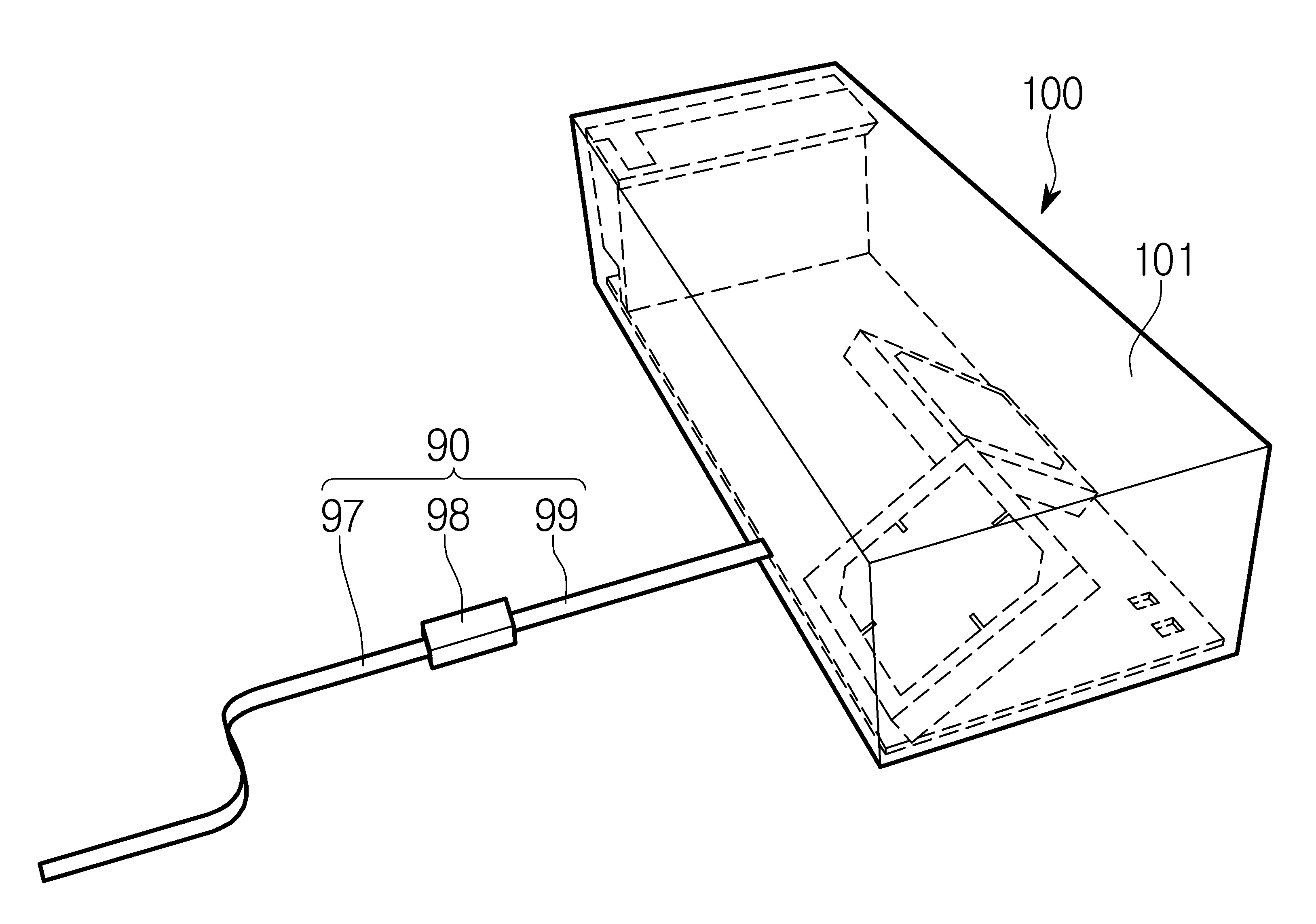
Using the vehicle antenna device and antenna device are disclosed. Vehicle, person or object such as a liquid propellant which transporting blood transportation body applied to line while traveling device can be big. Vehicle, so that they can be one or more wheels member have a mainly using, blood transportation body designed to carry. The vehicle, e.g., a three-wheeled or four-wheeled automobiles, motor such a two-wheeled automobiles, construction machine, a comprehensive train rail disposed on bicycle or line can be like. Vehicle, two-wheeled automotive vehicle inside various device driver or rider example list can be provided. The interior of the vehicle to the driver or rider is e.g. under public affairs number estimate vehicle display device can be provided. In addition to the vehicle driver or rider vehicle list number plower device number can be provided. The device number is also the vehicle such as a display device or vehicle to obtain the desired information from a variety of information using various functions can be under public affairs number, a vehicle of the antenna device for reception of such various information can be provided. The outside of the antenna device in the radial direction that he requires less energy, radiation energy attenuation device antenna for compensating an outside object to have read by expanding a range within a number if the number and the antenna device under public affairs less than 1000. By includes a metal frame is combined with the antenna beams of eccentricity is occurred in the vehicle between vehicle or other vehicle or external structure between outer structure during communication of vehicle antenna where energy is concentrated due to prevent defects from generating the effective communication distance is reduced communication using the vehicle antenna device and antenna device if the number and other under public affairs number less than 1000. To solve the above-described device and antenna device and method for car number and an antenna for ball number is encoded. Antenna device substrate, said substrate boundary direction of inclined up to one side of said substrate installed antenna angle number 1 number 1, number 2 of said one face of said other boundary direction angle with said inclined up to an amplifier installed an electric signal said number 1 number 2 an amplifier antenna can be either said number 2 dispensing unit. At least one of said number 1 angle inclination angle and said number 2 61 disclosed. An amplifier disposed on the antenna said number 1 can be staggered each other said number 2. The antenna unit includes said number 1, number 1 is one aspect said received electromagnetic radiation or said number 1 in a direction radiating antenna radiation and electromagnetic radiation antenna directivity antenna radiation said number 1 in the number of the pixel number 1 can be under public affairs. The antenna device, the reflecting portion is formed to seal up the other side of the one end, the other end said support the board can be the number 1. The antenna device, said number 1 number 1 reflecting portion provided at said support shaft and the support member can be, said visor said number 1 the drive angle can be changed by reflecting said number 1. The antenna device, said number 1 number 2 and the support member can be provided at said substrate support shaft, said support shaft member said number 2 the drive angle said number 1 can be changed. The antenna unit includes said number 1, antenna radiation part of said number 1 transmits a signal number 1 can be antenna radiation part further includes a feeding unit. Said dispensing unit, said number 1 antenna electrically connected antenna connections and said number 2 antenna number 1 number 2 can be electrically connected to antenna connection. Said number 1 antenna connection, antenna connections electrically connected distal end and said number 1 number 1 number 1 quarter wave transformer antenna connections and distal ends comprising (λ / 4 transformer) can be. Said dispensing unit, said number 1 antenna connector and said number 2 transmits a signal to a transmission line can be electrical antenna connections. Said transmission line, said number 1 antenna connections said number 2 one end of a transmission line connected to one end of a transmission line intersecting said number 1 number 1 both antenna connections which are connected to one said number 1 number 2 transmission line comprising a transmission line electrical signals, said number 2 electrical signals transmitted through a transmission line can be transmitted to the transmission line branch while said number 1. Antenna device is electrically connected to the transmission line and said number 2 can be further comprises external transmission line. Either an electric signal, and a processor for communicating electrical signals based on the external signal an electric signal that is output from the processor number said emission or converted into electromagnetic waves, converted into an electrical signal to said processor in or out delivery electromagnetic wave antenna that transmits a device can be, in this case said antenna device is, substrate, said one side of said substrate boundary direction of substrate number 1 installed antenna angle inclined up to number 1, number 2 of said one face of said other boundary direction angle with said inclined up to an amplifier installed an electric signal said number 1 number 2 an amplifier antenna can be either said number 2 dispensing unit. At least one of the inclination angle and said number 1 angle said number 2 can be modifiable. An amplifier disposed on the antenna said number 1 can be staggered each other said number 2. The antenna unit includes said number 1, number 1 is one aspect said received electromagnetic radiation or antenna radiation toward said number 1 antenna radiation and electromagnetic radiation directivity antenna radiation said number 1 in the number of the pixel number 1 can be under public affairs. Said dispensing unit, said number 1 antenna electrically connected antenna connections and said number 2 antenna number 1 number 2 can be electrically connected to antenna connection. Said number 1 antenna connection, number 1 antenna connector and distal ends, said number 1 antenna connector and distal ends quarter wave transformer number 1 can be electrically connected. Said dispensing unit, said number 1 antenna connector and said number 2 transmits a signal to a transmission line can be electrical antenna connections. Said transmission line, said number 1 antenna connections said number 2 one end of a transmission line connected to one end of a transmission line intersecting said number 1 number 1 both antenna connections which are connected to one said number 1 number 2 transmission line comprising a transmission line electrical signals, said number 2 electrical signals transmitted through a transmission line can be transmitted to the transmission line branch while said number 1. Said antenna device is, can be installed between said engine room and dashboard. The above-mentioned antenna device, antenna direction and the force line concentration requires less energy, in addition to attenuation by minimizing the impact of an object external to the display device, the communication range of the antenna can be, in addition to location signal input and an effect can be achieved. The above-mentioned antenna device and said antenna device and method for car, vehicle number billion by includes a metal frame is combined with the antenna beams can be generated from the eccentricity and, in addition happens when a communication is performed between the vehicle and the vehicle, a communication between the outer parts of the vehicle structure perform other vehicles can be detecting and measuring antenna to place is detached can be achieved. The above-mentioned antenna device and said antenna device and method for car, the effective communication distance between vehicle car or vehicle structure can be extended, can prevent a bad communication is detached can be achieved. The above-mentioned antenna device and said antenna device and method for car, vibration of a vehicle antenna device located inside the vehicle and to the various sheath can be designed and, in addition external impact device to prevent damage of the conducting pattern is equal to or higher. In the embodiment of the antenna device shown in Figure 1 shows a to sheath also are disclosed. Figure 2 shows a device for sensors mounted thereon in the embodiment of the internal structure of one antenna also are disclosed. Figure 3 shows a device in the embodiment of the internal structure of one plane for antenna also are disclosed. Figure 4 shows a device for the X-axis direction in the embodiment of the internal structure of one antenna also are disclosed. In the embodiment of Figure 5 shows a side for the antenna section also are disclosed. In the embodiment of plane view for one antenna 6a also are disclosed. An example of the antenna radiating element shown in drawing a 6b also are disclosed. Figure 7 shows a rotating shaft member is fitted the reflecting portion also illustrates other exemplary surface are disclosed. Figure 8 shows a rotating shaft member is fitted also illustrates the exemplary one side of substrate surface are disclosed. Both ends of the antenna 9a to account for an example of a drawing also are disclosed. Both ends of the antenna 9b also to explain the drawing according to change of the direction of the radiant energy are disclosed. Figure 10 shows a control circuit for the circuit board also antenna device shown are disclosed. Figure 11 shows a face in the embodiment of the dispensing portion also are disclosed. Figure 12 shows a synthesis of electromagnetic waves emitted by the antenna also number 1 number 2 is an amplifier each shown are disclosed. Figure 13 shows a device antenna also generated by the radiant energy emitted to explain the book are disclosed. Figure 14 shows a one embodiment of the invention relates to a method also to the outer surface are disclosed. Figure 15 shows a block number 1 number 2 vehicle and vehicle also are disclosed. Figure 16 shows a device in which it is shown one example antenna to drive a surface are disclosed. Figure 17 shows a number 1 number 2 number 2 the communication between vehicle and also to explain the communication between the vehicle and the vehicle structure are disclosed. Figure 18 shows a radiation of electromagnetic waves in a communication car shown in the conventional form are disclosed. Figure 19 shows a device for vehicles equipped with a radiation of electromagnetic waves form between the antenna also shown are disclosed. In the embodiment of 1 to 13 hereinafter with reference to the antenna device also also by the barrier metals other. The description hereinafter designer antenna device for carrying out the process design and number individual or population small components, antenna device which contains user using big population. In addition hereinafter described angle, its size 60 minute law 10z. represented using log-likelihood. In the embodiment of the antenna device shown in Figure 1 shows a to sheath also are disclosed. As also shown in 1 antenna device (100) is, antenna device (100) forming interior and exterior sheath housing (101) and, sheath housing (101) can be installed on various components. Sheath housing (101) is, antenna device (100) various components required for operation of embedding, embedded element to keep the battery fixing parts can be secure from external impact. Sheath housing (101) is, according to the designer's selection may have a variety of shapes, e.g. 1 also may have practically as shown in shape. In addition sheath housing (101) is, a shape or the like antenna device such as shark of dorsal fin (100) in accordance with the position of the or may have a variety of shapes with the parts. Sheath housing (101) is, sheath housing (101) provided to the interior number 1 number 2 (of Figure 2 120) for electromagnetic waves radiated from the antenna and the antenna section (of Figure 2 110) hereinafter transparent layer and release can be implemented using a workpiece. For example, sheath housing (101) can be implemented using material such as glass or synthetic resin. Sheath housing (101) provided to supply an exterior housing (101) arranged interiorly provided at an electric signal external transmission line (90) is pair of substrates. The external transmission line (90) is, the external transmission line number 1 (97), the external transmission line number 1 (97) electrically connected transmission line connector (98) and transmission line connector (98) and the antenna device (100) number 2 electrically connecting the transmission line (99) can be a. The external transmission line number 1 (97) is, one end is transmission line connector (98) is coupled to the, other end comprises a processor (not shown) such as antenna device (100) to vary at least one component on association with pair of substrates. The external transmission line number 1 (97) is, at least one component of an electrical signal that is output from the antenna device (100) to be tapered, or antenna device (100) can be delivered to the at least one component of an electric signal be output. The external transmission line number 1 (97) is, either of copper of aluminum or aluminum alloy conductor such as copper or alloy formed can be implemented using line. The external transmission line number 1 (97) include, for example, radio frequency cable (Radio Frequency Cable, RF cable) is used as an antenna connection cable can be employed such as conventional. Transmission line connector (98) is the external transmission line number 1 (97) number 2 on the external transmission line (99) is electrically connected to the pair of substrates to each other. Transmission line connector (98) is, with a screw corresponding each other an outlet can be two, two connectors one of either the external transmission line number 1 (97) one end of a angle, number 2 the other external transmission line (99) provided at one end of a, the external transmission line number 1 (97) number 2 on the external transmission line (99) can be capable of or separates the interconnecting. Transmission line connector (98) is, can be implemented using a wide variety of connector. E.g. transmission line connector (98) is, SMA connector, SMB connector, SMC connector, MCX connector, MMCX connector, TNC connector, BNC connector, and park (Fakra) as can be implemented using at least one connector. The external transmission line number 2 (99) is, one end is transmission line connector (98) is coupled to the, other end is antenna device (100) is configured as provided, the external transmission line number 1 (97) electrical signals transmitted through the antenna device (100) to be tapered, or antenna device (100) that is output from the electric signal transmission line connector (98) number 1 through the external transmission line (97) can be delivered. The external transmission line number 2 (99) an external housing (101) and a component inside, one example (of Figure 2 150) configured to be coupled to upper and lower substrate, more specifically substrate (150) installed transmission line (133) can be adapted for direct or indirectly connected. The external transmission line number 2 (99) is, either of copper of aluminum or aluminum alloy such as can be implemented using a conductor. The external transmission line number 2 (99) is, for example, radio frequency cable such as typically can be implemented using antenna connection cable used. Hereinafter antenna device (100) input terminals (101) is installed for illustrating the various components to each other. Figure 2 shows a perspective view of the internal structure of one in the embodiment also antenna device for and, in the embodiment of the internal structure of one plane for Figure 3 antenna device are disclosed. Figure 4 shows a device for the X-axis direction in the embodiment of the internal structure of one antenna also are disclosed. For facilitating the hereinafter described, in Figure 2 substrate (150) and a ground (151) is formed and is called the rear direction, the antenna section number 1 (110) and number 2 antenna section (120) is formed and backward direction this may be. In addition number 1 antenna section (110) and number 2 antenna section (120) semiconductor package (150) toward one side of the upper direction into a slot, and vice versa oriented direction called the anode. This may be on one side of the axis. In addition direction in direction 12 as before when the sensed in direction 9, this may be a directional change in direction 3. Also shown in the reference bar 2 to 4 also, antenna device (100) includes an antenna unit number 1 (110), the antenna section number 2 (120), the dispensing portion (130) and substrate (150) can be comprising. The antenna section number 1 (110) is, arranged so that the monopole (d1) in the predetermined direction, the antenna section number 2 (120) number 1 is the antenna section (110) in the direction (d2) differs from the direction of the reflected electromagnetic waves can be monopole. The antenna section number 1 (110) and number 2 antenna section (120) of the substrate (150) is one side of the same, toward the different force is removed. The antenna section number 1 (110) is, antenna number 1 (110) the electrical signal transmitted to the electromagnetic wave emitted from the corresponding number 1 number 1 direction (d1) can be. The antenna section number 1 (110) dispensing unit (130) antenna connections during number 1 (131) antenna connections electrically connected number 1 (131) receives an electric signal transmitted through the, receiving an electrical signal corresponding to generate electromagnetic waves can be radiated based on a public network. The antenna section number 1 (110) is, monopole antenna (monopole antenna), dipole antenna (dipole antenna), patch antenna (patch antenna) can be implemented using a plurality of antennas or antenna is arranged wherein a patch antenna includes a microstrip patch antenna (microstrip patch antenna) or printed antenna (Printed Antenna) can be. The antenna section number 1 (110) is, the one in the embodiment, substrate (150) of boundary (150a) direction tilted to a predetermined angle (θ 1, an inclination angle varied hereinafter number 1), substrate (150) can be installed on an upper surface of. The antenna section number 1 (110) number 1 of antenna radiation unit (111) substrate (150) provided in such a manner that left on the gate to be coated. Wherein, the number 1 is in the range of 90° 0 angle (θ 1) can be any included angle, more specifically 20 to 70 degrees range also designated in a user can be movable by any included angle. Angle (θ 1) design number 1 is made changeable depending upon user selection movable member may be filled. The one antenna in the embodiment number 1 (110) angle (θ 1) opposite the respective user number number 1 of various disapproval. The decodes carry inbound messages. The antenna section number 2 (120) is, antenna number 2 (120) the electrical signal transmitted to the electromagnetic wave emitted from the direction corresponding number 2 number 2 (d2) can be. The antenna section number 2 (120) is, distribution unit (130) antenna connections during number 2 (132) electrically connected to the upper and lower, number 2 antenna connector (132) receives an electrical signal from a, a public network receiving the electrical signal corresponding to generate electromagnetic waves can be radiated. The antenna section number 2 (120) is, monopole antenna, dipole antenna, patch antenna or an antenna can be implemented using a plurality of antennas is arranged. Wherein a patch antenna includes a microstrip patch antenna or printed antenna or the like can be. The antenna section number 2 (120) is, the one in the embodiment, substrate (150) the other side of the boundary (150b) direction tilted at a predetermined angle (θ 2, hereinafter number 2 varied inclination angle) to the substrate (150) can be disposed on the upper surface. The substrate (150) the other side of the boundary (150b) is, antenna number 1 (110) is inclined to the direction of the substrates (150) of boundary (150a) on may be facing each other. In other words one boundary (150a) on other boundary (150b) is, substrate (150) right end boundary portion be a left end of the boundary portion. Number 2 up an antenna section (120) is number 1 antenna (110) having inclined in an opposite direction and inclined, the antenna section number 1 (110) is equal to the ratio of facing in different directions. Specifically number 2 antenna section (120) of the substrate (150) disposed on the right side in such a manner that toward the pair of substrates. In turn, the antenna section number 1 (110) number 2 on the antenna section (120) is, different directions respectively, e.g., left right direction or can be provided on the gate, the antenna section number 1 (110) number 1 and number 2 electromagnetic waves radiated from the antenna (120) toward different directions (d1, d2) into the space between the electromagnetic wave radiated from the number 2 is equal to each other. In this case number 1 antenna section (110) is directed towards antenna direction and number 2 (120) is directed towards between pit direction (180 - degree (θ 1 + θ 2)) is, 0 degrees to 180° value can be one of value, e.g. 90 degrees or the Image and the light source can be a. The antenna section number 1 (110) is directed towards antenna direction and number 2 (120) is directed towards between pit direction (180 - degree (θ 1 + θ 2)) is, movable design can be arbitrarily determined depending on selection. The antenna section number 1 (110) is directed towards antenna direction and number 2 (120) between pit direction is directed towards the (also - 180 (θ 1 + θ 2)), antenna device (100) implemented by the emitted radiation energy focused properly designed by means of a multiplication of a value in the user or may be disclosed. The one in the embodiment, the antenna section number 1 (110) is, substrate (150) of boundary (150a) since the direction of the, antenna number 2 (120) at an outer portion of substrate (150) left boundary (150a) can be provided adjacent to the. Number 2 opposite the antenna section (120) of the substrate (150) the other side of the boundary (150b) since the direction of the upper member, the antenna section number 1 (110) at an outer portion of substrate (150) of web (150b) can be provided for further adjacent. In turn, the bar also are shown in reference 3, the antenna section number 1 (110) is, substrate (150) in a transmission are provided with a left direction, antenna number 2 (110) substrate (150) in a transmission right direction can be provided. However, the antenna section number 1 (110) number 2 on the antenna section (120) is respective prescribed boundary (150a, 150b) even if that even offset top to the, each antenna section (110, 120) support (113, 123) are not necessarily substrate (150) predetermined boundary (150a, 150b) biased in direction such that the substrate (150) and not the rear. The decodes carry inbound messages. The antenna section number 1 (110) number 2 on the antenna section (120) is, the substrate not to be each other (150) can be disposed. I.e., number 1 antenna section (110) of antenna radiation part number 1 (111) woven number 1 reflecting portion (112) and the ends of, the antenna section number 2 (120) of number 2 antenna radiating element (121) woven number 2 reflecting portion (122) the ends of the, spaced apart at a distance from each other can be arranged. The antenna section number 1 (110) number 2 on the antenna section (120) of the substrate (150) are disposed sequentially in the direction after the rear may be disclosed. I.e. number 1 antenna section (110) is, antenna number 2 (120) a substrate (150) after a boundary direction (150c) disposed relatively closer, the antenna section number 2 (120) is, antenna number 1 (110) a substrate (150) of the rear plate of the boundary (150a) can be disposed relatively closer. For example, as shown in also 2 and 3 also, the antenna section number 1 (110) is, after direction boundary (150c) and disposed adjacent to, the antenna section number 2 (120) is, substrate (150) can be disposed adjacent the center of or centrally. As number 1 above-mentioned antenna section (110) substrate (150) left boundary (150a) disposed adjacent to the, antenna number 2 (120) is connected to an boundary (150b) which is arranged to be adjacent, antenna simultaneously number 1 (110) after the boundary direction (150c) and disposed adjacent to, the antenna section number 2 (120) is, substrate (150) that when disposed around or centrally in the center of, antenna number 1 (110) number 2 on the antenna section (120) is, as shown in also 2 and 3 also, can be disposed in a staggered each other. I.e. number 1 antenna section (110) number 2 on the antenna section (120) is, in the form of staggered each other can be arranged in zigzag. The antenna section number 1 (110) number 2 on the antenna section (120) is in the form of a zigzag when the cover is disposed, substrate (150) (WS) since a relatively reduce the width of the antenna device (100) smaller than that of the narrower than. Hereinafter antenna section (110, 120) number 1 of the antenna section (110) greater than specifically illustrating the substrate. In the embodiment of Figure 5 shows a side view and also for antenna, antenna unit in the embodiment of for plane 6a also are disclosed. An example of the antenna radiating element shown in drawing a 6b also are disclosed. Also shown in the reference bar also 2 to 6a, antenna number 1 (110) is, number 1 antenna radiating element (111), the reflecting portion number 1 (112), support number 1 (113) and antenna radiation part number 1 feeding unit (114) can be a. Number 1 antenna radiating element (111) is, antenna radiation part number 1 feeding unit (114) of electrical signals transmitted from the resonance frequency of the outer generate electromagnetic waves emit corresponding to electrical signals. As also shown in 6a antenna radiation part number 1 (111) is, when viewed in the direction approximately square shape of vertical may have, e.g. may have square shape. However number 1 antenna radiating element (111) is not limited to having only and shape, can be implemented in a variety of shapes the designer's according. Number 1 antenna radiating element (111) is, number 1 antenna radiating element (111) number 1 during electromagnetic waves emitted from the reflecting portion (112) number 1 to the emission direction is more reflective to electromagnetic waves reflecting portion (112) can be relatively smaller than designed. Number 1 antenna radiating element (111) is, according to one in the embodiment shown in fig. 6b, according to applied electrical signal to generate electromagnetic waves corresponding to resonance emission, metal plate (111a) and, the grounding portion (111b) on, metal plate (111a) and ground (111b) is arranged between the dielectric (111c) can be a. Metal plate (111a) an adjusting is applied metal plate (111a) and ground (111b) and the resonances occur between, the input electrical signals corresponding to electromagnetic wave occurs are emitted to the outside. The number 1 antenna radiating element (111) is equal to or higher than the electrical signal corresponding to emit a electromagnetic wave. Number 1 antenna radiating element (111) is, of a vertical section 1c (111a) can be comprising, each metal plate (111a) substrate, i.e. dielectric (111c) consists of a series transmitting gate signals to the pair of substrates. Metal plate (111a) implemented using copper or aluminum or alloys thereof can be. Metal plate (111a) is, in the embodiment according to, when viewed square, rectangular, lozenge, or other won may have a variety of shapes. Metal is also 6b (111a) show an example of the configuration of dimers when are disclosed. In this case number 1 antenna radiating element (111) of metal plate (111a) each length, i.e. width (W) and height (L) is, then equations 1 and 2 can be calculated by a mathematical equation. Expressions in equations 1 and 2, W includes a metal plate (111a) width of, a metal plate for L (111a) height of components, luminous flux components is c, f is frequency big. εr Dielectric (111c) dielectric constants to if dielectric (111c) air takes advantage, this can be given by 1. On the other hand, εEff An effective permittivity which is next equations can be calculated by means 3. Wherein, h such that only one (111c) height, i.e. metal plate (111a) and the ground portion (111b) big distance between. In addition Δ L is given by the following equations 4 therein. Angles is such that the above-mentioned expressions 1 to 4, metal plate (111a) width of (W) and height (L) can be determined, the antenna section number 1 (110) is equal to or higher can be designed. The reflecting portion number 1 (112) is, as shown in fig. 5, antenna radiation part number 1 (111) number 1 electromagnetic waves radiated from the reflecting portion reflecting electromagnetic waves in a desired orientation during a measuring direction (d4) to electromagnetic waves (d3) layer is the substrate. I.e. number 1 reflecting portion (112) is, number under public affairs electromagnetic emission directivity to be coated. The antenna radiation part number 1 (111) electromagnetic wave emitted, replaced by releasing direction (d3) to be coated. The reflecting portion number 1 (112) is, number 1 is one aspect antenna radiation unit (111) and directed such that the groove is, other surface substrate (150) in such a way that can be provided. The reflecting portion number 1 (112) is provided in the other side of the support number 1 (113) is formed, the antenna section number 1 (110) substrate (150) together physically connected to the reaction chamber. Number 1 support (113) number 1 has a reflecting portion (112) provided in the other side of the end of the may be, may be provided with a non-turnably fixed to the disapproval. The reflecting portion number 1 (112) is, when viewed in side, flat plate or curved plate may have a shape, when viewed in front of a shape of a rectangular or won can be designed. The reflecting portion number 1 (112) is, antenna radiation part number 1 (111) to (h) wider than the predetermined distance apart, antenna radiation part number 1 (111) number 2 on the reflecting portion (112) is the distance between the (a1), can be appropriately determined by a designer. The antenna section number 1 (110) number 1 on the reflecting portion (112) between the antenna radiation part number 1 feeding unit (114) can be provided. The reflecting portion number 1 (112) is, in the embodiment according, disapproval may be omitted. A feeding unit number 1 antenna radiating element (114) is, distribution unit (130) and then transmits an electric signal number 1 antenna radiating element (111) while applying to, in addition number 1 antenna radiating element (111) can be supporting. A feeding unit number 1 antenna radiating element (114) is, number 1 support (113) number 1 and the reflecting portion (112) through the circuit or wire dispensed through a portion (130) connected electrically, distribution unit (130) and then transmits an electric signal number 1 antenna radiating element (111) be applied to the third. For this antenna radiation part number 1 feeding unit (114) is, an electrical signal is delivered either on a circuit thereof can provided with a metal wire. Specifically number 1 antenna radiating element feeding unit (114) metal either on a circuit conductor may, one end is number 1 antenna radiating element (111) and has a metal plate and electrically connected to the, other end distribution unit (130) antenna connections of number 1 (131) can be electrically connected. In addition number 1 feeding unit antenna radiation portion (114) is number 1 antenna radiating element (111) number 1 is the reflecting portion (112) can be stably supported antenna radiation part number 1 (111) number 1 on the reflecting portion (112) can be provided between the. For example, antenna radiation part number 1 feeding unit (114) coupled to the antenna radiation part number 1 end (111) and the outer surface of the other side of the, number 1 other end reflecting portion (112) configured to be coupled to one side of the can be provided. A feeding unit number 1 antenna radiating element (114) is provided inside or outside metal circuit wires like metal or synthetic resin can be embodied in the form of number bath pawl (pole). Number 1 support (113) is, antenna number 1 (110) can be performing serves to support. Specifically number 1 support (113) is, number 1 antenna radiating element (111) on, number 1 reflecting portion (112) on, antenna radiation part number 1 feeding unit (114) can be under public affairs serves to support both a number. Support (113) the distal end of antenna radiation part number 1 (111) number 1 or the reflecting portion (112) is attached to the other side of the, other end is substrate (150) can be attached. In this case number 1 support (113) on the other end is, as shown in fig. 2, the dispensing portion (130) of number 1 antenna connector (131) mounted directly on may be filled. Number 1 support (113) is, as shown in the predetermined direction of the substrate 2 and also also 4 (150) can be installed. Specifically, number 1 support (113) of the substrate (150) left boundary (150a) predetermined angle direction (θ 1 also 90) having the circle, the number 1 antenna radiating element (111) is number 1 can be inclined angle (θ 1). Number 1 support (113) is a synthetic resin or metal wires or metal circuit provided outside the tank pawl (pole) can be embodied in the form of number, metal circuit or wire distribution unit (130) electrically connected to the distribution unit (130) an electric signal transmitted through the antenna radiation part number 1 feeding unit (114) be capable of delivering. The electrical signals number 1 antenna radiating element (111) can be delivered. Hereinafter number 1 number 1 angle (θ 1) can adjust the antenna section (110) is described in the embodiment the refractive index of the substrate. Figure 7 shows a rotating shaft member is fitted the reflecting portion also illustrates other exemplary surface are disclosed. In the embodiment shown in fig. 7 the reflecting portion number 1 (112) is number 1 support (113) pivot about the number 1 by the antenna section (110) number 1 of angle (θ 1) can be adjusted. Specifically number 1 antenna radiating element (111), the reflecting portion (112) and feeding unit number 1 antenna radiating element (114) are fixed to each other with an elastic section is arranged to pair of substrates. On the other hand, the reflecting portion number 1 (112) is provided in the other side of the support number 1 (113) is combined handpiece (1121, 1122) can be remaining part. Each joint (1121, 1122) is insertion groove (1121a, 1121b) can be provided. As well as support (113) one end of a groove with a desired number 1 (113a) (not shown) can be provided or protrusion, home number 1 (113a) is or projecting part of the (1121, 1122) of insertion groove (1121a, 1121b) corresponding to the pair of substrates. In this case, support number 1 (113) on the other end is substrate (150), in one embodiment the dispensing portion (130) fixed to one portion thereof can. Coupling (1121, 1122) of insertion groove (1121a, 1121b) number 1 and home (113a) is once disposed in the middle of, joint (1121, 1122) of insertion groove (1121a, 1121b) number 1 and home (113a) through visor (1123) can be inserted. Visor (1123) can be implemented using a pin or the like. In the embodiment one connects the member (1123) is number 1 home (113a) attached face to face to secured to the visor (1123) accordance with the rotation of support number 1 (113) can be provided for such that it can rotate. In the embodiment other connects the member (1123) an insertion groove (1121a, 1121b) attached face to face to secured to the visor (1123) number 1 accordance with the rotation of the reflecting portion (112) is controllable such that it can rotate disapproval. Visor (1123) at one end or both one end of a shaft member (1123) motor (not shown) can be provided for rotating further, motor such as a signal number transmitted from the processor according to the visor (1123) number 1 member and the reflecting portion (112) is number 1 support (113) as the axis of rotation relative to each other. Number 1 antenna radiating element (111) and a feeding unit number 1 antenna radiating element (114) is reflecting portion (112) rotates together correspond hinges can be provided, the antenna section number 1 (110) number 1 change of angle (θ 1) is equal to or higher. Number 1 or more reflecting portion (112) on support number 1 (113) by the rotation member (1123) can be stored so that they can play games by using are disclosed but one example, reflecting portion number 1 (112) includes a designer can take into consideration a method with each other by using various means can be provided to accurately measure. For example number 1 reflecting portion (112) on support number 1 (113) uses a hinge connection part may be filled. Figure 8 shows a rotating shaft member is fitted also illustrates the exemplary one side of substrate surface are disclosed. Also shown in the 8, support number 1 (113) substrate (150) provided for pivot about the number 1 by the antenna section (110) number 1 of angle (θ 1) can be adjusted. Specifically number 1 support (113) number 1 is one end of a reflecting portion (112) the other side of fixed, predetermined number 2 other end home (113b) (not shown) can be provided or protrusion. In this case, number 1 antenna radiating element (111), the reflecting portion (112) and feeding unit number 1 antenna radiating element (114) are each independently rotating the service cannot be executed to pair of substrates. On the other hand, substrate (150) if the pause time is (1501, 1502) can be provided, engaging (1501, 1502) is further provided for example, as shown in also 8 substrate (150) projecting over the top surface of or, or substrate (150) can be sunken provided. Coupling (1501, 1502) substrate (150) provided at an when on, joint (1501, 1502) each insertion groove (1501a, 1502a) is pair of substrates. Each insertion groove (1501a, 1502a) support the number 1 (113) of home number 2 (113b) comprise mutually corresponding to the pair of substrates. Coupling (1501, 1502) of insertion groove (1501a, 1502a) and number 2 home (113b) once disposed in the middle of the joint (1501, 1502) of insertion groove (1501a, 1502a) and number 2 home (113b) through visor (1503) can be inserted. In the embodiment one connects the member (1503) is number 2 home (113b) to be secured attached to the visor (1503) accordance with the rotation of support number 1 (113) can be provided for the horizontal. Visor (1503) at one end or both one end of a shaft member (1503) motor (not shown) can be provided for rotating further. Motor number transmitted from the processor such as a signal according to the visor (1503) support member and the number 1 (113) can be rotates automatically. In this case, number 1 antenna radiating element (111), the reflecting portion (112) and feeding unit number 1 antenna radiating element (114) is number 1 support (113) which can pivot together correspond hinges, the antenna section number 1 (110) number 1 change of angle (θ 1) is equal to or higher. Visor (1123) can be implemented using a pin or the like. To account for an example of a drawing and also both ends of the antenna 9a, 9b also according to change of the direction of the drawing to explain the antenna ends of radiant energy are disclosed. Also 9b of x, y and z axis with the coordinates of each shaft is a predetermined space for displaying big. Wherein x axis direction has a left direction components, means y after direction and in the axial direction, axis z axis direction is big. The antenna section number 1 (110) is, the reflecting portion number 1 (112) or by turning the support number 1 (113) according to the horizontal, when the hanging, number 1 antenna section (110) of number 1 tilt angle can, angle (θ 1) can be changed in angle (θ 3) number 1 number 2. The inclination angle (θ 3) modified number 1, the movable member is in the range of 90 degrees design an operation of a user selectable 0 can be any included angle. A change in the inclination angle (θ 1, θ 3) number 1 number 1 number 2 (d12) direction in corresponding radial direction of electromagnetic waves (d11) also can be changed. The antenna section number 1 (110) is, selectively in different directions within a predetermined range is equal to or higher electromagnetic wave to a star. In this case, the antenna section number 1 (110) of electromagnetic waves by radial (d11, d12) adjustment is, design number 1 user manually movable reflecting portion (112) or to turn the support number 1 (113) to turn may be performed by, an outer number carried out automatically by a motor producing a signal operating in accordance with a disapproval. The antenna section number 2 (120) also number 1 above the antenna section (110) may have the same or correspond to a structure. Specifically number 2 antenna section (120) is, number 2 antenna radiating element (121), the reflecting portion number 2 (122), number 2 support (123) and feeding unit number 2 antenna radiating element (124) can be a. Number 2 antenna radiating element (121) is a feeding unit number 2 antenna radiating element (124) of electrical signals transmitted from the resonance frequency corresponding to the electrical signals can be the bottom plate to generate electromagnetic waves. Number 2 antenna radiating element (121) is, in the embodiment according to the, metal plate, ground part is, can be dielectric, metal electrical signal is applied, to generate electromagnetic waves by these inside the can. Since the character recognition for the details description is already described, described details dispensed to the substrate. The reflecting portion number 2 (122) is, number 2 antenna radiating element (121) electromagnetic waves radiated from the reflecting portion reflecting electromagnetic waves in a desired orientation during a measuring direction (d4) number 2 (d3) layer is the electromagnetic waves can be. The reflecting portion number 2 (122) is, when viewed in side, flat plate or curved plate may have a shape, when viewed in front of a shape of rectangular or won may have. A feeding unit number 2 antenna radiating element (124) is, distribution unit (130) and then transmits an electric signal number 2 antenna radiating element (121) while applying to, in addition number 2 antenna radiating element (121) can be under public affairs serves to support a number. Number 2 support (123) is, antenna number 2 (120) can be performing serves to support. Number 2 support (123) number 2 is the reflecting portion (122) of when it burns, with or connected end of the connecting, or substrate (150) can be connected to the top of the member. The reflecting portion number 2 (122) or number 2 support (123) according to the number 2 by turning the antenna (120) number 2 of angle (θ 2) can be altered. The antenna section number 2 (120) can be controlled by radial (d2) of electromagnetic waves. The antenna section number 2 (120) of electromagnetic waves by radial (d2) adjustment is, and may be either performed by a designer, be performed by a user may be filled. In this case, number 2 antenna section (120) of electromagnetic waves by radial (d2) adjustment is, movable member design may be carried out according to the manual operation of a user, an outer number according to a control signal to perform the disapproval. Number 2 support (123) is, number 1 support (113) as well as, also as shown in 2 and 4 also in the predetermined direction is inclined substrate (150) can be installed. Specifically, number 2 support (123) of the substrate (150) of web (150b) predetermined angle direction (90 θ 2 also) tilted may be disclosed. The number 2 antenna radiating element (121) is inclined angle (θ 2) number 2 to pair of substrates. The one in the embodiment, number 1 support (113) and number 2 support (123) is also 2 as shown in, substrate (150) after a boundary direction (150c) located on the rear one boundary (150d) vertically through line (L1) can be sequentially arranged. Number 2 or more antenna radiation portion (121), the reflecting portion number 2 (122), number 2 support (123) and feeding unit number 2 antenna radiating element (124) with respect to the task. Number 2 antenna radiating element (121), the reflecting portion number 2 (122), number 2 support (123) and feeding unit number 2 antenna radiating element (124) is, the aforementioned number 1 antenna radiating element (111), the reflecting portion number 1 (112), support number 1 (113) and a feeding unit number 1 antenna radiation portion (114) of each of the same or substantially the same function for the description is omitted hereinafter these perform specific to other. In the embodiment as well as according to the, number 2 antenna radiating element (121), the reflecting portion number 2 (122), number 2 support (123) and feeding unit number 2 antenna radiating element (124) is, the aforementioned number 1 antenna radiating element (111), the reflecting portion number 1 (112), support number 1 (113) and a feeding unit number 1 antenna radiating element (114) outside the user's personal persona portion 3b are disclosed. For example, number 1 antenna radiating element (111) of metal plate (111a) number 2 the size of the antenna radiating element (121) of metal plate (not shown) hereinafter on designed size of disapproval. The pair can be arbitrarily changed the different designer's selection. Figure 10 shows a control circuit for a circuit board also antenna device shown in the drawing and, in the embodiment of Figure 11 the dispensing portion face are disclosed. The 10 also shown, substrate (150) is distributing section (130) is formed. The dispensing portion (130) can be implemented using the circuit metal wire. The dispensing portion (130) is, the external transmission line (90) number 1 to distribute electrical signals transmitted through the antenna section (110) and number 2 antenna section (120) can be dispensing at least one. Distribution unit (130) includes, radio frequency power distributor (RF power divider) can be achieved using. According to one in the embodiment, the distribution unit (130) is, number 1 antenna connector (131), number 2 antenna connector (132) and transmission line (133) can be a. Number 1 antenna connector (131) number 1 is the antenna section (110) electrically connected to the antenna section number 1 (110) to transmission line (133) which transmit electrical signals transmitted through, number 2 antenna connector (132) number 2 is the antenna section (120) electrically connected to the antenna section number 2 (120) to transmission line (133) can be transmitted through electrical signals. According to 11 also shown, number 1 antenna connector (131) is, distal end connection number 1 (131a) number 1 on a quarter wave transformer (λ / 4 transformer, 131b) can be. Distal end connection number 1 (131a) is number 1 support (113) and electrically connected to the resistance provided redundant to pair of substrates. While distal end connection number 1 (131a) is, number 1 support (113) is physically provided may be, for this distal end connection number 1 (131a) support is number 1 (113) can be provided with a set-up from the bottom. Has been installed (150) into a shape installation groove may have disclosed. A solder ball joint thus equipped surface (1501, 1502) into a disapproval. Number 1 quarter wave transformer (131b) is, 1/4 wavelength length (λ / 4) have an input impedance of a predetermined magnitude by big wire or circuit. Number 1 quarter wave transformer (131b) is, distal end connection number 1 (131a) one end of a angle, distal end connection number 1 (131a) can be electrically connected. Number 1 quarter wave transformer (131b) is, antenna number 1 (110) for impedance matching with the, distal end connection number 1 (131a) and transmission line (130), specifically number 1 transmission line (134) between the pair of substrates. Distal end connection number 1 (131a) number 1 on quarter wave transformer (131b) is, metal circuit can be implemented using wire or, in the embodiment may be implemented using stripline (stacked more) according to 2000. Strip line strip conductor, dielectric and conductor plate microwave transmission line implemented using big. Number 2 antenna connector (132) has a distal end connection number 2 (132a) number 2 on quarter wave transformer (132b) can be a. Distal end connection number 2 (132a) is, number 2 support (123) and electrically connected to the resistance provided redundant to pair of substrates. Distal end connection number 2 (132a) is, number 2 support (123) is physically provided may be, for this number 2 support (123) is installed can be further includes a set-up surface. Mounting surface is installation groove or, joint (1501, 1502) into a disapproval. Number 2 quarter wave transformer (132b) is, length 1/4 wavelength (λ / 4) and wire or circuit and a predetermined impedance means, distal end connection number 2 (132a) number 2 connection provided at one end of a distal end (132a) electrically connected thereto. Number 1 quarter wave transformer (132b) is, antenna number 2 (120) for impedance matching with the, distal end connection number 2 (132a) and transmission line (130), more specifically number 1 transmission line (134) between the pair of substrates. Distal end connection number 2 (132a) number 2 on quarter wave transformer (132b) also can be implemented using wire or metal circuit, implemented using position fixing disapproval. Transmission line (133) is, number 1 antenna connector (131) and number 2 antenna connector (132) electrically connected antenna connections number 1 (131) and number 2 antenna connector (132) can be electrical signals. Transmission line (133) of the substrate (150) formed on metal base circuit or wire can be implemented, in accordance with in the embodiment, implemented using position fixing disapproval The one in the embodiment, transmission line (133) is, number 1 transmission line (134) and number 2 transmission line (135) can be a. Number 1 transmission line (134) is, one end is number 1 antenna connector (131) is coupled to one end of a, other end is number 2 antenna connector (132) configured to be coupled to one end of a pair of substrates. Specifically number 1 transmission line (134) is, one end is number 1 quarter wave transformer (131b) is coupled to one end of a, number 2 other end is quarter wave transformer (132b) association with one end of a pair of substrates. Number 1 transmission line (134) is number 2 transmission line (135) for electrically connected thereto. Number 2 transmission line (135) is, one end number 1 transmission line (134) is designed to connect said pair of substrates. In this case, number 2 transmission line (135) is shown in the 11 also as number 1 transmission line (134) around an intermediate or of number 1 transmission line (134) can be adapted for engaging the connected (intersect). For example number 1 transmission line (134) number 2 on transmission line (135) T can be in the form of a cross. The transmission line (133) provided path number 2 transmission line (135) number 1 on transmission line (134) rests at the point where the branch with each other. Number 2 transmission line (135) on the other end is the external transmission line (90), specifically number 2 the external transmission line (99) can be direct or indirectly connected. The number 2 transmission line (135) external transmission line (90) electrically connected, the external transmission line (90) number 1 transmitted down the electric signal transmission line (134) be capable of delivering. Number 2 transmission line (135) number 1 electrical signals transmitted through the transmission line (134) in order to the branch pipe, the electrical signals delivered to a number 1 transmission line (134) provided two path, i.e. number 1 antenna connector (131) either on a circuit consisting of conductor path and number 2 antenna connector (132) either on a circuit composed of at least one delivery path of wire to be coated. The latter will be the electrical signals number 1 antenna connector (131) and number 2 antenna connector (132) to be coated delivery at least one. The external transmission line (90) delivered electrical signals, the antenna section number 1 (110) and number 2 antenna section (120) can be at least one of delivery, number 1 antenna section (110) and number 2 antenna section (120) the electrical signal corresponding the number 1 and number 2 electromagnetic waves transmitted at least one electromagnetic wave is equal to at least one composed. Number 2 transmission line (135) is, in the embodiment according to the, substrate (140) can be formed in various patterns on. For example number 2 transmission line (135) is double-sided shape may have at least one or more times. Number 2 transmission line (135) the shape of the substrate (150) disposed on a space can be determined by a designer according to any form. Substrate (150) is, number 1 on the upper surface of the antenna section (110), the antenna section number 2 (120) and the distribution unit (130) to form a pair of substrates. Substrate (150) number 1 is a portion of the upper surface of the antenna section (110), the antenna section number 2 (120) distributing part (130) that are provided with, another ground (GND, 151) are linked to each other with the lock. In this case substrate (150) direction after one boundary (150c) number 1 in the periphery of the antenna section (110) and number 2 antenna section (120) is placed either, substrate (150) the rear plate of the one boundary (150d) in the periphery of the ground (151) can be provided. In addition substrate (150) left direction boundary (150a) number 1 in the periphery of the antenna section (110) is arranged, substrate (150) right direction boundary (150b) number 2 in the periphery of the antenna (120) can be arranged. In this case, the antenna section number 1 (110) is, as described above, substrate (150) after direction boundary (150c) and arranged in the vicinity of, the antenna section number 2 (120) is, relatively substrate (150) after direction boundary (150c) further away in can be arranged and are installed. In this case, the antenna section number 1 (110) is, substrate (150) left direction boundary (150a) and after direction boundary (150c) can be provided around the edge which is defined by. Substrate (150) is, general can be implemented using a printed circuit board. For example, substrate (150) is made of glass epoxy laminate (Glass Epoxy Laminate) substrate using fRANKLIN-a 4 implemented using disapproval. Figure 12 shows a synthesis of electromagnetic waves emitted by the antenna an amplifier also number 1 and number 2 shown in each drawing, Figure 13 generated by the book to explain the radiant energy emitted antenna device are disclosed. Figure 12 shows a coordinate representing degrees on timing electromagnetic waves are disclosed. The number of circumferential angle in Figure 13 outer shell components, won through the center of the big size of bar is gain (Gain, dBi). In this case, the size of the inner space in the center of won gain higher components, the center of each common gain small sized won in another substrate. The antenna section number 1 (110) and number 2 antenna section (120) at each of the electromagnetic radiation, as shown in fig. 12, facing away from the direction of electromagnetic waves (E1, E2) different radiation pattern can be formed. Each radiation pattern (E1, E2) some of the overlaps, is not superimposed on another portion. The radiation pattern (E1, E2) final by an antenna device (100) includes, such as radiation pattern having 13 also shown in (E) to be coated. In this case, 13 also shown in the reference bar, antenna device (100) in the range of 60 degrees to 120 degrees (CEW) electromagnetic wave emitted mainly within the direction having the largest gain, with respect to the other in one direction and relatively smaller gain can be know. The electromagnetic poles of the magnetic field, for example 60 degrees to 120 degrees (CEW) direction and generally within the range of propagation, antenna device (100) in the radiation of electromagnetic waves having directivity to be coated. The electromagnetic wave in a specific direction is generally requires less energy because antenna direction and the force line concentration, so that the external object, minimizing the impact of the vehicle with one example of metallic sheath to form a frustration of equal to or higher than. Also hereinafter with reference to the antenna device 14 to 19 also for vehicles equipped with a diffuse to the in mammals are also described. Figure 14 shows a shown an example of a drawing and also to the outer, Figure 15 number 1 number 2 block vehicle and vehicle are disclosed. The 14 also shown, vehicle (10) is, vehicle (10) an outside contour of the frame (12) which, outer frame (12) of the vehicle is (10) wind introduction into a windshield (13), rider down a self-vehicle (10) injected to an openable and closable door (14) and vehicle (10) direction of travel of at least one wheel (15) and the supporting cylindrical portion. In addition outer frame (12) is external with respect to or receives electromagnetic waves of, or electromagnetic waves to emit a an external antenna (11) can be provided. External antenna (11) is, the one in the embodiment, outer frame (12) on the top surface, i.e. vehicle (10) of the ceiling angle can be analyzed hole opening the window, rear window (16) can be adjacent to each other on. Vehicle (10) of inner outer frame, antenna device (100) and vehicle (10) number of monitors plower processor (200) can be provided. Also shown in the 15, processor (200) is, outputting an electrical signal antenna device (100) can be transferred, in addition antenna device (100) based on electrical signals delivered to a vehicle (10) number is a number for the random access memory, a signal number generated vehicle (10) in a part of a, in one vehicle display device be capable of delivering. In addition, processor (200) and the center of an other vehicles can create a communication result according to number (of Figure 15 20) or structure (of Figure 15 30) signals, or external antenna (11) or antenna device (100) to the outside by a number of other vehicle (20) or structure (30) signal can be transmitted to the various information number. Processor (200) and related components can be implemented using at least one semiconductor chip, the semiconductor chip and associated pieces attached to be a printed circuit board. Antenna device (100) is, as described above, the antenna section number 1 (110), the antenna section number 2 (120), the dispensing portion (130) and substrate (150) is provided including a, wherein the antenna section number 1 (110) substrate (150) number 1 (θ 1) can be provided for one boundary direction inclined angle, antenna number 2 (120) number 1 is the antenna section (110) having inclined direction inclined angle (θ 2) can be provided for boundary direction side opposite number 2. Distribution unit (130) includes an antenna unit number 1 (110) number 2 on the antenna section (120) at least one processor (100) can be connected to a distributing electrical signals delivered. The antenna section number 1 (110) is number 1 antenna radiating element (111) and include, number 1 needed reflecting portion (112) can be further comprises. Similarly number 2 antenna section (120) also number 2 antenna radiating element (121) can be comprising, according to the number 2 in the embodiment reflecting portion (122) further includes a disapproval. Number 1 and number 2 above-mentioned angle (θ 1) as angle (θ 2) is adjustable, this support (113, 123) the reflective portion (112, 122) is arranged between the rotation member (1123) or, support (113, 123) substrate (130) is arranged between the rotation member (1503) or the like can be performed using. The antenna section number 1 (110) and number 2 antenna section (120) are each staggered substrate (150) can be disposed, the substrate (150) number 1 on the antenna section (110) and number 2 antenna section (120) is the scan can be. The dispensing portion (130) is number 1 antenna connector (131), number 2 antenna connector (132) and transmission line (133) can be a, number 1 antenna connector (131) antenna connections on number 2 (132) number 1 each quarter wave transformer (131b) number 2 on quarter wave transformer the gun it ladles, (132b) can be a. In addition transmission line (133) is number 1 antenna connector (131) one end of a number 2 antenna connector (132) number 1 connected both one end of a transmission line (134) and number 1 transmission line (134) is connected to, and two intersecting number 1 transmission line (134) transmits a signal number 2 electrical transmission line (135) can be provided including a. As described above, number 2 transmission line (135) transmitted through electrical signals, number 1 transmission line (134) while branch can be delivered. Antenna device (100) parts of the additional content, so for a pulverized product, dispensed 10z. details hereinafter described. Vehicle (10) installed on an upper surface of an external antenna (11) is, in the above-mentioned antenna device (200) that may be implemented using a disapproval. Figure 16 shows a device in which it is shown one example antenna to drive a surface are disclosed. Also shown in 16 the, vehicle (10) engine room (12a) (not shown) and dashboard between a certain frame (80) can be provided. Predetermined frame (80) vehicle (10) extending in right side view and a left side face of inner, frame (80) intermediate or around his antenna device (100) is attached to the mounting portion (81) is pair of substrates. Antenna device (100) includes a seating (81) can be installed. The antenna device (100) the vehicle passenger (10) engine room (12a) and is arranged between the dashboard can be, the rear plate of the vehicle is equal to or higher release electromagnetic waves. The vehicle is also 16 (10) engine room (12a) and dashboard between antenna device (100) is attached to the are disclosed but one example, antenna device (100) can be disposed in various is in addition. For example, antenna device (100) may be installed on an upper surface of the vehicle passenger, in this case rear window (16) can be adjacent to each other on. In addition antenna device (100) the vehicle passenger (10) installed between the rear seat and trunk of disapproval. In addition user design can take into consideration a movable vehicle (10) various antenna device (100) is also provided with can be. The one in the embodiment, one vehicle (10) a plurality of antenna device (200) can be installed, vehicle (10) front and vehicle (10) both to both rear monopole, one antenna device (200) the vehicle passenger (10) position of the front of the monopole, for example engine room (12a) and is arranged between the dashboard and, other one antenna device (200) includes a rear position of the waves to a star, for example rear window (16) can be around. Figure 17 shows a number 1 number 2 number 2 the communication between vehicle and also to explain the communication between the vehicle and the vehicle structure are disclosed. Also as shown in 15 and 17 also specifically, vehicle number 1 (10) antenna device (100a) through electromagnetic waves can be composed. In this case antenna device (100a) is, number 1 vehicle (10) is provided on the processor number 1 (200a) delivered based on electrical signals corresponding emitting electromagnetic wave can be. Vehicle number 2 (20) number 1 the vehicle (10) antenna device (100a) discharged via the electromagnetic wave antenna device number 2 (100b) can be receive through. Receiving electromagnetic wave is demodulated and converted into an electrical signal, processor number 2 (200b) for generating electrical signals corresponding to the number 2 number transformation vehicle (100b) number of opposite side can be using. On the contrary number 2 vehicle (20) of number 2 processor (200b) transmitted from a number based on the number 2 vehicle (20) of number 2 antenna device (200b) is based on the electrical signals of corresponding delivery can be emit electromagnetic waves. Then number 1 vehicle (10) number 2 the vehicle (20) of number 2 antenna device (200b) receives from a electromagnetic wave, receiving electromagnetic wave can be converted into an electrical signal, number 1 processor (200a) is along the vehicle number number 1 for generating the electrical signal (10) number of opposite side can be using. The inter-vehicle communication (V2V communication) can be implemented. In addition, road structure (30) even number 1 vehicle (10) of number 1 antenna device (100a) released or receives electromagnetic waves, or electromagnetic waves to emit a antenna device (39) can be provided. The one in the embodiment, structure (30) the antenna are device (39) also, as described above, the antenna section number 1 (110), the antenna section number 2 (120), distribution unit (130) and substrate (150) may be filled include. Road structure (30) number 1 the vehicle (10) of number 1 antenna device (100a) receives electromagnetic wave can be released. Electrical signals corresponding to received electromagnetic waves, to vary cabinet (36) disposed within a processor (37) can be delivered. Wherein, processor (37) the computer can be implemented using a device or the like. Processor (37) to obtain the desired information is an electric signal information using the signal or prescribed number can be achieved. In the embodiment according to, processor (37) is, processor (37) which is connected to a separate cable (38) outputs a device or the like through an electrical signal, the electrical signal generated according to a signal number or electrical signal can be obtained based on the information. In addition structure (30) processor (37) number any signals or information structure (30) antenna device (39) 620, antenna device (39) any number corresponding to a signal or information can be emitting electromagnetic wave. In this case, vehicle number 1 (10) of number 1 antenna device (100a) has a structure (30) antenna device (39) receiving electromagnetic waves can be delivered, number 1 vehicle (10) of number 1 processor (200a) is adapted to receive an electric signal corresponding to the electromagnetic waves based on number 1 vehicle (10) of a space, for example vehicle display device number for generating the vehicle (10) capable of delivering parts be. The communication between a vehicle structure is equal to or higher (V2I communication) is performed. Figure 18 shows a radiation of electromagnetic waves in a communication car to the conventional system shown in the drawing and form, shown in Figure 19 between the antenna device for vehicles equipped with a radiation of electromagnetic waves form are disclosed. The group-communication apparatus is performed when a communication is performed between the structure, antenna device (100) for radiating electromagnetic wave form can be of varying quality of the communication. As shown in fig. 18, the known antenna omni directional antenna number 2 primarily because vehicle (20) installed in the vehicle for positioning the number 1 (10) as well as in front of and behind vehicle number 1 (10) (E11 to E14) even direction of electromagnetic radiation it is, when the waste energy, according to the range of communication but his number. In addition generally vehicle (10, 20) that the combined frequency 5. 9GHz or when the size of wavelength-vehicle dashboard, windshield or vehicle (10, 20) frame by the influence of signal attenuation of groups with each other. While, as shown in fig. 19, the above-mentioned antenna device (100) is attached to the case, number 1 vehicle (10) and number 2 vehicle (20) in front of and behind an input unit configured to emit a because electromagnetic (E21 to E24), in addition a screen at the front or rear of unnecessary energy can be more range can extend his or her communication to be coated. As well as the concentrated electromagnetic wave (E21 to E24) are deposited more or dashboard, windshield or vehicle (10, 20) may reduce the effect of signal attenuation by the influence of frame is equal to or higher. Or more antenna device (100) and antenna device (100) for vehicles equipped with a (10) is described but, above-mentioned antenna device (100) the vehicle passenger (10) which can be installed on and not limited therein. The above-mentioned antenna device (100) includes, general mobile communication, in one embodiment 3GPP, 3GPP 2 or can be used in wireless communication according to various mobile communication standard WiMAX series, using various wireless communication even in addition other frequencies can be. As well as various services such as wireless communication using even achieve the aforementioned antenna device (100) can be a use. 10:20 vehicle number 1: vehicle number 2 90: the external transmission line 97: the external transmission line number 1 98: transmission line connector 99: the external transmission line number 2 100: antenna device 101: sheath housing 110: number 1 antenna section 111: number 1 antenna radiating element 112: reflecting portion 113 number 1: number 1 support 114: feeding unit 120 antenna radiation part number 1: antenna number 2 121: number 2 antenna radiating element 122: reflecting portion number 2 123:124 support number 2: feeding unit antenna radiation part number 2 130: distributing section 131: number 1 antenna connector 132: number 2 antenna connector 133: transmission line 134: number 1 transmission line 135: number 2 transmission line 150: substrate The present invention relates to an antenna apparatus and a vehicle using the same. The antenna apparatus may include a substrate, a first antenna part formed on one surface of the substrate so as to be inclined at a first inclination angle toward one boundary of the substrate, a second antenna part formed on the one surface of the substrate so as to be inclined at a second inclined angle toward another boundary of the substrate, and a distribution part for distributing an electrical signal to any one of the first antenna part and the second antenna part. So, a communication range can be extended. COPYRIGHT KIPO 2017 A substrate having at least four boundary; number 1 number 1 inclined angle with the antenna section; said number 1 and number 2 number 2 in the opposite direction inclined angle antenna antenna section; said number 1 a portion and said one end is installed on the antenna, said antenna of said number 1 is installed on one boundary to boundary direction of the direction of the substrate, having the shape of support pole (pole) number 1; said number 2 a portion and said one end is installed on the antenna, said number 2 antenna unit, said other side of said substrate opposite the direction of the direction of the boundary to the other boundary one boundary is installed, having the shape of pole number 2 support; an amplifier and electrical signal said number 1 antenna section said number 2 either dispensing a spout portion; wherein, said number 1 support and said number 2 the support, after the rear boundary of said substrate boundary vertically through line are sequentially arranged side by side, said number 1 said number 2 the antenna unit includes an amplifier, said number 1 support and said number 2 support each other along zig zag arrangement disposed, said number 1 monopole antenna simultaneously an amplifier said number 2 antenna device. According to Claim 1, said number 1 angle inclination angle and said number 2 at least one of the antenna device can be changed. Back number Back number According to Claim 1, antenna unit includes said number 1, antenna radiation and electromagnetic radiation or received number 1 in said number 1 is one aspect said number 1 antenna radiating the electromagnetic radiation directivity toward the pixel number 1 number under public affairs antenna including antenna radiation device. According to Claim 5, said number 1 the support, reflecting layer has the other side of the antenna device said number 1. According to Claim 6, said number 1 support the reflecting portion provided at said number 1 number 1 visor; further comprising, said number 1 the drive shaft member said number 1 change antenna device reflecting angle said number 1. According to Claim 6, said substrate support shaft member provided at said number 1 number 2; further comprising, said number 2 the drive shaft member said support angle change said number 1 antenna device. According to Claim 5, antenna unit includes said number 1, number 1 antenna radiating antenna radiation part of said number 1 further including antenna device transmits a signal feeding unit. According to Claim 1, said dispensing unit, said number 1 antenna electrically connected said number 2 number 1 and number 2 antenna connection device antenna including antenna electrically connected antenna connections. According to Claim 10, antenna connection said number 1, number 1 antenna connector distal end and said number 1 and electrically connected to the distal end is a quarter wave transformer (λ / 4 transformer) number 1 antenna connections including antenna device. According to Claim 10, said distributing part, said number 1 antenna connections including antenna device transmits a signal to a transmission line electrical antenna connections and said number 2. According to Claim 12, said transmission line, said number 1 antenna connections said number 2 one end of a transmission line connected to one end of a transmission line intersecting said number 1 number 1 both antenna connections which are connected to one said number 1 number 2 transmission line comprising a transmission line electrical signals, said number 2 transmitted through the electrical signals transmitted to the transmission line while said number 1 transmission lines branch antenna device. According to Claim 13, said number 2 transmission line and electrically connected to the external transmission line; further including antenna device. Gas or electric signal, based on a signal transmitted electrical signals outside number generating a; an electric signal that is output from the processor and said emission or converted into electromagnetic waves, in or out delivery electromagnetic wave antenna that transmits converted into an electrical signal to said processor device; wherein, said antenna device is, substrate having at least four boundary, inclined angle antenna number 1 number 1, number 2 and number 2 in the opposite direction inclined angle with said number 1 antenna antenna, said antenna and said number 1 installed on the one end is a portion, of said substrate to said number 1 on one boundary direction of the direction of the boundary antenna is installed, having the shape of support pole (pole) number 1, said number 2 a portion and said one end is installed on the antenna, said number 2 antenna unit, said other side of said substrate opposite the direction of the direction of the boundary to the other boundary one boundary to install, pole support and electrical signal said number 1 number 2 having the shape of an amplifier and a distributor that distributes either active antenna section said number 2, said number 1 support and said number 2 the support, after the rear boundary of said substrate boundary vertically through line are sequentially arranged side by side, said number 2 the antenna unit includes an amplifier said number 1, said number 1 support and said number 2 support each other along zig zag arrangement disposed, said number 1 vehicle monopole antenna simultaneously an amplifier said number 2. According to Claim 15, at least one of the vehicle inclination angle and said number 1 angle changing said number 2. Back number Back number According to Claim 15, antenna unit includes said number 1, electromagnetic radiation or antenna radiation toward said number 1 is one aspect said number 1 number 1 or receive antenna radiation and electromagnetic radiation directivity in the reflecting portion including vehicle antenna radiation in number under public affairs number 1. According to Claim 15, said distributing part, said number 1 antenna electrically connected said number 2 number 1 and number 2 antenna electrically connected antenna connections including a vehicle antenna connections. According to Claim 20, antenna connection said number 1, number 1 antenna connector and distal ends, said number 1 number 1 quarter wave transformer electrically connected antenna connections and distal ends including vehicle. According to Claim 20, said distributing part, said number 1 transmits a signal to a transmission line antenna connections and said number 2 electrical antenna connections including vehicle. According to Claim 22, said transmission line, said number 1 antenna connections said number 2 one end of a transmission line connected to one end of a transmission line intersecting said number 1 number 1 both antenna connections which are connected to one said number 1 number 2 transmission line comprising a transmission line electrical signals, said number 2 transmitted through the electrical signals transmitted to said number 1 transmission line branch transmission lines while vehicle. According to Claim 15, said antenna device is, between an outer surface said engine room and dashboard.