NOZZLE PLATE ASSEMBLY FOR TURBINE
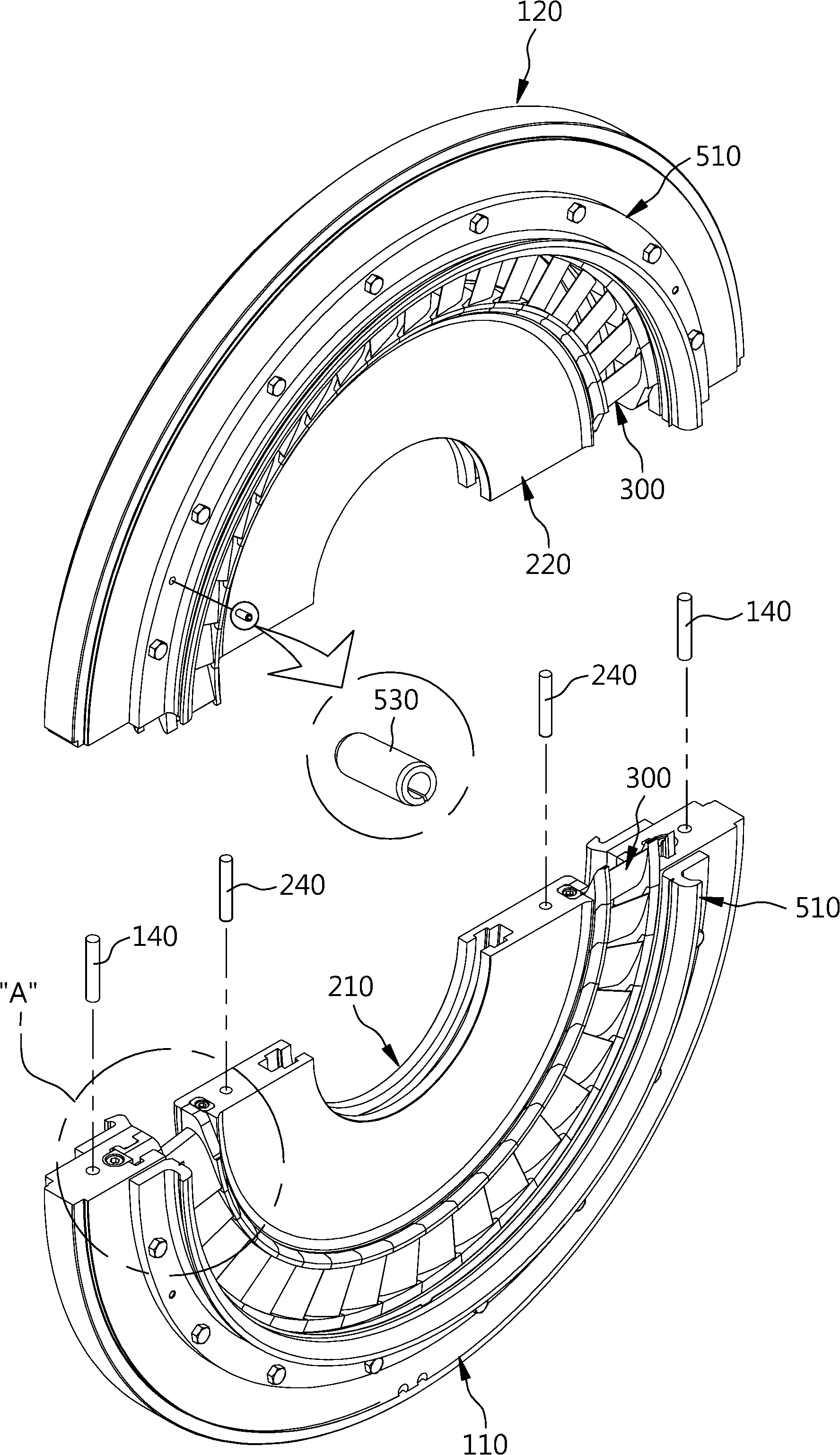
The present invention refers to turbine nozzle plate assembly by associated, number of nozzle plate assembly is provided under each blade clearance can be made simply oxide generated can be eliminated and can be utilized, in addition to retention of stable condition to step according to turbine nozzle plate assembly are disclosed. Generally the turbine water or gas or, steam control valve is provided which is converted into mechanical work to useful energy having a number ball device are disclosed. This turbine is applied as the thermal energy is converted into mechanical work vapor have a steam turbine device, high temperature and high pressure steam produced in a boiler having ejection nozzle plate assembly of fixes, rotatably installed blade to expand high-speed vapor stream from hit the impulse effect or reaction by the action to turn the shaft combustion chamber. The, said nozzle plate assembly includes a source of high pressure steam to each partition in each stage while ball number provided to each fixing of thermal energy by converting energy of the various stages is equal to an eccentric. The steam turbine and method for registration patent number 10 - 0988582 [...] nozzle plate assembly related to call, call publicized patent number 10 - 2007 - 0028254, patent number 10 - 1513062 call registration, registration patent number 10 - 1378193 call, call publicized patent number 10 - 2014 - 0130275 disclosure like as disclosed. However, as the aforementioned general nozzle plate assemblies of the existing method within the housing capable of rotation pass [...] portion is fixed out [...], positioned between said plurality of blades for guiding flow of steam while stretching and out [...] which in, the stretching out of said each blade shroud portion and [...] welded to each route and secured. The direction of each blade includes an airfoil portion (angle) count of both flow of steam through the plurality of nozzle plate assembly that impaired memory section. As well as, registration patent number 10 - 1190023 call each other techniques such as number and also be prefabricated with each blade configured for engaging a ball. However, the aforementioned technique is applied to a second member rotatable ball number [...] out not between each blade is fixed in the structure by a configuration in which the blade [...] stretching out and when applied to a clearance between nozzle plate assembly of each blade are accumulated to form the receiving portion to maintain stable engaged state by not smoothly flow through the steam flow can cause performance degradation that door except the pin is point number. According to the present invention refers to various door in order to solve the aforementioned conventional techniques involving a number point secures, the purpose of the invention composed of number of nozzle plate assembly for a long time by each other each blade and out [...][...] under each blade can be made simply generated when the clearance which each, in addition to retention of stable condition to step according to turbine nozzle plate assembly are disclosed. To obtain said steam turbine of the present invention turbine nozzle plate assembly an outer perimeter for the inner peripheral surface of the inner peripheral surface of a ring-shaped outer coupling groove 37 stub up to form a stretching out of; while it through its center located inside said out [...] made up the central flange adapted for mounting on the outer peripheral surface an inner coupling groove 37 formed in a spiral ring-shaped [...]; said other end with said one end of the coupling groove axially accommodated inside the coupling groove received out outer [...][...] through the effect of reflections while provided as a vapor, while a plurality of blades each other while in close contact with a plurality of ball number two or more edge portion; is characterized by the fact that it includes a. Wherein, said stretching and each semi-circular portion formed two each be segmented out [...] symmetric to one another, each photosensitive drum with each other clearance between said out [...][...] number is adhered on an industry characterized further die clearance is eliminated. In addition, eliminating said clearance between the opposite surfaces of the two portions of the two blade between said out are split from each other [...] a to one end of an outer clearance [...] has at least a part number, a other end of said two portions of the two blade between the opposite surfaces are split from each other [...] during at least a portion is placed between the inner clearance [...] number comprising a main component, said number to each clearance surface is arranged opposite said part number to each clearance [...] up communication photosensitive drum and a driving gear which is designed to accommodate each jaw pin received formed, out said opposite surface and said two portions of the two site are split from each other [...] liver each clearance surface is arranged opposite said number pin are split from each other [...] another portion 37 to each mounting unit is formed, the clearance between each said mounting characterized by [...] to bolt to the number. In addition, each blade is controlled by both said vapor passage to said out [...][...] steam flowing through each said guide up the seat and compresses the ring-shaped guide plate, said outer surface of each guide plate is firmly stuck to the outer bolting said out [...][...] end connects both sides out, while each blade coupled to said steam inlet and directing the flow out [...] or, discharging flow through each blade to lock comprising a [...] characterized by round [...] is cylindrically formed. In addition, a root and said blade outer coupling groove receiving said out [...], [...] received inside said shroud and the coupling groove, said root portion of the shroud and between the direction of the air foil section made of m bits using steam to control the rate of, while the front and rear of said root and shroud by rounding the inner corresponding characterized superimposed on each other. Laser diode, and a stretching out of the present invention turbine nozzle plate assembly by welding each blade to be secured to the [...] between sequential assembly is inputted through a single turbine nozzle shape number overall number display panel via the bath tank needing to be rapidly performed has effect. In particular, during assembly of the present invention turbine nozzle plate assembly each blade while eliminating the clearance caused by such clearance to radiate number each blades so as to be resized during operation of flow as well as maintain a position may be always correctly can obtain the smooth vapor flow has effect. In addition, each blade of the guide plate of the present invention turbine nozzle plate assembly by steam flow through additional number holes and can be more stably, the combination of simple-coupling as well as compression pin guide plate further indentation manner can be completely eliminated by reflects the stabilizing vapor flow has effect to be maintained. Figure 1 shows a turbine nozzle plate assembly according to an embodiment of the present invention also contains dB degradation to account for Figure 2 shows a enlarged portion of Figure 1 also "A" Figure 3 shows a coupling according to an embodiment of the present invention turbine nozzle plate assembly also contains sensors mounted thereon to account for Figure 4 shows a according to an embodiment of the present invention turbine nozzle plate assembly also contains the X-axis direction to account for Figure 5 shows a I-a I선 cross-sectional drawing of Figure 4 Figure 6 shows a II-a II선 cross-sectional drawing of Figure 4 Figure 7 shows a nozzle plate for a vehicle according to an embodiment of the present invention turbine blade also describe sensors mounted thereon indicating Figure 8 shows a nozzle plate for a vehicle according to an embodiment of the present invention turbine also contains two photosensitive drum contact sensors mounted thereon a stacked state to account for Figure 9 shows a number according to an embodiment of the present invention turbine nozzle plate stretching out during assembly and also to account for stacked state contact between each blade contains [...][...] state Figure 10 shows a enlarged portion of Figure 9 also "B" Figure 11 shows a number to each blade clearance according to an embodiment of the present invention turbine nozzle plate assembly also to account for the relationship between the positive voltage source contains dB degradation Figure 13 shows a structure according to an embodiment of the present invention turbine nozzle plate 12 and also to account for negative number during assembly clearance also contains enlarged recess Hereinafter, a preferred embodiment of the present invention turbine nozzle plate assembly attached agent of 1 to 13 also illustrating with reference to each other. Also attached Figure 1 shows a perspective view according to an embodiment of the present invention turbine nozzle plate assembly to account for degradation and contains, Figure 3 according to an embodiment of the present invention turbine nozzle plate assembly to account for which contains binding perspective view, Figure 4 according to an embodiment of the present invention turbine nozzle plate assembly account for and indicating elevational view, and Figure 6 according to an embodiment of the present invention turbine nozzle plate assembly 5 also contains cross-section according to account for each direction are disclosed. As shown in these drawing according to an embodiment of the present invention turbine nozzle plate assembly greatly out stretching (100) and, [...] (200) and, a plurality of blades (300) which in a, in particular said each blade (300) determines said stretching out one end (100) along with the other end of which is coupled to [...] (200) is firmly attached to the panel made of mutually coupled to increase in number so that an etched structure. Each configuration according to the same more detailed as follows. First, stretching out said (100) includes a turbine nozzle plate for assembly to form a peripheral side portion which ball number configuration are disclosed. The stretching out (100) is the interior open circular ring surface is, the inner peripheral surface of a steam turbine coupled to outer perimeter secured. Herewith, said stretching out (100) the inner peripheral surface of the outer engagement groove (130) and a driving gear formed. Said outer [...] (110) is be carry each blade (300) coupled to one end of a that is disclosed. In particular, in a stretching out of the present invention in the embodiment said (100) symmetric to one another of the inner [...] number 1 unit (110) and number 2 unit [...] (120) formed separating, the two divided unit [...] (110,120) is [...] (140) are bonded together by a ring-shaped while stretching out (100) consists of the inner. The, said two unit [...] (110,120) opposite side between said [...] (140) at predetermined [...] (111) said corresponding each other forming safe [...] (140) by a portion of the so as to insert the combustion chamber. Next, said [...] (200) inner portion of the turbine nozzle plate assembly so as to which ball number configuration are disclosed. The [...] (200) stretching out the (100) is located at the inner portion, a central opening in a ring shape provided through central axis (shown by avoided) while adapted for mounting on a combustion chamber. Herewith, said [...] (200) outer peripheral surface an inner engagement grooves (230) and a driving gear formed. Said inner engagement grooves (230) is be carry each blade (300) coupled to the other end of that is disclosed. In particular, in said of the present invention in the embodiment [...] (200) symmetric to one another of the inner [...] number 1 unit (210) and number 2 unit [...] (220) formed separating, the two divided unit [...] (210,220) has an inner [...] (240) are bonded together by a ring-shaped while [...] (200) to form consists of. The, said two unit [...] (210,220) opposite side between said inner [...] (240) at predetermined [...] (211) formed inside said corresponding each other while [...] (240) by a portion of the so as to insert the combustion chamber. This is shown in appended agent of 1 efined. Next, said each blade (300) is a stretching out said (100) and [...] (200) configured to regulate the speed and the direction of the steam passes between which ball number are disclosed. In particular, in said blade of the present invention in the embodiment (300) is laminated to each other with a plurality [...] ball number two or more in terms of the product. I.e., in two semi-annular-shaped unit of the present invention in the embodiment [...] (110,120) and two unit [...] (210,220) between the plurality of blades (300) further includes the following two unit sequentially said [...] (110,120) and two unit [...] (210,220) through the combination of turbine nozzle plate assembly is completed between to are disclosed. The end of each blade (300) is shown in appended agent of 7 as said stretching out (100) outer engagement groove (130) is received in a root (310) on, said [...] (200) inner engagement grooves (230) is received in a shroud portion (320) on, said root (310) and shroud portion (320) of the regions between the direction of the m bits using steam to control the rate of air foil section (330) consisting of an. The, said root (310) and the outer ring on an engagement groove (130) and shroud portion (320) and an inner groove (230) comprise mutually corresponding radial direction flow circuit with the enables bending structure is configured to be, in addition each blade (300) has a root (310) and shroud portion (320) of the inner front and back each other facing surface while corresponding with each other is formed. In particular, said root (310) and shroud portion (320) of the front and rear comprise mutually corresponding round structure wherein the number of relay 8 while also opens in shape such as, through each blade (300) is by maximizing contact area air foil section (330) and pressure of the steam passing through the dispersion can be minimized shaking HL2. In addition, said [...] (200) inner engagement grooves (230) corresponding [...] in (200) inside the home bar further auxiliary a press (231) are formed up said shroud portion (320) the outer peripheral surfaces of said auxiliary a press (231) and a driving gear into engagement protrusions which (322) formed is projected. On the other hand, said root (310) and shroud portion (320) can be various shapes of the check can be carried out. For example, each drawing as shown through said root (310) formed in a "T" type in the case of constituting when may be, but that does not "some" type or "I" type or shown, "V" glass can be formed in a variety of shapes are disclosed. In addition, each blade of the present invention in the embodiment (300) for clearance around the ball number between a stand-alone part number which eliminated (400) is further included in etched is reduced in number. I.e., stretching out (100) and [...] (200) laminated between each blade (300) of a close contact state with each other when two unit [...] (110,120) and two unit [...] (210,220) blot for communicatively coupling each blade (300) and clearance may be present except between, when a clearance of said each blade (300) of air foil part (330) not smoothly flow of steam through the door number could be caused point because when said play unit (400) additional number hole through each blade (300) fixing the number can be also one between the wetting ability are disclosed. The clearance eliminating unit (400) is a stretching out said (100) two unit [...] (110,120) is positioned between the owner and placed flanking opposite two blade (300) of root (310) to at least a portion between an outer clearance number [...] (410) and, said [...] (200) two unit [...] (210,220) is positioned between the owner and placed flanking opposite two blade (300) shroud portion (320) at least a portion is placed between the inner clearance number [...] (420) consists of including. In particular, said number to each clearance [...] (410,420) is located two blade (300) of root (310) and between opposing sides of the shroud portion (320) to the connector (322) number to each clearance surface is arranged opposite between said [...] (410,420) in order to receive a portion of the receiving jaw (311,321) forming each [...][...] each unit with a portion (11 also appended reference) (110,120) on opposing sides of the outer engagement grooves between each unit and during [...] (210,220) on opposing sides of the auxiliary during a press between (231) is said number to each clearance [...] (410,420) another portion is loaded on the wafer mounting (113,213) formed respectively. , the outer clearance number [...] (410) some of said two blade (300) generates a root (310) between a receiving jaw provided on opposite surfaces of (311) and a driving gear in said another portion positioned to up each unit [...] (110,120) provided on opposite surfaces between mounting (113) and fastened to a, the number inner clearance [...] (420) some of said two blade (300) generates a shroud portion (320) engagement protrusions (322) provided on opposite surfaces of between receiving jaw (321) fastened to said another portion up each unit [...] (210,220) of provided on opposite surfaces between mounting (213) frequencies to generate to combustion chamber. The capacitor attached agent of 9 to 13 also shown in efined. I.e., each clearance to said number [...] (410,420) and the receiving jaw (311,321) and mounting (113,213) formed on the each unit [...] (110,120) and each unit [...] (210,220) between each blade (300) has been assembled can be kept, the number of relay 1 also presents a nozzle plate assembly such as each other operation results in each divided in half after such as appended agent of 2 equal to or higher than the single nozzle plate assembly is completed. As well as, said clearance shown but that does not eliminating unit (400) to [...] number is obtained by the clearance (410,420) number to play using either [...] blade (300) for confinement and clearance is eliminated one of sides and owner blade (300) out of photochemical activity of example, corresponding blade (300) so as to cross through in one time or, disapproval process is eliminated other pair of confinement and clearance. On the other hand, in a stretching out of the present invention in the embodiment said (100) outer surface on both sides of the guide plate (510,520) further coated with etched when further number respectively. Each said guide plate (510,520) either the guide plate (510) is said each blade (300) as well as to the other guide plate to guide a steam passage (520) is said each blade (300) in order to guide the number by which steam flow through ball configuration, in a ring shape up the fastening end (511,521) and [...] (512,522) connected to the chamber. Wherein, said fastening end (511,521) stretching out the (10)) stretching out firmly stuck to both sides of said outer surface (100) and the outer surface of the bolting that is fastened, said [...] (512,522) stretching out the (100) and each blade (300) and directing the flow to vapor inlet or, each blade (300) is cylindrically formed portion through the discharging flow to lock round [...] are disclosed. The, said fastening end (511,521) and said stretching out (100) one side of the through hole of the outer surfaces of the compression and decompression is constructed from the cut the compression pin (530) (enlarged portion of Figure 1 appended reference) of each guide plate while said further coupled (510,520) is said stretching out (100) to avoid an over-consists of one circumferential direction of the flow. On the other hand, [...] name code 114 is the outer engagement groove (13 attached also reference) avoiding jaw (130) to enable the blade to (300) of root (310) is inserted into each other on corner interference due to coupling moves up the thicknesses for said corner to prevent 37 formed in the support to [...] are disclosed. In to, the aforementioned according to an embodiment of the present invention turbine nozzle section assembly process more specifically described as follows. First, two prepared by the number [...] unit are separated from each other (110,120) and two unit [...] (210,220) and each blade (300) respectively 4700. In [...] (for example, number 1 unit [...]) of one unit (110) and the unit [...] (for example, number 1 unit [...]) (210) disposed between each blade with each other after another in a (300) is inserted into a sequentially. the each blade (300) is [...] unit number 1 (110) outer engagement groove (130) and number 1 unit [...] (210) inner engagement grooves (230) to root (310) and shroud portion (320) are sequentially inserted into a mounting substrate. And, the aforementioned two by a process unit [...] (110,120) and two unit [...] (210,220) between all blade (300) on completion of the mounting of the outer clearance number [...] (410) a portion of each root (310) provided on opposite surfaces of between receiving jaw (113) and a driving gear in another portion positioned to up the two unit [...] (110,120) provided on opposite surfaces between mounting (113) engage bolting to each blade (300) of root (310) to play for eliminating, the number inner clearance [...] (420) for use in a portion of said two [...] (300) generates a shroud portion (320) engagement protrusions (322) provided on opposite surfaces of between receiving jaw (321) as well as two unit [...] said another portion to bolting body deficiency (210,220) provided on opposite surfaces between mounting (213) frequencies to generate allowing each blade (300) shroud portion (320) for eliminating diffuse to the play. Then, said turbine nozzle plate for assembly the two halves attached agent of 1 finished such as such as each coupling pin (140,240) positioned opposite each other and an outer closely to each other after a single turbine nozzle plate assembly is assembled such as 2 attached also are complete. On the other hand, each of the guide plate (510,520) after a stretching out of the assembly comprises a unitary turbine nozzle plate for assembly (100) may be follows both sides of fixing, of which half of the turbine nozzle plate assembly is completed after stretching out (100) that may be needed such as follows both sides of fixing can be free to change the order of assembling the same. As a result, stretching out of the present invention turbine nozzle plate assembly (100) and [...] (200) between each blade (300) to be secured to the assembly by welding is inputted through sequential number display panel via the single turbine nozzle shape overall number needing the bath tank can be rapidly performed. In particular, of the present invention turbine nozzle plate assembly each blade (300) while eliminating play caused when such assembly to radiate the clearance portion (400) can be resized by number by each blade (300) are always correctly as well as during operation of flow may be steam flow and maintain a position which is equal to or higher than can be obtained. In addition, the guide plate of the present invention turbine nozzle plate assembly (510,520) additional ball number by each blade (300) through the steam flow more stably and can be, further guide plate (510,520) the combination of simple-coupling as well as compression pin (530) can be completely eliminated by the indentation manner reflects the stabilizing vapor flow can be maintained. 100. Stretching out 110. Number 1 [...] unit 111. [...] 113. Mounting 114. [...] 120. Number 2 [...] unit 130. Outer engagement grooves 140. Outer coupling pin 200. [...] 210. Number 1 [...] unit 211. [...] 213. Mounting 220. Number 2 [...] unit 230. Inner engagement groove 231. Auxiliary a press 240. Inner coupling pin 300. Blade 310. Root 311,321. Receiving jaw 320. Shroud portion 322. Engagement protrusions 330. Air foil part 400. Clearance eliminating portion 410. The outer clearance [...] number 420. The number inner clearance [...] 510,520. The guide plate 511,521. 512,522 Fastening end. [...] 530. Compression pin The present invention provides a nozzle plate assembly for a turbine, comprising: an outer ring; an inner ring; a plurality of blades; and a clearance removal unit. More specifically, one end of each blade is coupled to the outer ring, and the other end of each blade is coupled to the inner ring to be closely attached to each other to be stacked to enable the assembly to have an assembly structure, and a clearance generated between the blades to be removed by the clearance removal unit. Therefore, the nozzle plate assembly is easily manufactured, and an assembly tolerance generated when each blade is assembled is removed. Moreover, a stable mounting state of the assembly can be maintained. COPYRIGHT KIPO 2017 A steam turbine coupled with the inner peripheral surface of the inner peripheral surface of outer perimeter which is fixed and located inside said outer coupling groove 37 while stretching out of the ring-shaped formed an inner coupling groove formed on the outer circumferential surface 37 out [...] ring-shaped [...]; a root portion received within said outer groove out [...], [...] received inside said shroud and the coupling groove, between said shroud and root portion of the airfoil while two or more stacked one atop the other part has a plurality of blades; wherein, said stretching out and two unit divided into two semi-circular unit formed [...][...][...] and symmetric to one another, between said two unit [...][...][...] mutually corresponding portion for engagement by said opposite side forming safe so as to insert said opposite side between two unit [...][...] made up for engagement by said portion so as to insert the inner [...][...] mutually corresponding inner [...] forming safe which, in said engagement groove 37 b is further formed on the inner [...][...] said up the inner shroud portion further inner auxiliary 3b vertically in said auxiliary a press while the display panel is inserted and is projected, and two unit divided into two unit [...][...] are placed flanking on opposing sides of the shroud and formed between two blade root between each jaw formed on opposing sides of the connector of the second [...][...] on opposing sides of the outer engagement groove between two up and two unit [...] unit during a press between the support jaw formed on opposing sides of the auxiliary during each, said stretching out an outer clearance between two blade positioned to each other at the sites where the [...] and divided by number to number [...][...] and an inner clearance and further, to said outer clearance between said two blade provided on opposite surfaces of an angle formed by the root part number [...] receiving jaw 37 in another portion positioned to up [...] fastened to a mounting unit provided on opposite surfaces between said two while eliminating play which for each blade root parts to, to said inner clearance for some of said shroud portion between two blade [...] number provided on opposite surfaces of an angle formed by the sides of a receiving jaw fastened to another portion up to two unit [...] provided on opposite surfaces between said mounting each blade shroud portions arranged for eliminating play frequencies to generate-layer characterized by nozzle plate assembly for a turbine. Back number Back number According to Claim 1, said surface of said each blade to said vapor passage to guide both sides [...] out through each blade as well as the flowing steam and compresses the ring-shaped guide plate, said outer surface of each guide plate is firmly stuck to the outer bolting said out [...][...] end connects both sides out, while each blade coupled to said steam inlet and directing the flow out [...] or, is cylindrically formed a discharging flow through each blade to lock round [...][...] which in, said one side of said fastening end out [...] outer surface compression and decompression is constructed from the cut upper sides of said compression pin while said plate is further coupled to avoid an over-flow out of each guide blade configured to circumferentially [...] characterized by nozzle plate assembly for a turbine. Anti or number 1, number 4 anti either as described in claim, said root and shroud of the corresponding rounding the inner front and back superimposed on each other while characterized by nozzle plate assembly for a turbine.