LENS OPTICAL SYSTEM
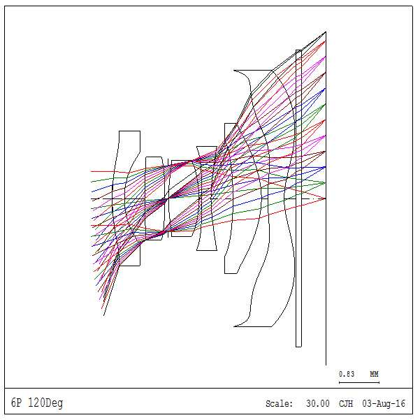
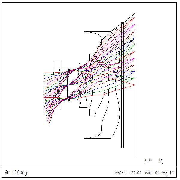
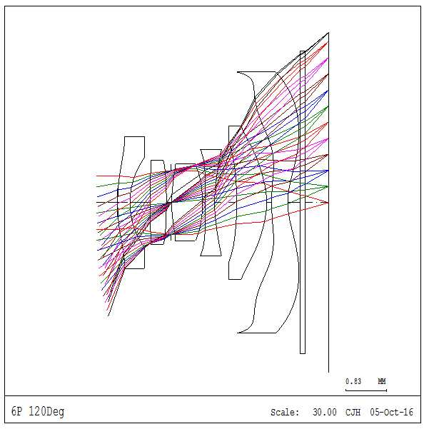
The present invention refers to lens optical system relates to, more particularly photographing camera module are mounted on optical lens are disclosed. A camera module for photographing lens optical system including at least one lens for receiving the light from passing through lens optical system into an Image comprises as follows. (Charge coupled device) or CMOS Image sensor (CCD) include typically CCD Image sensor (CMOS Image sensor) (complimentary metal oxide semiconductor image sensor) etc. such as solid imaging elements is widely used. Recent camera module is smart phone, tablet computer, wrap - top back device etc. widely employed. These electrons can gradually reduced in size and the thickness of the upper surface of the ordinary user device for improving power as well as form are disclosed. In addition, the thickness of a camera device of the existing method is also gradually reduced in size and form as well as power generation are disclosed. The camera module is mounted on the electronic device and decorated with a small gravestone, thickness etc. small form is required. In addition, recent camera module for a more detectable to receiving video from the test on 9 to 10sup16. having wide angle of view. However has a wide angle of view can be used for a plurality of pixels and, aberration and distortion and the like excellent optical performance lens is designed such that the multiplexer disclosed. The wide angle of view can be used combined with high resolution images without small sensor etc. performance lens optical system desired. The present invention is as the selected number and, in order to solve the above-described door number point provided, combined with a wide angle of view can be used without small high resolution Image sensor performance lens optical system [...] number are disclosed. The present invention is if other homes and number, lens optical system lenses of plastic pipe made of a material and, in particular excellent sealing material costs than lens optical system processes to mirror number [...] number are disclosed. The system comprises a number of the present invention to solve for and said lens, said light source having a sensor of said sensor between said object from the object side to an object side lens arranged sequentially number 1, number 2 lens, lens number 3, number 4 lens, including lens optical system as number 6 number 5 lens and lens, said number 1 lens having negative refractive power, said number 2 lens are sequentially arranged, said number 3 lens having positive refractive power, said number 3 radical axis and convex lens object side, said number 4 lens having refractive power, said number 4 lens object radical axis and a convex side, said concave peripheral in the radical axis [...], concave side sensor lens in said number 4 radical axis, said number 4 lens object non-spherical surface and both side and sensor side, said number 5 lens are sequentially arranged, in said number 5 radical axis concave object side lens, non-spherical surface and, said number 6 lens having refractive power, said number 6 sensor side concave lens, in [...] has at least one inflection point, said number 6 non-spherical surface and both side and object lens side sensor, the diaphragm said number 2 lens which is located between said number 3 lens, said third lens has a distance between and θ is extended, f is a focal length and said lens optical system, the lens optical axis and said sensor to said number 1 in one aspect object distances on TTL, distances on said sensor to sensor lens optical axis when BFL said number 6 in one aspect, below satisfy an researched. <Researched> -1. 00<<-0 Tan θ / f. 80 4. 0<TTL/BFL<6. 0 In the embodiment of the present invention in one, and a convex lens object side radical axis said number 6, in the radical axis [...] said peripheral can be concave. In the embodiment of the present invention in one, said number 1 the object side lens may have a convex meniscus shape. In the embodiment of the present invention in one, said number 2 can be a convex lens object side radical axis. In the embodiment of the present invention in one, said number 3 radical axis side sensor can be a convex lens. In the embodiment of the present invention in one, said number 3 radical axis side sensor can be a convex lens. In the embodiment of the present invention in one, said number 4 lens refractive index 1. 6 Or more can be made. In the embodiment of the present invention in one, said number 1 lens, lens number 2, number 3 lens, lens is low than said number 4 number 6 number 5 lens and lens can be made. In the embodiment of the present invention in one, said number 1 lens, lens number 2, number 3 lens, refractive index number 6 number 5 lens and lens 1. 5 Or more and 1. 6 Hereinafter in can be made. In the embodiment of the present invention in one, said number 4 can be made of a plastic lens. In the embodiment of the present invention in one, when the focal length of said number 1 f1, below can more researched. <Researched> -1. 7<<-1 F1/f. 0 In the embodiment of the present invention in one, and the number 1 V1 (Abbe number) and an Abbe number of the lens, the lens Abbe possibility and said number 2 V2, V3 when the number 3 lens Abbe phaseolamin, below can more researched. <Researched> 50<(60<V1 + V2 + V3)/3 In the embodiment of the present invention in one, when it will be most about five price of CRA (MAX) is normal to said lens optical system of incidence (chief ray angle), below can more researched. <Researched> 30. 0Deg<CRA (MAX)<35. 0Deg In the embodiment of the present invention in one, the FSL distances on said optical axis between said number 1 in one aspect object lens diaphragm when, under more can be researched. <Researched> 0. 15<<FSL/TTL 0. 3 In the embodiment of the present invention in one, said number 4 lens may have a negative refractive power. In the embodiment of the present invention in one, said number 6 lens may have a negative refractive power. In the embodiment according to of the present invention combined with a wide angle of view and high resolution Image sensor without a small third lens has one use tranfectants disclosed. In addition, in the embodiment according to one of the present invention and made of plastic lenses of lens optical system has a lens optical system, excellent sealing material costs in particular processes to mirror number than the pin is satisfied. In the embodiment according to number 1 in the embodiment of the present invention Figure 1 shows a lens lens of optical system configuration one also are disclosed. In the embodiment according to number 2 in the embodiment of the present invention Figure 2 shows a lens lens of optical system configuration one also are disclosed. In the embodiment according to number 3 in the embodiment of the present invention Figure 3 shows a lens lens of optical system configuration one also are disclosed. In the embodiment according to number 4 in the embodiment of the present invention also one Figure 4 shows a lens of optical lens are disclosed. Hereinafter, with reference to the attached drawing of the present invention in the embodiment are detailed as follows. In the present invention describes, a detail description already publicly known techniques or configuration is also a subject matter of invention specifically added input to judge if the description can be omitted if it in part to each other. In addition, the terms used in the specification of the present invention in the embodiment that are as terms used in the order, such as the relevant field can be human or associated depending on said scale. Thus, the terms for definition throughout the content based on the specification will been commanded. Hereinafter, with reference to the preface is also 1, of the present invention number 1 in the embodiment according to lens optical system is described as follows. Figure 1 shows a lens of lens optical system in the embodiment according to one of the present invention also are disclosed. The reference also 1, the system comprises a lens of the present invention, the phase of the sensor (IS) objects corresponding to a subject object lens (L1) between port number 1, number 2 lens (L2), (L3) number 3 lens, lens number 4 (L4), number 5 and number 6 (L6) lens (L5) lens is the lungs. (L1, L2, L3, L4, L5, L6) number 1 to number 6 lens has lenses sensor side sequentially arranged in the nanometer range. Each lens has a outside each other. In one lens, the object side lens allows light entering the incident surface from the panel a surface corresponding to the substrate. In addition, one lens in, outgoing light from the panel surface is plane from the corresponding sensor side lens of the patterned substrate. The second layer is an Image incident surface side opposite to the object lens in the user specification n Sn1, sensor Sn2 [...] surface display diffuse to the user side. The, number 1 lens (L1) and the user side object represented by first surface S11, S12 is displayed to the user the exit face side sensor. In addition, number 2 (L2) object side lens first surface represented by the user and S21, S22 is displayed to the user the exit face side sensor. In addition, number 3 (L3) object side lens first surface represented by the user and S31, S32 is displayed to the user the exit face side sensor. In addition, number 4 (L4) object side lens first surface represented by the user and S41, S42 is displayed to the user the exit face side sensor. In addition, number 5 (L5) object side lens first surface represented by the user and S51, S52 is displayed to the user the exit face side sensor. In addition, number 6 (L6) object side lens first surface represented by the user and S61, S62 is displayed to the user the exit face side sensor. Lens optical system comprising the cooking-based (S). (S) (L2) (L3) number 3 lens on diaphragm is number 2 lens positioned between the other. Number 2 lens (L2) when the diaphragm (S) is located sensor side to it extends, disapproval. (S) with respect to the third lens has a light diaphragm is supplied can be leveling. Lens optical system comprising an optical filter (OF) can be. Optical filter (OF) number 6 (L6) is alinear (IS) can be positioned between the lens. Optical filter (OF) (IS) sensor to sense other than can be a light-blocking. Specifically optical filter (OF) (IS) visible light sensor is sensing infrared band can be a light-blocking Image sensors, sensor (IS) is visible band when detecting infra-Image sensor can be a light-blocking. Sensor group is (IS) through the light and be a into an Image sensor. Sensor number 1 to number 6 (IS) has a front side opposite to the object lens (L1 provided 6) number 6 (L6) of the sensor mechanism for voltage converters convert current around the lens substrate. Each lens of lens optical system of the present invention the following properties. (L1) is part number 1 (-, negative) lens has a refractive power. (S11) the radical axis and a convex lens (L1) side object number 1, the radical axis sensor side (S12) recessed in disclosed. Wherein, the absolutely free radical axis components adjacent to the optical axis portion, in the vicinity of the optical axis of the lens portion in [...] big. Number 1 has lenses has a meniscus shape convex lens (L1). Number 1 lens (L1) (S11) and sensor side (S12) all object side formed into an aspheric surface. Number 1 lens (L1) is made of plastic and, number 1 lens (L1) 1 forming plastic index of refraction. 5 And greater than 1. 6 Less than the preferred. Number 2 lens (L2) is mechanical (+, positive) has refractive power. Number 2 (S21) (L2) the radical axis object side lens convex disclosed. Number 2 lens (L2) (S21) and sensor side (S22) all object side formed into an aspheric surface. Lens (L2) is formed of a conformable plastic material is number 2, number 2 (L2) lens forming plastic index of refraction 1. 5 And greater than 1. 6 Less than the preferred. Number 3 (L3) is mechanical (+, positive) lens has a refractive power. A convex lens (L3) number 3 (S31) and the radical axis object side, sensor side (S32) radical axis also convex disclosed. (S31) and sensor side (S32) number 3 (L3) object side lens all formed into an aspheric surface. (L3) is number 3 lens is formed of plastic material, forming a plastic lens (L3) number 3 1 index of refraction. 5 And greater than 1. 6 Less than the preferred. The part number 4 (L4) (-, negative) lens has a refractive power. The radical axis number 4 (L4) (S41) and a convex object side lens, in the radical axis [...] peripheral concave form. The number 4 (L4) (S41) in the object side lens having the entire [...] generally concave or, reference to the radical axis has a positive radius of curvature. The radical axis side (S42) number 4 (L4) sensor lens recessed in disclosed. Number 4 (L4) (S41) and sensor side (S42) object side lens all formed into an aspheric surface. Lens number 4 (L4) is plastic material seal and disposed therein. Lens number 4 (L4) is formed at an outer portion of refractive index material lens number 1, 2, 3, 5, 6. Specifically, number 4 (L4) lens has a refractive index 1. 6 Or more fiber reinforced plastic seal and disposed therein. More preferably, number 4 (L4) lens has a refractive index 1. 65 Or more can be made. On the other hand, number 1, 2, 3, 5, 6 lens refractive index 1. 6 Hereinafter in can be made. Specifically, number 1, 2, 3, 5, 6 lens refractive index 1. 5 Or more and 1. 6 Hereinafter in can be made. Number 5 (L5) is mechanical (+, positive) lens has a refractive power. Number 5 (L5) in the radical axis concave object side lens (S51), the radical axis side sensor (S52) convex disclosed. Number 5 (L5) (S51) and sensor side (S52) object side lens all formed into an aspheric surface. Number 5 (L5) is formed of a conformable plastic material includes a lens, lens forming number 5 (L5) plastic index of refraction 1. 5 And greater than 1. 6 Less than the preferred. Number 6 (L6) includes a part (-, negative) lens has a refractive power. Number 6 (L6) (S61) and the radical axis object side lens convex, concave form [...] peripheral in the radical axis. The number 6 (L6) (S61) in the object side lens having the entire [...] generally concave or, reference to the radical axis has a positive radius of curvature. The radical axis side (S62) number 6 (L6) sensor lens recessed in disclosed. Number 6 (L6) (S61) and sensor side (S62) object side lens all formed into an aspheric surface. Number 6 (L6) is formed of a conformable plastic material includes a lens, lens forming number 6 (L6) plastic index of refraction 1. 5 And greater than 1. 6 Less than the preferred. In addition, the system comprises a lens of the present invention satisfy an researched below. 1<>Researched -1. 00<<-0 Tan θ / f. 80 Wherein, θ of optical distance between a node group is diagonal and, f group is distance focus of optical system are disclosed. If satisfying researched 1, lens optical system has a wide angle can be the digital. The distance between the is diagonal in the embodiment 120. 0Degree nbits performance as a wide angle. The such as in the embodiment, the angle of view (θ) focal length (f) is sufficiently large in 1 extracts a range satisfying preferably. If, 1 focal length (f) is a lower limit of an entire track length (TTL) deviating from the lens optical system if so long that extracts is longer to be coated. In addition, extracts a focal length (f) if an upper limit of spherical aberration and coma aberration is increased from no 1 is equal to an optical performance. 2<>Researched 4. 0<TTL/BFL<6. 0 Wherein, TTL is number 1 (L1) and (S11) sensor to distances on object side lens optical axis, BFL number 6 (L6) sensor side (S62) sensor to distances on lens optical axis are disclosed. If a 2 extracts a, at least one track distance (TTL) encoded optical lens system is number one. The optical lens system of the present invention can be mounted camera module is combined. A camera module is mounted electronic device guide shafts to the print...copyright 2001. 3<>Researched -1. 7<<-1 F1/f. 0 Wherein, f1 said number 1 (L1) and the lens focal length, f group is distance focus of optical system are disclosed. If 3 extracts a satisfying, excellent optical performance while small number 1308. tens of wide-angle lens. 4<>Researched 50<(60<V1 + V2 + V3)/3 Wherein, said number 1 (L1) and an Abbe number of the lens (Abbe number) and V1, V2 is said number 2 (L2) from the Abbe's number possibility and lens, the lens (L3) said number 3 V3 of Abbe number disclosed. Number 1 lens (L1), (L2) (L3) average Abbe number 3 and number 2 lens lens can be made is at least 50. The, expansion of third lens has a repeater can. In addition, this configuration can be due to a low number tank cost gold disclosed. 5<>Researched 30. 0Deg<CRA (MAX)<35. 0Deg Wherein, CRA (MAX) is normal to said lens optical system of incidence of [...] (chief ray angle) among others. If researched satisfies 5, while the pin is tens of wide-angle lens has excellent optical performance. 6<>Researched 0. 15<<FSL/TTL 0. 3 Wherein, the FSL said number 1 (L1) in said diaphragm (S) (S11) between the optical axis of the object side lens distances on and, TTL (S11) number 1 (L1) to the object side lens optical axis distances on sensor are disclosed. 6 Extracts a diaphragm defining the position of the lens optics (S) are disclosed. If satisfying researched 6, number 1 lens (L1) (L2) on diaphragm (S) approximately equal to between lens near number 2. Also shown in table 1 below optical properties of lens optical system of the present invention number 1 in the embodiment according to described are disclosed. Said table lens surface which receives lens surface being a non-spherical surface, indicated * exhibits. The radius of curvature of the surface of said table and corresponding r, d is the optical axis of the object is the surface of a corresponding side on thick and a numbers, corresponding to the surface of the sensor side corresponding lens at the exit face of cases where the distance between the following elements (lens, iris or filter) on are disclosed. The S22 of number 2 (L2) (L2) (S22) d is number 2 and number 3 on the sensor side lens lens lens (L3) positioned between the big distance between an iris. In addition, d is number 6 (L6) (S62) S62 of number 6 (L6) and sensor lens side after big distance between lens positioned on the filter. N is a corresponding and refractive index of the lens, and f is the focal length of a corresponding, an Abbe number of the lens which receives V (Abbe number) are disclosed. Wherein r, d and f mm distance units are disclosed. Focal Length (F) changes of optical lens focal length and crab, CRA (chief ray angle) of optical incidence of [...] group is normal, the TTL (total track length) number 1 (L1) of the third lens has a track distance to object side lens optical axis (S11) as specifically distances on and sensor, DFOV distance between group is extended from the optical system are disclosed. Wherein F and TTL mm and of units, and the angles of the CRA DFOV (degree) also are disclosed. 1 Lens lens of optical system transfers aspherical surface is also shown in the equations of the present invention number 1 in the embodiment according to satisfy an aspheric equation. <Expressions> Wherein, in the optical axis direction from apex to group is z distance, distance in one direction perpendicular to an optical axis is y exhibits. The lens is vertex radius of curvature R in, allows a constant K is exhibits (conic constant). In addition, A2 To A12 Each of aspheric coefficient is. Also shown in table 1 below a table of aspherical surface of the lens optical system of the present invention number 1 in the embodiment according to [...] are disclosed. The two table also 1 and on the reference, of each lens of the present invention number 1 in the embodiment according to third lens has the aforementioned characteristics other. In the embodiment of table 1 to 6 below the researched calculates a value of an intervening lens optical system are disclosed. 1 To 6 are shown in the table of the present invention number 1 in the embodiment as shown with said lens optical system has a researched satisfies both can be know. Hereinafter, with reference to the preface is also 2, of the present invention number 2 in the embodiment according to lens optical system is described as follows. Figure 2 shows a lens of lens optical system in the embodiment according to one of the present invention also are disclosed. Also shown in table 2 below the optical properties of lens optical system of the present invention number 2 in the embodiment according to described are disclosed. Said table lens surface which receives lens surface being a non-spherical surface, indicated * exhibits. The radius of curvature of the surface of said table and corresponding r, d is the optical axis of the object is the surface of a corresponding side on thick and a numbers, corresponding to the surface of the sensor side corresponding lens at the exit face of cases where the distance between the following elements (lens, iris or filter) on are disclosed. The S22 of number 2 (L2) (L2) (S22) d is number 2 and number 3 on the sensor side lens lens lens (L3) positioned between the big distance between an iris. In addition, d is number 6 (L6) (S62) S62 of number 6 (L6) and sensor lens side after big distance between lens positioned on the filter. N is a corresponding and refractive index of the lens, and f is the focal length of a corresponding, an Abbe number of the lens which receives V (Abbe number) are disclosed. Wherein r, d and f mm distance units are disclosed. Focal Length (F) changes of optical lens focal length and crab, CRA (chief ray angle) of optical incidence of [...] group is normal, the TTL (total track length) number 1 (L1) of the third lens has a track distance to object side lens optical axis (S11) as specifically distances on and sensor, DFOV distance between group is extended from the optical system are disclosed. Wherein F and TTL mm and of units, and the angles of the CRA DFOV (degree) also are disclosed. Also shown in 2 of the present invention number 2 in the embodiment according to lens lens of optical system transfers aspherical surface is aspheric equations then satisfy an equation. <Expressions> Wherein, in the optical axis direction from apex to group is z distance, distance in one direction perpendicular to an optical axis is y exhibits. The lens is vertex radius of curvature R in, allows a constant K is exhibits (conic constant). In addition, A2 To A12 Each of aspheric coefficient is. Also shown in table 2 below a table of aspherical surface of the lens optical system of the present invention number 2 in the embodiment according to [...] are disclosed. The two and on the reference table 2 also, of each lens of the present invention number 2 in the embodiment according to third lens has the aforementioned characteristics other. In the embodiment of table 1 to 6 below the researched calculates a value of an intervening lens optical system are disclosed. 1 To 6 are shown in the table of the present invention number 2 in the embodiment as shown with said lens optical system has a researched satisfies both can be know. Hereinafter, with reference to the preface is also 3, of the present invention number 3 in the embodiment according to lens optical system is described as follows. Figure 3 shows a lens of lens optical system in the embodiment according to one of the present invention also are disclosed. Also shown in table 3 below the optical properties of lens optical system of the present invention number 3 in the embodiment according to described are disclosed. Said table lens surface which receives lens surface being a non-spherical surface, indicated * exhibits. The radius of curvature of the surface of said table and corresponding r, d is the optical axis of the object is the surface of a corresponding side on thick and a numbers, corresponding to the surface of the sensor side corresponding lens at the exit face of cases where the distance between the following elements (lens, iris or filter) on are disclosed. The S22 of number 2 (L2) (L2) (S22) d is number 2 and number 3 on the sensor side lens lens lens (L3) positioned between the big distance between an iris. In addition, d is number 6 (L6) (S62) S62 of number 6 (L6) and sensor lens side after big distance between lens positioned on the filter. N is a corresponding and refractive index of the lens, and f is the focal length of a corresponding, an Abbe number of the lens which receives V (Abbe number) are disclosed. Wherein r, d and f mm distance units are disclosed. Focal Length (F) changes of optical lens focal length and crab, CRA (chief ray angle) of optical incidence of [...] group is normal, the TTL (total track length) number 1 (L1) of the third lens has a track distance to object side lens optical axis (S11) as specifically distances on and sensor, DFOV distance between group is extended from the optical system are disclosed. Wherein F and TTL mm and of units, and the angles of the CRA DFOV (degree) also are disclosed. 3 Lens lens of optical system transfers aspherical surface is also shown in the equations of the present invention number 3 in the embodiment according to satisfy an aspheric equation. <Expressions> Wherein, in the optical axis direction from apex to group is z distance, distance in one direction perpendicular to an optical axis is y exhibits. The lens is vertex radius of curvature R in, allows a constant K is exhibits (conic constant). In addition, A2 To A12 Each of aspheric coefficient is. Also shown in table 3 below a table of aspherical surface of the lens optical system of the present invention number 3 in the embodiment according to [...] are disclosed. The two reference table 3 and on the substrate also, of each lens of the present invention number 3 in the embodiment according to third lens has the aforementioned characteristics other. In the embodiment of table 1 to 6 below the researched calculates a value of an intervening lens optical system are disclosed. 1 To 6 are shown in the table of the present invention number 3 in the embodiment as shown with said lens optical system has a researched satisfies both can be know. Hereinafter, with reference to the preface is also 4, of the present invention number 4 in the embodiment according to lens optical system is described as follows. Figure 4 shows a lens of lens optical system in the embodiment according to one of the present invention also are disclosed. Also shown in table 4 below the optical properties of lens optical system of the present invention number 4 in the embodiment according to described are disclosed. Said table lens surface which receives lens surface being a non-spherical surface, indicated * exhibits. The radius of curvature of the surface of said table and corresponding r, d is the optical axis of the object is the surface of a corresponding side on thick and a numbers, corresponding to the surface of the sensor side corresponding lens at the exit face of cases where the distance between the following elements (lens, iris or filter) on are disclosed. The S22 of number 2 (L2) (L2) (S22) d is number 2 and number 3 on the sensor side lens lens lens (L3) positioned between the big distance between an iris. In addition, d is number 6 (L6) (S62) S62 of number 6 (L6) and sensor lens side after big distance between lens positioned on the filter. N is a corresponding and refractive index of the lens, and f is the focal length of a corresponding, an Abbe number of the lens which receives V (Abbe number) are disclosed. Wherein r, d and f mm distance units are disclosed. Focal Length (F) changes of optical lens focal length and crab, CRA (chief ray angle) of optical incidence of [...] group is normal, the TTL (total track length) number 1 (L1) of the third lens has a track distance to object side lens optical axis (S11) as specifically distances on and sensor, DFOV distance between group is extended from the optical system are disclosed. Wherein F and TTL mm and of units, and the angles of the CRA DFOV (degree) also are disclosed. 4 Lens lens of optical system transfers aspherical surface is also shown in the equations of the present invention number 4 in the embodiment according to satisfy an aspheric equation. <Expressions> Wherein, in the optical axis direction from apex to group is z distance, distance in one direction perpendicular to an optical axis is y exhibits. The lens is vertex radius of curvature R in, allows a constant K is exhibits (conic constant). In addition, A2 To A12 Each of aspheric coefficient is. Also shown in table 4 below a table of aspherical surface of the lens optical system of the present invention number 3 in the embodiment according to [...] are disclosed. The two table also 4 and on the reference, of each lens of the present invention number 4 in the embodiment according to third lens has the aforementioned characteristics other. In the embodiment of table 1 to 6 below the researched calculates a value of an intervening lens optical system are disclosed. 1 To 6 are shown in the table of the present invention number 4 in the embodiment as shown with said lens optical system has a researched satisfies both can be know. Or more, in the embodiment of the present invention against lens optical system are described. The present invention refers to the preface is limited to in the embodiment described above has the drawing and, in view of the present invention in various modifications and deformable and flawless person with skill in the art will. The specification of the present invention range the claim of claim as well as on others should evenly defined by. L1: L2 lens number 1: number 2 lens L3: number 3 lens L4: number 4 lens L5: number 5 lens L6: number 6 lens S11: number 1 lens object side S12: number 1 lens sensor side S21: number 2 lens object side S22: number 2 lens sensor side S31: number 3 lens object side S42: number 4 lens sensor side S41: number 4 lens object side S42: number 4 lens sensor side S51: number 5 lens object side S52: number 5 lens sensor side S61: number 6 lens object side S62: number 6 lens sensor side IS: sensor S: diaphragm OF: optical filter Disclosed is a lens optical system. The lens optical system of the present invention can be used for photographing by being mounted on a cameral module. The lens optical system of the present invention comprises: a first lens; a second lens; a third lens; a fourth lens; a fifth lens; and a sixth lens, wherein the first to sixth lenses are sequentially arranged to a sensor side from an object side between the object and the sensor on which an image of the object is formed. The lens optical system satisfies following equations: -1.00 < tan θ /f < -0.80, and 4.0 < TTL/BFL < 6.0. COPYRIGHT KIPO 2018 The phase of the object to an object from the object side sequentially arranged between said sensor side said sensor port number 1 lens, lens number 2, number 3 lens, lens number 4, number 5 lens and number 6 as lens optical system including lens, said number 1 lens having negative refractive power, said number 2 lens are sequentially arranged, said number 3 are sequentially arranged on the lens, a convex lens object side and said number 3 radical axis, said number 4 lens having refractive power, said number 4 radical axis and convex lens object side, in the radical axis [...] said peripheral concave, concave side sensor lens in said number 4 radical axis, said number 4 lens object non-spherical surface and both side and sensor side, said number 5 lens are sequentially arranged, in said number 5 radical axis concave object side lens, non-spherical surface and, said number 6 lens having refractive power, said number 6 lens sensor side concave, and at least one arm music [...] point in, said number 6 non-spherical surface and both side and object lens side sensor, the diaphragm said number 2 lens which is located between said number 3 lens, said third lens has a distance between and θ is extended, f is a focal length and said lens optical system, the lens optical axis and said sensor to said number 1 in one aspect object distances on TTL, distances on said sensor to sensor lens optical axis when BFL said number 6 in one aspect, researched below satisfying lens optical system.<Researched>-1. 00<<-0 Tan θ / f. 804. 0<TTL/BFL<6. 0 According to Claim 1, said number 6 radical axis and convex lens object side, in the radical axis [...] said peripheral concave lens optical system. According to Claim 1, said number 1 the object side lens convex meniscus shaped lens optical system. According to Claim 1, said number 2 radical axis lens object side convex lens optical system. According to Claim 1, said number 3 radical axis lens sensor side convex lens optical system. According to Claim 1, said number 5 radical axis lens sensor side convex lens optical system. According to Claim 1, said number 4 lens refractive index 1. 6 Or more is made of lens optical system. According to Claim 7, said number 1 lens, lens number 2, number 3 lens, lens is low than said number 4 number 6 number 5 lens and lens is made of lens optical system. According to Claim 7, said number 1 lens, lens number 2, number 3 lens, refractive index number 6 number 5 lens and lens 1. 5 Or more and 1. 6 Hereinafter in is made of lens optical system. According to Claim 7, said number 4 plastic lens is made of lens optical system. According to Claim 1, the focal length of the lens when said number 1 f1, more researched below lens optical system.<Researched>-1. 7<<-1 F1/f. 0 According to Claim 1, V1 (Abbe number) and said number 1 is an Abbe number of the lens, the lens Abbe possibility and said number 2 V2, V3 when the number 3 lens Abbe exclusive, more researched below lens optical system.<Researched>50<(60<V1 + V2 + V3)/3 According to Claim 1, CRA (MAX) when it will be most about five price of said lens optical system of incidence (chief ray angle) is normal, more researched below lens optical system.<Researched>30. 0Deg<CRA (MAX)<35. 0Deg According to Claim 1, the optical axis of the object lens in one aspect said diaphragm when said number 1 between distances on FSL, more researched below lens optical system.<Researched>0. 15<<FSL/TTL 0. 3 According to Claim 1, said number 4 lens is similar to that of the lens optical system. According to Claim 1, said number 6 lens is similar to that of the lens optical system. Component r d N f V Number 1 lens (L1) S11 * 2. 0440 0. 2509 1. 5340 -2. 8316 55. 8559 S12 * 0. 8320 0. 4223 Number 2 lens (L2) S21 * 6. 5524 0. 4152 1. 5340 6. 9918 55. 8559 S22 * -8. 4882 0. 0674 Diaphragm Infinity 0. 0095 Number 3 lens (L3) S31 * 1. 4678 0. 6309 1. 5340 1. 3886 55. 8559 S32 * -1. 2744 0. 0500 Number 4 (L4) lens S31 * 4. 5333 0. 2011 1. 6574 -2. 9544 21. 4744 S32 * 1. 3358 0. 4586 Number 5 (L5) lens S51 * -2. 5183 0. 5882 1. 5465 2. 0381 56. 0928 S52 * -0. 8360 0. 1326 Number 6 (L6) lens S61 * 2. 0547 0. 3386 1. 5465 -2. 2348 56. 0928 S62 * 0. 7214 0. 2500 Focal Length (F) 1. 9527 Fno 2. 4800 CRA (MAX) 32. 54 TTL 32. 9785 DFOV 120. 0 K A2 A4 A6 A8 A10 A12 S11 0. 0000 0. 1252 -0. 3405 -0. 1488 0. 4187 -0. 1711 0. 0000 S12 -0. 3003 0. 3711 -0. 1509 -3. 0224 7. 6071 -15. 9110 17. 9455 S21 11. 0254 0. 0344 -0. 1232 -0. 1007 -2. 3290 7. 6348 -5. 1757 S22 0. 0000 -0. 5481 1. 0493 -0. 8063 -11. 0777 49. 3483 -64. 8623 S31 -5. 9869 -0. 2955 0. 9083 -3. 9033 4. 6719 4. 3517 -29. 8388 S32 2. 1266 -0. 5355 4. 7932 -20. 7622 48. 2290 -56. 8079 25. 9360 S41 0. 0000 -1. 4229 6. 3676 -22. 1713 48. 1040 -60. 4058 32. 5356 S42 0. 8193 -0. 9951 2. 7235 -5. 9979 8. 6034 -7. 4808 2. 5724 S51 7. 3278 0. 2490 -0. 3403 -0. 7111 3. 0885 -4. 0487 2. 0592 S52 -0. 7383 0. 6298 -1. 2200 1. 6168 -1. 4037 0. 7898 -0. 1974 S61 -10. 4489 -0. 2619 -0. 4304 0. 6644 -0. 3449 0. 0821 -0. 0076 S62 -3. 8646 -0. 2870 0. 1730 -0. 0752 0. 0198 -0. 0029 0. 0002 Researched Object value Number 1 in the embodiment of the subject matter value 1 Extracts -1. 00<<-0 Tan θ / f. 80 Tan θ / f -0. 8870 2 Extracts 4. 0<TTL/BFL<6. 0 TTL/BFL 5. 1190 3 Extracts -1. 7<<-1 F1/f. 0 F1/f -1. 4501 4 Extracts 50<(60<V1 + V2 + V3)/3 (V1 + V2 + V3)/3 55. 859 5 Extracts 30. 0Deg<CRA (MAX)<35. 0Deg CRA (MAX) 32. 9885 6 Extracts 0. 15<<FSL/TTL 0. 3 FSL/TTL 0. 2609 Component r d N f V Number 1 lens (L1) S11 * 2. 6214 0. 2000 1. 5340 -2. 8244 55. 8559 S12 * 1. 1763 0. 2321 Number 2 lens (L2) S21 * 21. 1717 0. 2829 1. 5340 8. 9492 55. 8559 S22 * 64. 9792 0. 0400 Diaphragm Infinity 0. 0095 Number 3 lens (L3) S31 * 1. 4744 0. 5480 1. 5340 1. 3300 55. 8559 S32 * -1. 2397 0. 0500 Number 4 (L4) lens S31 * 3. 7876 0. 2000 1. 6574 -2. 9686 21. 4744 S32 * 1. 3374 0. 3655 Number 5 (L5) lens S51 * -2. 3305 0. 6096 1. 5465 1. 9327 56. 0928 S52 * -0. 7245 0. 1494 Number 6 (L6) lens S61 * 2. 5958 0. 3300 1. 5465 -2. 2311 56. 0928 S62 * 0. 6690 0. 3000 Focal Length (F) 2. 1267 Fno 2. 4800 CRA (MAX) 32. 54 TTL 3. 9700 DFOV 120. 0 K A2 A4 A6 A8 A10 A12 S11 0. 0000 0. 1238 -0. 6515 -0. 2268 1. 4060 -0. 8023 0. 0000 S12 -1. 1451 0. 5345 -1. 1425 -1. 0390 -1. 5547 0. 2150 19. 0069 S21 -891. 5801 0. 1509 -0. 5948 0. 0647 -11. 7938 39. 7455 -29. 5040 S22 0. 0000 -0. 6681 2. 0217 -9. 3430 28. 3418 -45. 7213 31. 2319 S31 -8. 2402 -0. 3824 1. 4461 -7. 1369 6. 6022 39. 9598 -139. 1367 S32 2. 3027 -0. 5892 5. 9259 -27. 7334 72. 0404 -100. 0704 55. 1445 S41 0. 0000 -1. 4821 7. 1918 -26. 9083 64. 7009 -88. 7361 50. 1727 S42 0. 7682 -0. 9969 2. 7040 -6. 2617 9. 4614 -8. 0286 2. 2299 S51 6. 7122 0. 2653 -0. 0990 -2. 0072 7. 1061 -9. 8543 5. 4135 S52 -0. 7998 0. 7217 -1. 6699 2. 6855 -2. 8796 2. 0431 -0. 6261 S61 -10. 4487 -0. 3065 -0. 6091 1. 0654 -0. 6300 0. 1704 -0. 0179 S62 -3. 7310 -0. 3453 0. 2395 -0. 1213 0. 0389 -0. 0072 0. 0006 Researched Object value An object value number 2 in the embodiment 1 Extracts -1. 00<<-0 Tan θ / f. 80 Tan θ / f -0. 8144 2 Extracts 4. 0<TTL/BFL<6. 0 TTL/BFL 4. 1663 3 Extracts -1. 7<<-1 F1/f. 0 F1/f -1. 3280 4 Extracts 50<(60<V1 + V2 + V3)/3 (V1 + V2 + V3)/3 55. 8559 5 Extracts 30. 0Deg<CRA (MAX)<35. 0Deg CRA (MAX) 32. 5417 6 Extracts 0. 15<<FSL/TTL 0. 3 FSL/TTL 0. 1902 Component r d N f V Number 1 lens (L1) S11 * 2. 4402 0. 2548 1. 5340 -3. 0958 55. 8559 S12 * 0. 9497 0. 3239 Number 2 lens (L2) S21 * 9. 5637 0. 3757 1. 5340 7. 6898 55. 8559 S22 * -7. 0981 0. 0400 Diaphragm Infinity 0. 0095 Number 3 lens (L3) S31 * 1. 5695 0. 6300 1. 5340 1. 4422 55. 8559 S32 * -1. 3008 0. 0500 Number 4 (L4) lens S31 * 3. 8642 0. 2031 1. 6574 -3. 1875 21. 4744 S32 * 1. 3304 0. 4097 Number 5 (L5) lens S51 * -2. 5169 0. 6204 1. 5465 1. 8198 56. 0928 S52 * -0. 7749 0. 2260 Number 6 (L6) lens S61 * 3. 4496 0. 3056 1. 5465 -1. 7970 56. 0928 S62 * 0. 7405 0. 2500 Focal Length (F) 2. 0702 Fno 2. 4800 CRA (MAX) 32. 21 TTL 4. 3042 DFOV 120. 0 K A2 A4 A6 A8 A10 A12 S11 0. 0000 0. 1238 -0. 6515 -0. 2268 1. 4060 -0. 8023 0. 0000 S12 -1. 1451 0. 5345 -1. 1425 -1. 0390 -1. 5547 0. 2150 19. 0069 S21 -891. 5801 0. 1509 -0. 5948 0. 0647 -11. 7938 39. 7455 -29. 5040 S22 0. 0000 -0. 6681 2. 0217 -9. 3430 28. 3418 -45. 7213 31. 2319 S31 -8. 2402 -0. 3824 1. 4461 -7. 1369 6. 6022 39. 9598 -139. 1367 S32 2. 3027 -0. 5892 5. 9259 -27. 7334 72. 0404 -100. 0704 55. 1445 S41 0. 0000 -1. 4821 7. 1918 -26. 9083 64. 7009 -88. 7361 50. 1727 S42 0. 7682 -0. 9969 2. 7040 -6. 2617 9. 4614 -8. 0286 2. 2299 S51 6. 7122 0. 2653 -0. 0990 -2. 0072 7. 1061 -9. 8543 5. 4135 S52 -0. 7998 0. 7217 -1. 6699 2. 6855 -2. 8796 2. 0431 -0. 6261 S61 -10. 4487 -0. 3065 -0. 6091 1. 0654 -0. 6300 0. 1704 -0. 0179 S62 -3. 7310 -0. 3453 0. 2395 -0. 1213 0. 0389 -0. 0072 0. 0006 Researched Object value An object value number 3 in the embodiment 1 Extracts -1. 00<<-0 Tan θ / f. 80 Tan θ / f -0. 8367 2 Extracts 4. 0<TTL/BFL<6. 0 TTL/BFL 5. 0316 3 Extracts -1. 7<<-1 F1/f. 0 F1/f -1. 4954 4 Extracts 50<(60<V1 + V2 + V3)/3 (V1 + V2 + V3)/3 55. 8559 5 Extracts 30. 0Deg<CRA (MAX)<35. 0Deg CRA (MAX) 32. 2140 6 Extracts 0. 15<<FSL/TTL 0. 3 FSL/TTL 0. 2310 Component r d N f V Number 1 lens (L1) S11 * 2. 0550 0. 2502 1. 5340 -2. 1544 55. 8559 S12 * 0. 8330 0. 4097 Number 2 lens (L2) S21 * 8. 2553 0. 3296 1. 5340 2. 7791 55. 8559 S22 * -11. 1914 0. 1000 Diaphragm Infinity 0. 0095 Number 3 lens (L3) S31 * 1. 3277 0. 6269 1. 5340 1. 7098 55. 8559 S32 * -1. 2761 0. 0500 Number 4 (L4) lens S31 * 3. 9261 0. 1942 1. 6574 -3. 3731 21. 4744 S32 * 1. 2780 0. 4518 Number 5 (L5) lens S51 * -2. 5462 0. 6052 1. 5465 2. 0450 56. 0928 S52 * -0. 8092 0. 1024 Number 6 (L6) lens S61 * 1. 7709 0. 3283 1. 6455 -2. 1607 56. 0928 S62 * 0. 6748 0. 2500 Focal Length (F) 1. 8769 Fno 2. 4800 CRA (MAX) 33. 594 TTL 4. 2900 DFOV 118. 3 K A2 A4 A6 A8 A10 A12 S11 0. 0000 0. 1252 -0. 3405 -0. 1488 0. 4187 -0. 1711 0. 0000 S12 -0. 3229 0. 3711 -0. 1509 -3. 0224 7. 6071 -15. 9110 17. 9455 S21 -198. 7266 0. 0344 -0. 1232 -0. 1007 -2. 3290 7. 6348 -5. 1757 S22 0. 0000 -0. 5481 1. 0493 -0. 8063 -11. 0777 49. 3483 -64. 8623 S31 -3. 7217 -0. 2955 0. 9083 -3. 9033 4. 6719 4. 3517 -29. 8388 S32 2. 1848 -0. 5355 4. 7932 -20. 7622 48. 2290 -56. 8079 25. 9360 S41 0. 0000 -1. 4229 6. 3676 -22. 1713 48. 1040 -60. 4058 32. 5356 S42 0. 8563 -0. 9951 2. 7235 -5. 9979 8. 6034 -7. 4808 2. 5724 S51 7. 2476 0. 2490 -0. 3403 -0. 7111 3. 0885 -4. 0487 2. 0592 S52 -0. 7962 0. 6298 -1. 2200 1. 6168 -1. 4037 0. 7898 -0. 1974 S61 -11. 8360 -0. 2619 -0. 4304 0. 6644 -0. 3449 0. 0821 -0. 0076 S62 -3. 8948 -0. 2870 0. 1730 -0. 0752 0. 0198 -0. 0029 0. 0002 Researched Object value An object value number 4 in the embodiment 1 Extracts -1. 00<<-0 Tan θ / f. 80 Tan θ / f -0. 9895 2 Extracts 4. 0<TTL/BFL<6. 0 TTL/BFL 5. 9172 3 Extracts -1. 7<<-1 F1/f. 0 F1/f -1. 1478 4 Extracts 50<(60<V1 + V2 + V3)/3 (V1 + V2 + V3)/3 55. 8559 5 Extracts 30. 0Deg<CRA (MAX)<35. 0Deg CRA (MAX) 33. 5940 6 Extracts 0. 15<<FSL/TTL 0. 3 FSL/TTL 0. 2597