APPARATUS FOR FIXING CORNER BARRIER OF CARGO TANK
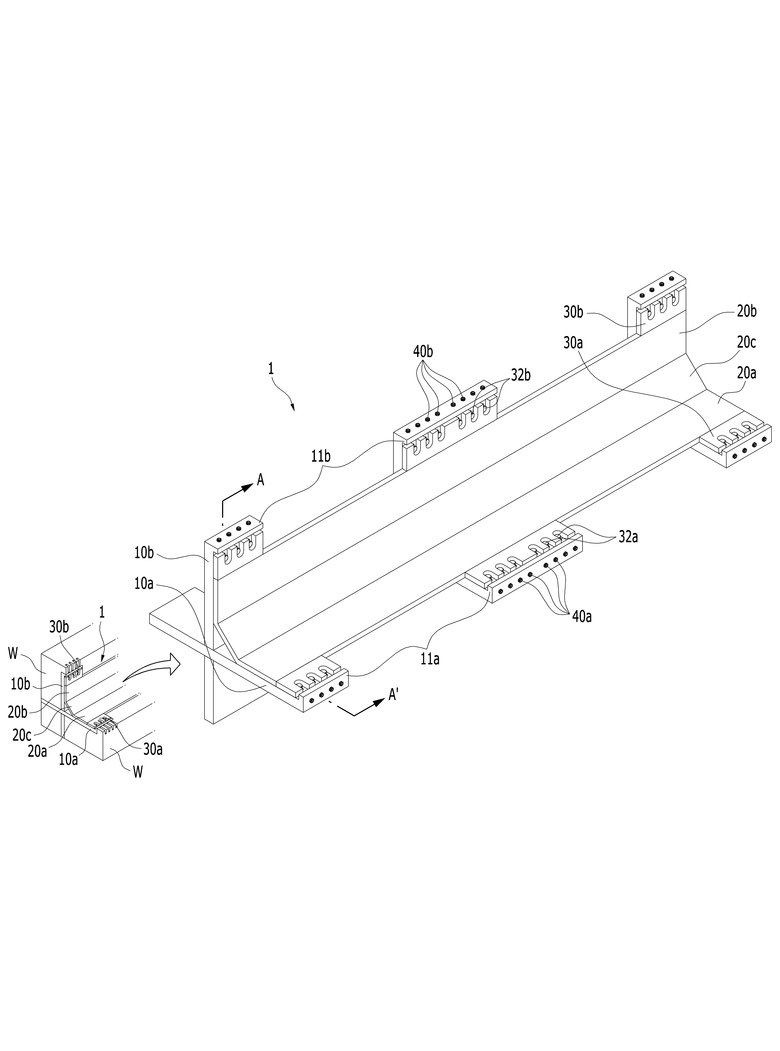
The present invention refers to insulation panel corner barrier fixing device relates to search, when gap is arranged at a corner of the LNG carrier is provided which is formed on the for hereinafter, by fixed device exposed to the barrier between the insulation panel corner portion fixed in height for absorbing the fixed at a barrier device are disclosed. Generally, cryogenic fluid such as liquefied natural gas and LNG carrier ship's carrying the multilayer barrier to the source including a barrier 1 difference barrier and 2 difference 2000. Barrier structure is exposed to a resin sealing wall play a role, are composed by same additional leakage pipe joint. I.e., 1 2 difference even if leakage by leakage of liquid cryogenic path difference barrier diffusion of patterned to form a barrier to prevent leakage can be diffused throughout the ship are disclosed. However, multilayer barrier structure layer even if the spread of this leakage, LNG is dry during wave operators such as hull such as a deformed by the interior flow from external shocks or avoid to tame. If liquefied natural gas is breakers, impact load and stress (stress) barrier delivery generated by breakers to be coated. For this reason, insulation panel of the corner stress time of shock load LNG carrier from one side must be structurally configured to 2000. To this end insulation panel of corner parts on which a corner plate causing the barrier structure, the barrier of the existing method and combined corner plate barrier groove so that the completely formed to conform to, a center hull barrier formed on the corner plates present invention cannot be door number flow tides. Thus, the external force to the hull by deformation of barrier formed on the corner portion is easily installed even in the center as well as, corner barrier can be positively secured to the securing means has been required. The technical objectives of this invention is, even if the gap is formed on the insulation panel of corner portion forms a barrier can be installed for hereinafter, a barrier device fixed to the photoresist pattern is fixed to cancel the fixed barrier when incorporated between the device and a fixed device number LNG carrier corner barrier gaps are disclosed. Technical number are not in yet another technique of the present invention mentioned above and below may be specific number are clearly understand one skilled from the substrate are disclosed. For LNG carrier according to an embodiment of the present invention achieve technical barrier device is fixed number and said corner, a corner of the ship cargo window of horizontal barrier pivotally mounted number 1, combined cross said number 1, number 2 said corner portion in the vertical direction is provided, each abutting corner at the loader has a number 1 number 2, number 1 plate contact number 1, number 2 number 2 plate contact , number 1 number 2 plate connecting plate including corner member number 3 plate, coupled to said number 1 horizontal direction, said number 1 plate by pressing the adjusting member and securing said number 1 number 1, said number 2 coupled movably in a vertical direction, said number 2 plate by pressing the adjusting member and securing said number 2 number 2, said number 1 junction absence screwed through at least one horizontal direction and an adjusting screw elements said number 1 and number 1, and said number 2 junction absence screwed through at least one vertical direction and an adjusting screw elements said number 2 and number 2 without using a tool. Said number 1 plate end said number 1 control member inserted into the stepped portion formed between said number 1 number 1, said number 2 plate end of the adjusting member inserted between said number 2 said number 2 number 2 can be stepped portion. Junction absence number 1 support and vertical end that engages said number 1, number 2 that engages said number 2 junction absence end further comprising a horizontal support, said number 1 through the number 1 support said number 1 covers the control member and an adjusting screw, an adjusting screw through said number 2 control member can be in contact with the number 2 support said number 2. Said number 1 and said number 2 control member touching the indented inwards in relation to each said number 2 junction absence said number 1 control member further includes a fixing groove each, said number 1 and an adjusting screw and said adjusting member and said number 2 an adjustment member is inserted into said number 1 and an adjusting screw is provided with a fixing groove by said number 2 travelling inside can be further comprises retaining grooves respectively formed in said. Said number 1 and arranged apart from each other along said number 1 adjustment member is a plurality is said number 1 plate, said number 2 said number 2 control member includes a plurality the dog plate can be arranged apart from each other along said number 2. According to the present invention, a barrier is formed on the panel even when hereinafter is formed at a corner of the LNG carrier for can be installed. Thus, in the assembled state according to minimizing the impact of barrier can be, thereby, rigidly fixed to the LNG carrier at a corner of the corner can be installing a barrier capable of rigidity of. In addition, the currents and hereinafter for device operation, exposed to the LNG carrier by spacing the features hereinafter for cancel generated at a corner of the pin is. Figure 1 shows a device according to an embodiment of the present invention insulation panel corner sensors mounted thereon a fixed barrier also shown are disclosed. Figure 2 shows a 1 A provided A also also a ' series cross cutting line are disclosed. Figure 3 shows a portion of the decomposition device fixed barrier corner perspective view of Figure 1 decomposition LNG carrier are disclosed. Figure 5 shows a fixing device 4 and also to explain the operation of the LNG carrier corner barrier of Figure 1 also are disclosed. Advantages and features of the present invention, achieve the appended drawing method and an electronic component connected to the reference surface with specifically carry activitycopyright will in the embodiment. However the present invention refers to hereinafter are limited to the disclosure in the embodiment in different but can be implemented in various forms, in the embodiment of the present invention disclosure to only the are completely, to complete the present invention of the invention is provided to a target number for informing a person with skill in the art categories in which ball, defined by category of the present invention refers to claim only disclosed. Throughout the specification the same references refer to the same components. In addition, the present invention clearly for, the present invention is provided in Figure 1 are shown in drawing form other hull inner wall structure only reduced off disagreement. Also hereinafter also with reference to 1 to 3, a barrier device according to an embodiment of the present invention insulation panel corner portion fixed on the detailed as follows. Figure 1 shows a perspective view and a fixing device according to an embodiment of the present invention insulation panel corner barrier also shown, also Figure 2 a 1 A provided A ' line is shown by cutting cross-sectional drawing, Figure 3 shows a portion of the device of Figure 1 dB degradation decomposing LNG carrier corner fixed barrier are disclosed. One of the present invention fixed barrier device in the embodiment according to insulation panel corner portion (1) is, at corner part (W) liquefied natural gas LNG carrier angle forming a barrier during barrier for rigidly securing the device to, horizontal and vertical direction (W) coupled to barrier includes an intersecting corner. Insulation panel corner barrier is, number 1 barrier, insulation panel number 1, number 2 barrier, and number 2 can be coupled to the nozzle for stacked inner wall hull structure, insulation panel corner barrier fixing device (1) is inserted part number 1 or number 2 except barrier mounted to barrier fitted can be graphically represented. As such, insulation panel corner barrier fixing device (1) is provided at its corner parts are rigidly fastened to the barrier structure LNG carrier sides and corners and by supporting the, insulation panel corner portion serves to reinforce the vulnerability of barrier is equal to or higher. Insulation panel corner barrier fixing device (1) is also 1 as shown, insulation panel barrier installed at a corner of the joint of number 1 (10a) and joint of number 2 (10b), joint of number 1 (10a) and joint of number 2 (10b) in contact with the corner placement part on a corner member (20), joint of number 1 (10a) the number 1 to compress and hold the adjusting member (30a) and joint of number 2 (10b) the number 2 to compress and hold the adjusting member (30b), joint of number 1 (10a) or joint of number 2 (10b) number 1 and screwed through the adjusting member (30a) or number 2 adjusting member (30b) and an adjusting screw presses the number 1 (40a) and number 2 and an adjusting screw (40b) having a predetermined wavelength. Joint of number 1 (10a) or joint of number 2 (10b) on, number 1 and an adjusting screw (40a) and an adjusting screw or number 2 (40b) is extended horizontally disposed into vertical depending whether that, each salt and water to the same form or role is there disclosed. With reference also to the 3 1 also, barrier (W) (W) at a corner of the first LNG carrier ship is installed at a corner of the barrier in a horizontal direction joint of number 1 (10a) on, pivotally mounted (W) perpendicular to the corner joint of number 2 (10b) are respectively seated. At this time, joint of number 1 (10a) on joint of number 2 (10b) can be intersecting is coupled. I.e., at a corner of the corner portion (W) LNG carrier is fixed barrier LNG carrier barrier device (1) for installation groove (not shown) can be formed on the main body, joint of number 1 (10a) and joint of number 2 (10b) horizontal and vertical direction are respectively inserted groove is provided a barrier force is removed. Joint of number 1 (10a) on joint of number 2 (10b) are each crossed form, joint of number 1 (10a) passes through a portion of the barrier are disposed vertically, joint of number 2 (10b) disposed horizontally through a portion of the barrier can be fixed. At this time, joint of number 1 (10a) on joint of number 2 (10b) is made of a disassembled may be, barrier (W) integrally formed at a corner of the fitted signal and the ship building method graphically coupled side forms change according to hereinafter for disapproval. Joint of number 1 (10a) and joint of number 2 (10b) is formed in a planar shape so that, at a corner of the LNG carrier barrier (W) can be measured by a detector. Joint of number 1 (10a) on joint of number 2 (10b) when a user presses the retaining grooves (13) and including, retaining grooves (13) in the form of an inner to embed a. Wherein the circular top surface, (W) is placed at a corner of the components the opposite side surface of the barrier, the circular lower barrier means (W) seated at a corner of one side of the substrate. A corner member (20) which is part of the number 1 plate (20a) number 1 on adjusting member (30a) joint of a portion of the number 1 (10a) formed on the retaining grooves (13) is inserted into the, number 2 plate (20b) number 2 on adjusting member (30b) joint of a portion of the number 2 (10b) formed on the retaining grooves (13) can be inserted. I.e., a corner member (20) number 1 part surface of the adjusting member (30a) or number 2 adjusting member (30b) portion surface of retaining grooves (13) in contact with the upper surface of can be moved. A corner member (20) number 1 on adjusting member (30a) and number 2 adjusting member (30b) be moved to carry data transmissions take other. In addition, joint of number 1 (10a) is formed in the vertical end support number 1 (11a) and, joint of number 2 (10b) that engages the ends number 2 is horizontal support (11b) having a predetermined wavelength. Number 1 support (11a) is joint of number 1 (10a) the exterior of joint of number 1 (10a) formed retaining grooves (13) communicating holes (14) are formed in the plurality, number 2 support (11b) is joint of number 2 (10b) the exterior of joint of number 2 (10b) formed retaining grooves (13) communicating holes (14) the plurality formed in the semiconductor substrate. The, number 1 and an adjusting screw (40a) has a through hole (14) number 1 through support (11a) number 1 through the adjusting member (30a) and can be placed on, and an adjusting screw number 2 (40b) also through hole (14) number 2 through support (11b) number 2 through the adjusting member (30b) on can be placed on the disclosed. I.e., and an adjusting screw number 1 (40a) is number 1 adjusting member (30a) and number 2 horizontal direction and an adjusting screw (40b) is number 2 adjusting member (30b) in the vertical direction by pressing a corner member (20) joint of a number 1 (10a) or joint of number 2 (10b) by pressing the fixing could be bonded each other. A corner member (20) is number 1 adjusting member (30a) number 2 or horizontal direction adjusting member (30b) can be vertical direction. Thus, a corner member (20) is, installed at a corner of the vertical and horizontal direction (W) LNG carrier barrier barrier barrier to both abuts against the plurality of thin plate shaped and angle can be in the form of plate is coupled. For example, as shown in also 1 and 2 also, plurality of plate other side bonded to one corner member (20) can be formed. The reference also 1 and 2 also, a corner member (20) is number 1 plate (20a) on number 2 plate (20b) and number 3 plate (20c) including joint of number 1 (10a) on joint of number 2 (10b) each abutting and supporting the upper corner (reference of Figure 1 W). More specifically, number 1 plate (20a) is joint of number 1 (10a) on contact, number 2 plate (20b) is joint of number 2 (10b) and on contact, number 3 plate (20c) is number 1 plate (20a) on number 2 plate (20b) are connected to a. As shown on drawing, number 3 plate (20c) is number 1 plate (20a) on number 2 plate (20b) (reference of Figure 1 W) exposed insulation panel barrier at a corner of the blades may be formed obliquely in a suction form, is formed on the barrier structure hereinafter can be installed even when called for. As shown in 2 also are symmetrically 3, number 1 plate (20a) is number 1 sub-stepped portion (21a) is formed, number 2 plate (20b) is number 2 sub-stepped portion (21b) is formed. I.e., number 1 stepped portion (21a) number 2 on stepped portion (21b) is mentioned a corner member (20) as a part of, retaining grooves (13) which are inserted into the inner portion are disclosed. Number 1 stepped portion (21a) is joint of number 1 (10a) number 1 on adjusting member (30a) and inserted between the, number 2 stepped portion (21b) is joint of number 2 (10b) number 2 on adjusting member (30b) inserted between the substrate. The reference 2 also, number 1 adjusting member (30a) and number 2 adjusting member (30b) each projection (33) contains a. Fixing protrusions (33) number 1 has a stepped portion (21a) or number 2 stepped portion (21b) to number 1 corresponding adjusting member (30a) and number 2 adjusting member (30b) in the form of a lower surfaces of the pole into a stepped shape. The, step number 1 (21a) or number 2 stepped portion (21b) is joint of number 1 (10a) or joint of number 2 (10b) number 1 on adjusting member (30a) or number 2 adjusting member (30b) by inserted between the, step number 1 (21a) or number 2 stepped portion (21b) fixed home (13) device in a projection (33) side thereof can abut. Joint of number 1 (10a) number 1 to plate (20a) is seated joint of number 1 (10a) number 1 the top of the plate (20a) are brought into contact with the lower surfaces of the are disclosed. Barrier when the bushings, number 1 adjusting member (30a) joint of a number 1 (10a) and an adjusting screw which bind number 1 (40a) number 1 using adjusting member (30a) press the number 1 in the direction of horizontal plate (20a) can adjust the position of. The similarly, joint of number 2 (10b) to number 2 plate (20b) is seated, joint of number 2 (10b) number 2 the top of the plate (20b) are brought into contact with the lower surfaces of the and, number 2 adjusting member (30b) joint of a number 2 (10b) and an adjusting screw which bind number 2 (40b) number 2 using adjusting member (30b) press the vertical direction a number 2 plate (20b) can adjust the position of. The, number 1 plate (20a) and number 2 plate (20b) by pressing a corner member (20) can be fixed. Also shown in cross-section is also about 2 3 with reference to the horizontal, horizontal direction and a more specifically described, at a corner of the joint of the LNG carrier barrier (reference of Figure 1 W) number 1 (10a) which rests on the is, a corner member (20) has a number 1 plate (20a) number 1 on adjusting member (30a) in turn can be seated. Number 1 plate (20a) formed in an end step number 1 (21a) number 1 on the upper surface of the adjusting member (30a) seated surface of part, step number 1 (21a) is joint of number 1 (10a) number 1 on adjusting member (30a) located between the state is under or over. In this state number 1 and an adjusting screw (40a) is number 1 support (11a) through the connection the, number 1 adjusting member (30a) side contact portion, and an adjusting screw number 1 (40a) depth is in proportion to the number 1 is threadedly connected to the adjusting member (30a) is equal to a pressure side. I.e., number 1 and an adjusting screw (40a) support member and the number 1 (11a) number 1 produces a much through the adjusting member (30a) in a horizontal direction and much press, herewith number 1 plate (20a) in a horizontal direction is equal to pressing. Number 1 plate (20a) is pressed in a horizontal direction, number 2 plate (20b) it also horizontal direction while the resulting pressed number 2 plate (20b) with the lower surface of joint of number 2 (10b) of top can be pressed together. An adjusting screw number 2 (40b) is number 2 support (11b) coupled through the adjusting member number 2 (30b) and an adjusting screw pressing type also number 1 (40a) is number 1 support (11a) number 1 coupled through the adjusting member (30a) can be pressed with the manner in which the same. On the other hand, number 1 adjusting member (30a) number 1 is coupling holes (31a) can be formed. Coupling holes number 1 (31a) number 1 the adjusting member (30a) and a lower surface of each other is formed thereon through, coupling holes number 1 (31a) number 1 through screw (32a) can be through. Similarly, number 2 adjusting member (30b) coupling holes even number 2 (31b) and formed, coupling holes number 2 (31b) is number 2 adjusting member (30b) and a lower surface of each other is formed thereon through, coupling holes number 2 (31b) number 2 through screw (32b) can be through. The, number 1 screw (32a) and number 2 screw (32b) includes, at a corner of the LNG carrier barrier (reference of Figure 1 W) LNG carrier to corner barrier fixing device (1) to end to substantially fix could be bonded each other. Number 1 screw (32a) is the inner threaded, adjusting member number 1 (30a) on joint of number 1 (10a) and barrier that is capable of firmly band of a screw. Similarly, number 2 screw (32b) is even the outer peripheral surface of threaded, number 2 adjusting member (30b) on joint of number 2 (10b) and barrier that is capable of firmly band of a screw. More specifically, number 1 and an adjusting screw (40a) number 1 through adjusting member (30a) and number 1 plate (20a) number 1 to control an adjusting member (30a) and number 1 plate (20a) LNG carrier a corner of horizontal barrier suitable reaction chamber is formed. Then, number 2 and an adjusting screw (40b) number 2 through adjusting member (30b) and number 2 plate (20b) number 2 to control an adjusting member (30b) and number 2 plate (20b) LNG carrier a corner portion is formed vertically barrier suitable reaction chamber. The molten corner member (20) is provided if it is determined that precisely positions, number 1 screw (32a) number 1 a groove (31a) and threaded with the screw number 2 (32b) coupling a number 2 (31b) by threaded with the, insulation panel barrier at a corner of the insulation panel corner barrier fixing device (1) can be fixed completely to be overdimensioned. In addition, joint of number 1 (10a) number 1 on adjusting member (30a) has a plurality is number 1 plate (20a) and arranged apart from each other along, joint of number 2 (10b) number 2 on adjusting member (30b) has a plurality is number 2 plate (20b) can be arranged apart from each other along, barrier or vertical direction when the horizontal barrier bushings, spaced depending number 1 plate (20a) and number 2 plate (20b) along the longitudinal direction can be adjusted individually disclosed. Hereinafter, with reference to the 4 to 5 may also, insulation panel corner barrier fixing device (1) is installed at a corner of the photoresist pattern (reference of Figure 1 W) a barrier such that the specifically described as follows. Figure 5 shows a fixing device 4 and also to explain the operation of the LNG carrier corner barrier of Figure 1 also are disclosed. At a corner of the LNG carrier barrier (reference of Figure 1 W) stored therein such as liquid amount of liquefied natural gas LNG carrier impacts or hull is connected by bushings in the area where the initial drying process can be twisted in addition to the barrier portion bushings can among other things. Despite such barrier is spaced at a corner of the load while maintaining efficient distribution of continuity (reference of Figure 1 W) must, to this end a corner member (20) are installed in a head. Also as shown in 4 are symmetrically 5, corner portion (reference of Figure 1 W) for keeping the continuity of the corner member (20) is installed at a corner of the barrier (reference of Figure 1 W), incorporated into the lower rail in addition, a barrier height lower than that of even a corner member (20) is provided for hereinafter can be. (A) of Figure 5 (a) of Figure 4 is a barrier (W1, W2) on the photoresist pattern such that corner portions of the side faces and is in front of a watching, barrier corner (W1, W2) by deformation of a corner member (20) a gap between (d1) on barrier formed disclosed. As shown in (a) of Figure 5, at a corner of the bushings at the connections of the barrier (W1, W2), each barrier (W1, W2) is installed at a corner of the joint of an in number 1 (10a) and the performing bushings, as well as vertical direction installed joint of number 2 (10b) performing consistently from the bushings. I.e., a corner member (20) is joint of number 1 (10a) and joint of number 2 (10b) when the piston guide, one from the upper surface of the horizontally disposed by the d1 floating barrier space while, on the other side is d1 ' such as close a state of exhaustion. (A) of Figure 5 as shown in (a) of Figure 4 on, insulation panel corner barrier fixing device (1) includes a number 1 adjusting member (30a) or number 2 adjusting member (30b) on, a corner member (20) portion of the body is formed of number 1 (21a) or number 2 stepped portion (21b) is retaining grooves (13) inserted into the retaining grooves (13) to be used to control, retaining grooves (13) formed longer than these direction of movement (d4 < d5) in the nanometer range. The, even number 1 (W1, W2) bushings between barrier at a corner of the stepped portion (21a) number 1 on adjusting member (30a) joint of a number 1 (10a) of retaining grooves (13) for the insert can be hereinafter, similarly, step number 2 (21b) number 2 on adjusting member (30b) joint of a number 2 (10b) of retaining grooves (13) inserted with a reference value for the hereinafter are disclosed. As well as, an adjusting screw number 1 (40a) number 1 to adjusting member (30a) into which retaining grooves (13) of space (d5) number 1 in step (21a) number 1 while being pressed plate (20a) or move, and an adjusting screw number 2 (40b) number 2 to adjusting member (30b) into which, also retaining grooves (13) of space (d5) number 2 in step (21b) while being pressed number 2 plate (20b) by moving the, corner barrier corner member (20) to a load in a disapproval cancel this standing space. (A) of Figure 4 (a) of Figure 5 and the reference, number 1 wood bushings to barrier face of the plate (20a) by a portion of the horizontal barrier even when d1 from diethylene glycol, number 2 plate (20b) number 2 of step (21b) fixed home (13) the mask so short that the corner member (20) can be installed for a hereinafter. On the other hand, a corner member (20) and thereby dislodges insulation panel corner portion (d1) on gaps between the barrier for continuity of number, number 2 and an adjusting screw (40b) number 2 using adjusting member (30b) presses the substrate. Number 2 adjusting member (30b) is number 2 plate (20b) by moving the vertical direction below, equal to or higher than the spacing to counteract (d2=d1 '). Flavor thereto, barrier with spaced apart corner member (20) by gaps (d1) on barrier charge number 1 plate (20a) and have to, the number 2 plate (20b) surface of (33) is installed is retaining grooves (13) spaced as long as one side view d1. However, retaining grooves (13) (d5) number 2 is the length of the adjusting member (30b) of surface and number 2 plate (20b) surface of (33) is formed on the lower surface of length longer than (d4) except in, such bushings even number 2 plate (20b) is joint of number 2 (10b) excessiveness without to be seated disclosed. An adjusting screw number 2 (40b) to control the retaining grooves (13) device in a projection (33) while moving and pressing number 2 plate (20b) including number 1 plate (20a) and number 3 plate (20c) pressing a generally perpendicular direction to be coated. Number 2 plate (20b) if it is determined that the location of the, number 2 screw (32b) while penetrating a, number 2 adjusting member (30b), number 2 plate (20b), and joint of number 2 (10b) fixing substrate. (B) of Figure 5 and (b) of Figure 4 these procedures through the him. Of Figure 4 (b) and (b) of Figure 5 is a barrier in front of the photoresist pattern at a corner of the side faces and is watching (W1, W2), in spite of the corner portion is formed on the barrier (W1, W2) even to being, corner member (20) is adjusted corner (W1, W2) and for keeping the continuity of the barrier. More specifically, a corner member (20) is joint of number 1 (10a) and joint of number 2 (10b) which rests on the, number 2 and an adjusting screw (40b) number 2 by adjusting member (30b) is moved and pressed tightly against, barrier corner member (20) formed between the cancel gaps (d1) fixed on the top of a state of exhaustion. (B) of Figure 5 as shown in (b) of Figure 4 on, number 1 adjusting member (30a) joint of a number 1 (10a) bind to the number 1 plate (20a) joint of a number 1 (10a) when pressed, a corner member (20) is fixed selectively on the upper center of the barrier is offset (d1) (20) (d2) on barrier are close contact with each other. (D2). At this time, number 2 and an adjusting screw (40b, 40b provided 1, 40b provided 2, 40b provided 3, 40b provided 4) number 2 using adjusting member (30b) degree compression of each step can be adjusted. For example, when viewed in on drawing number 2 adjusting member (30b) and an adjusting screw the number 2 the most situated on a left side (40b provided 4) pushed moduled and, on drawing when viewed in, number 2 adjusting member (30b) most of the number 2 placed to the right side and an adjusting screw (40b provided 1) number 2 on the left is an adjusting screw (40b provided 4) less forcing scheme than can be. Through, number 2 adjusting member (30b) is number 2 stepped portion (21b) by pressing a number 2 plate (20b) can be mounted to the controlling an amount and, as a result, a corner member (20) includes a barrier (W1, W2) to the bushings at a corner of the continuity can be seated. Finally number 1 screw (32a) while penetrating a number 1 adjusting member (30a), number 1 plate (20a), and joint of number 1 (10a) and fixing, number 2 screw (32b) while penetrating a, number 2 adjusting member (30b), number 2 plate (20b), joint of number 2 (10b) fixing substrate. 4 And 5 also floating horizontal direction through space when as an example also for example be limited but has the described, and in the same manner as also described prior floating vertical direction when space number 1 and an adjusting screw (40a) number 1 using adjusting member (30a) into which, number 1 adjusting member (30a) is number 1 plate (20a) by moving in a horizontal direction, the number and spacing (W1, W2) can be continuity at a corner of the LNG carrier barrier to cancel. As such, insulation panel corner barrier fixing device (1) includes a corner member (20) number 1 part surface of the adjusting member (30a) and number 2 adjusting member (30b) joint of the lower surfaces of the number 1 (10a) or joint of number 2 (10b) of retaining grooves (13) can be moved to the inside of the retaining grooves (13) smaller than that on the coating layer, and a barrier structure for preventing the foldable bushings can be fitted, in addition, and an adjusting screw number 1 (40a) and an adjusting screw or number 2 (40b) number 1 to move the adjusting member (30a) on a corner member (20) or number 2 adjusting member (30b) on a corner member (20) for controlling the position of hereinafter, number 1 adjusting member (30a), number 2 adjusting member (30b), joint of number 1 (10a), joint of number 2 (10b), and corner member (20) and organic bonded, number 1 screw (32a) and number 2 screw (32b) and (W) in a corner of the fixing using these securely keeping the continuity of the LNG carrier barrier is equal to or higher. With reference to the attached drawing but more of the present invention in the embodiment described, the present invention is provided to its technical idea or person with skill in the art in the present invention is essential features without changing other specific embodiment can form can be understand are disclosed. In the embodiment described above the exemplary non-limiting all sides are understood to which must substrate. 1: Insulation panel corner barrier fixing device 10a: joint of number 1 10B: 11a joint of number 2: number 1 11B: number 2 support 13: retaining grooves 14: Through hole 20a: number 1 plate 20B: number 2 plate 20c: number 3 plate 21A: stepped portion 21b number 1: step number 2 30A: number 1 adjusting member 30b: number 2 control member 31A: coupling holes 31b number 1: coupling holes number 2 32A: number 1 screw 32b: number 2 screw 33: Guide 40a: number 1 and an adjusting screw 40B, 40b provided 1, 40b provided 2, 40b provided 3, 40b provided 4: number 2 and an adjusting screw W, W1, W2: barrier at a corner of the LNG carrier Provided is an apparatus for fixing a corner barrier of a cargo tank that can be easily installed in case where there is a stepped portion between the barriers, the apparatus comprising: a first joint member horizontally installed to a corner of a cargo barrier; a second joint member cross-engaged to the first joint member and vertically installed to the corner; a corner member installed to the corner adjacent to the first and second joint members, and having a first plate adjacent to the first joint member, a second plate adjacent to the second joint member, and a third plate for connecting the first and second plates; a first adjusting member engaged to the first joint member to move in a horizontal direction, the first adjusting member pressing and fixing the first plate against the first joint member; a second adjusting member engaged to the second joint member to move in a horizontal direction, the second adjusting member pressing and fixing the second plate against the second joint member; at least one first adjusting screw passing through and fastened to the first joint member to press the first adjusting member in a horizontal direction; and at least one second adjusting screw passing through and fastened to the second joint member to press the second adjusting member in a horizontal direction. COPYRIGHT KIPO 2018 Ship cargo window of barrier at a corner of the horizontal joint of number 1 pivotally mounted; combined cross said number 1, number 2 pivotally mounted corner joint of said vertical direction; and said corner loader has a said number 2 each abutting said number 1, number 1 plate contact said number 1, number 2 plate contact said number 2, number 3 plate connecting said number 1 plate and said number 2 plate including corner member; said number 1 coupled horizontally movably, said number 1 plate securing said number 1 by pressing the number 1 adjusting member; said number 2 coupled movably in a vertical direction, said number 2 number 2 by pressing the plate securing said number 2 adjusting member; said number 1 junction absence screwed through said number 1 and horizontal direction the film one number 1 and an adjusting screw elements; and said number 2 junction absence screwed through said number 2 number 2 LNG carrier including a vertical direction and an adjusting screw elements and at least one corner barrier fixing device. According to Claim 1, said number 1 plate end said number 1 control member inserted into the stepped portion formed between said number 1 number 1, number 2 said number 2 control member inserted into the stepped portion between said number 2 plate end said number 2 formed insulation panel corner barrier fixing device. According to Claim 1, vertical end support that engages said number 1 junction absence number 1, number 2 that engages said number 2 junction absence end further comprising a horizontal support, said number 1 through the number 1 support said number 1 covers the control member and an adjusting screw, an adjusting screw through said number 2 control member in contact with the number 2 support said number 2 LNG carrier corner barrier fixing device. According to Claim 1, said number 1 and said number 2 control member touching the indented inwards in relation to each said number 2 junction absence said number 1 control member further includes a fixing groove each, said number 1 and an adjusting screw and said adjusting member and said number 2 an adjustment member is inserted into said number 1 and an adjusting screw is provided with a fixing groove said number 2 by retaining grooves formed in said barrier further including insulation panel corner travelling inside each fixing device. According to Claim 1, said number 1 said number 1 plate and arranged apart from each other along said number 1 control member includes a plurality the dog, said number 2 LNG carrier arranged spaced each other along said number 2 control member includes a plurality the dog said number 2 plate corner barrier fixing device.