FLEXIBLE ANTENNA OF MODIFICATION COMPENSATION
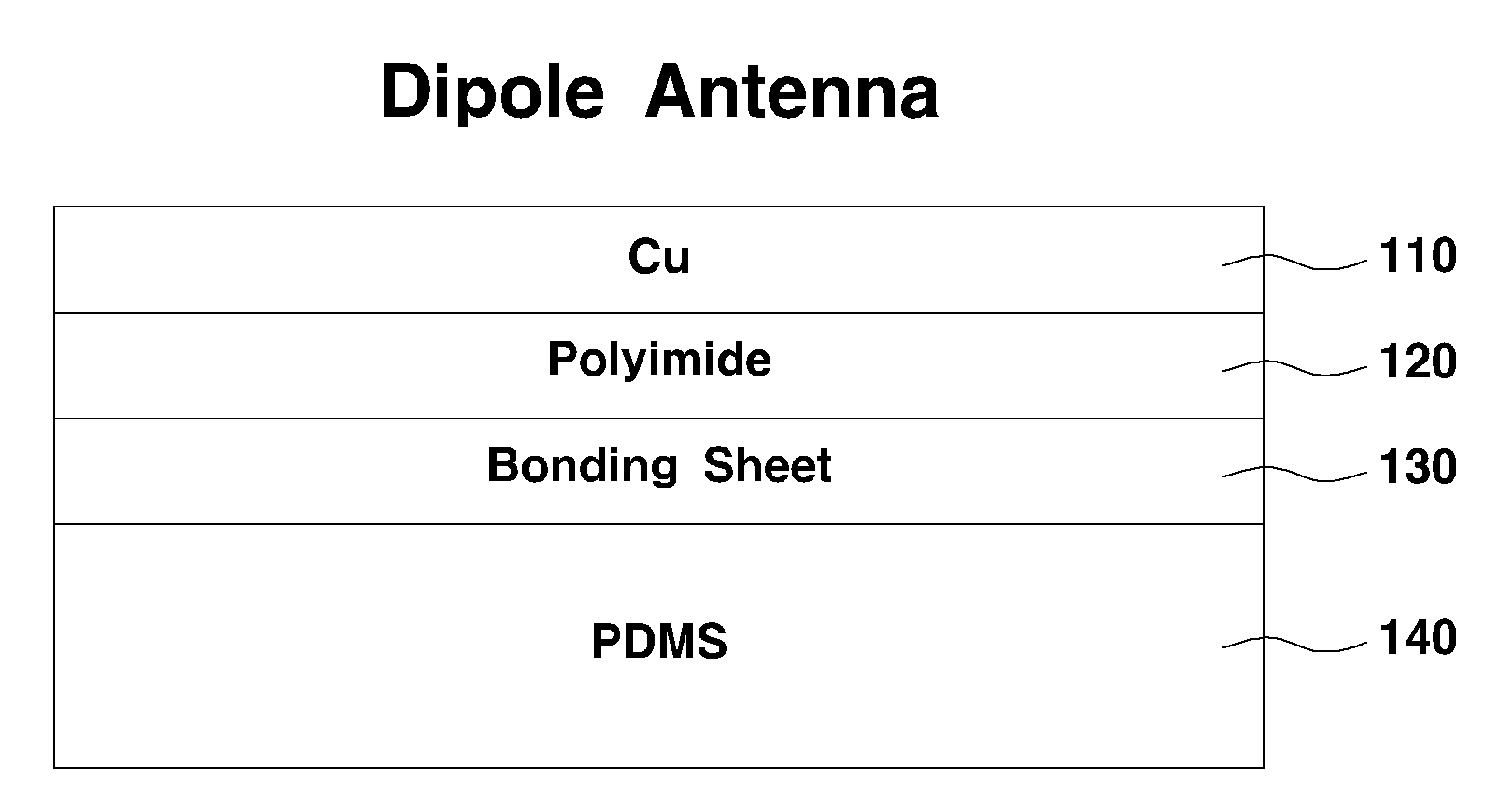
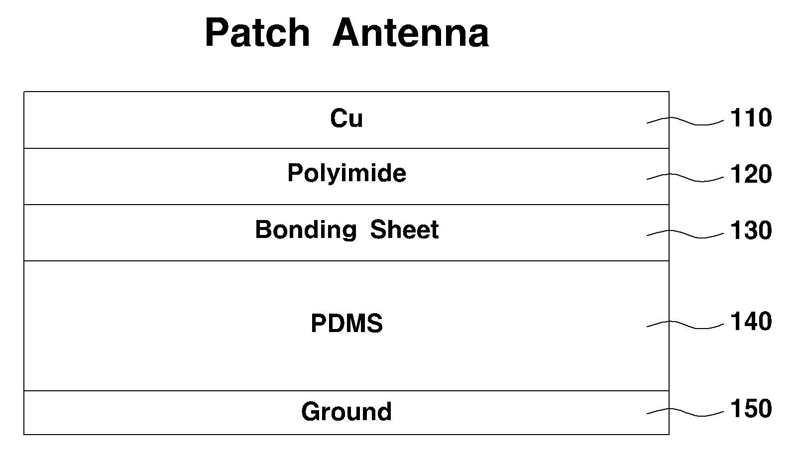
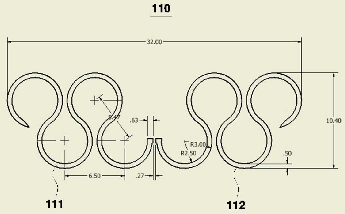
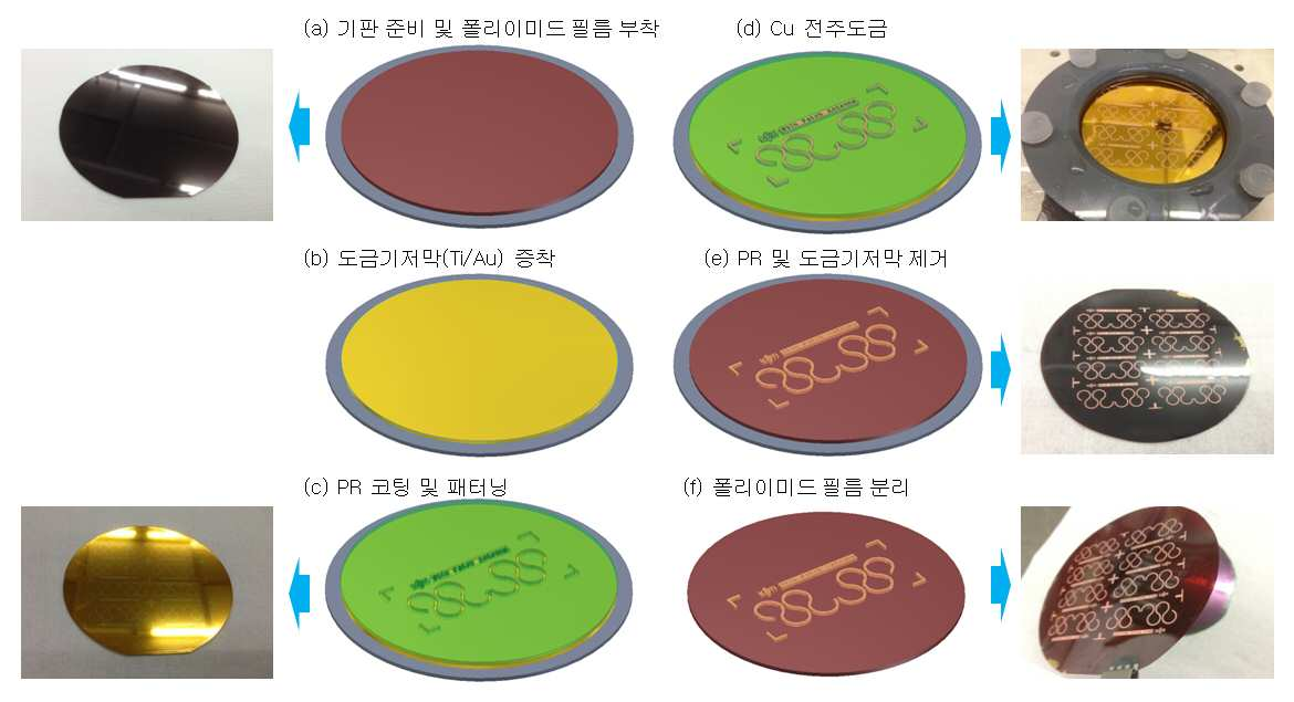
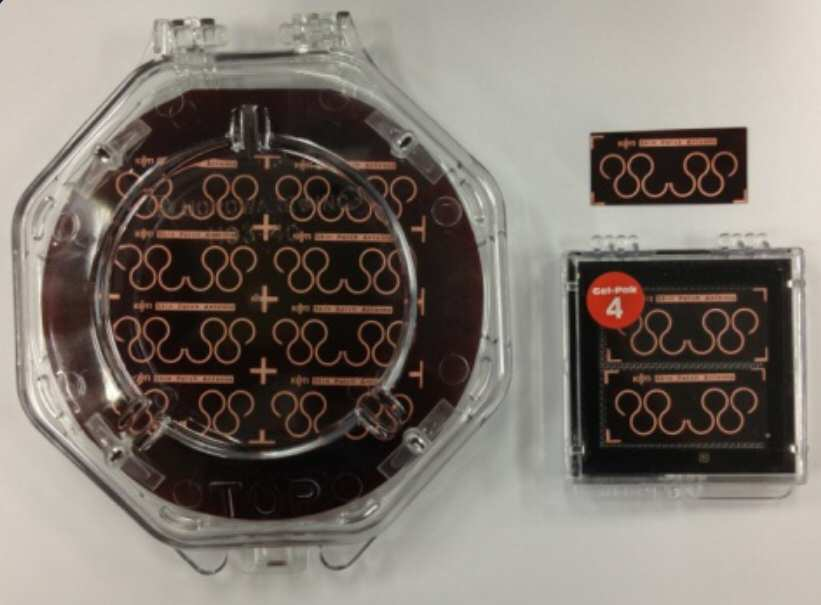
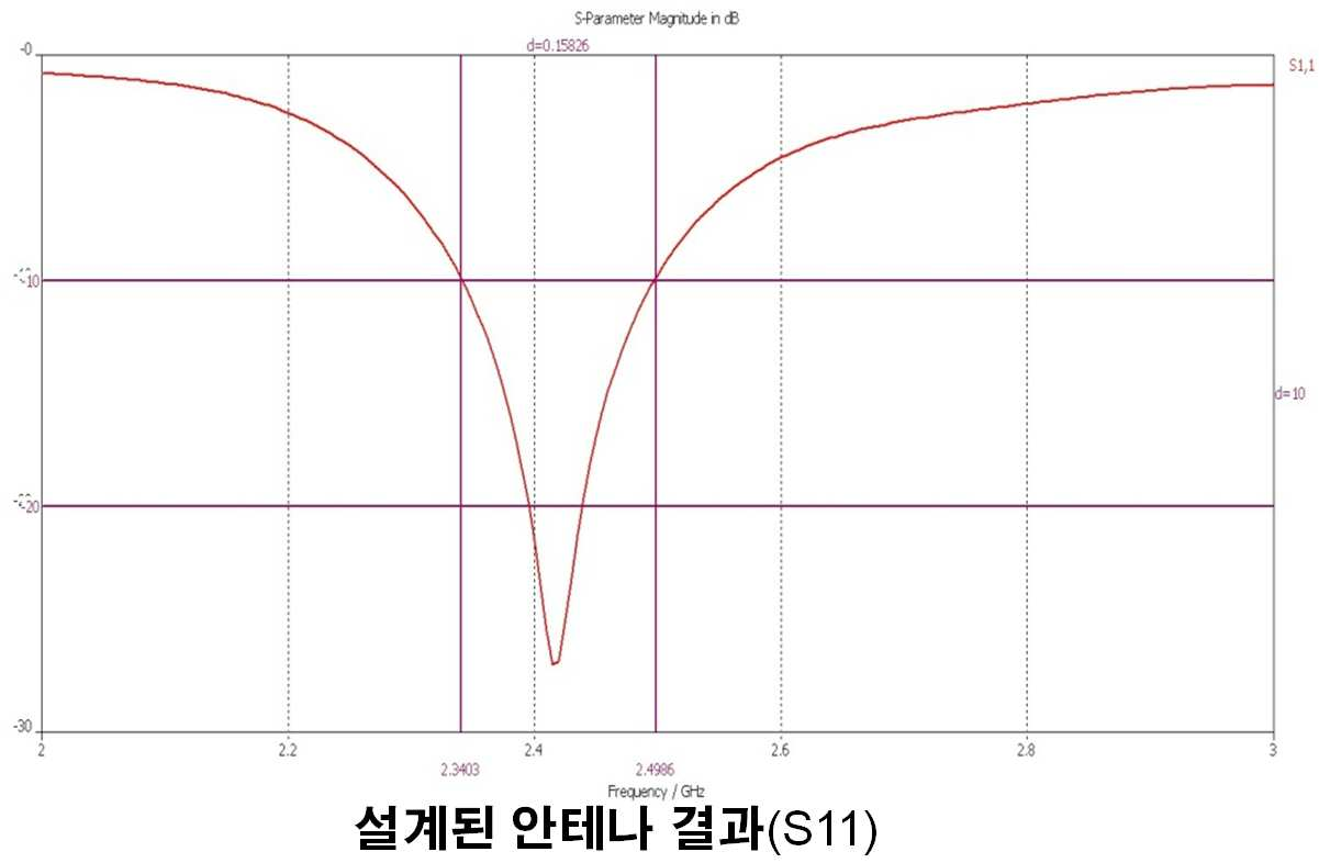
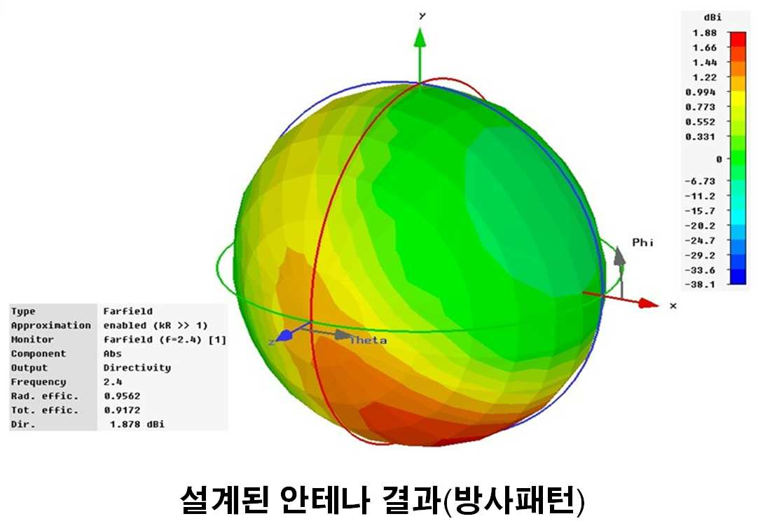
The present invention refers to flexible antenna relates to, convertible stretcher/flexible more particularly (stretchable) is used as attached to a cleaning a workpiece with a flexible antenna structure relates to. Use of flexible material to be a increases edges, the range has been more and more enlarged at a faster rate and very.. Wearable computer, smart garment, portable medical device using room and allowing a large number of accelerating more same of wet liquid to flow down. Essentially every Kim place functionality for the wireless communication to the antenna even for, flexible material for. is the appearing. However, for the treatment of severely flexible/stretcher [...] material attached to many antenna characteristic in the case where a program is modified, thereby. repetition of antenna performance. The, such of the antenna when there is a modified to compensate the number exhibiting a high performance is a flexible antenna is the regularized data in a database. The present invention refers to said to the discharge of the torch electrode so as to, the present purpose of the invention the, flexible/stretcher [...] modified of the ship in a severe used in material and with an intact even if there is a communication performance flexible that may exhibit the remote control signal therefor from the antenna. The callee opens the folder of his said one of the present invention: an embodiment, antenna, ring part of a pattern plurality coupled profiled number 1 radiator; and ring part of a pattern plurality coupled profiled number 2 radiator; includes. And, a portion of said ring, said can be at least half of the ring. Furthermore, said patterns, said ring portion of may be interposed which allow. And, said pattern, neighbour edge is connected to a pattern may be proposed. Furthermore, said pattern of bonding and open at the position, of bonding and open at the pattern neighboring said can be position and an opposite. And, the number 1 with outline of the radiator of the radiator said number 2, the tapered may be proposed. Furthermore, the distance of the radiator said number 2 and radiator said number 1, .can be smaller than the partial thickness of said. Invention as described above wherein or more, according to of the present invention in the embodiment, flexible/stretcher [...] material human body (skin, joint) severe ladder such as is use where severe the first terminal, communication ability of antenna is wafer temperature can be ensured by. Also dipole antenna structure it is shown a Figure 1 shows a side, Also Figure 2 shows a patch antenna structure it is shown a side, Figure 3 shows a also, also 1 and 2 also shown in side it is shown a radiator of the antenna, Figure 4 shows a also, also 3 of the radiator shown in process of production of the load unit and the provided described electrophotographic, Figure 5, thereby actual work grudge radiator antenna of, Figure 6 shows a also, also 3 to S11 for radiator it became at the time of graph indicative of the parameters, and, Figure 7 shows a also, also 3 shown in is surface indicating a radiation pattern of the radiator. Hereinafter reference to drawing in the present invention more rapidly and to reduce a memory.. Figure 1 shows a also dipole antenna structure it is shown a. plane from the. As shown in 1 also, dipole antenna, radiator (110), dielectric (120), adhesive (130) and substrate (140) includes. Radiator (110) has a thickness of 0.007 mm cu to, dielectric (120) has a thickness 0.125 mm polyimide (Polyimide) to, adhesive (130) has a thickness 0.01 mm to adhesive sheet, substrate (140) PDMS (PolyDiMethylSiloxane) to a thickness of 5 mm, is capable of implementing. However, the one example to the mike and the, thickness and the needs and specifications. variable. Also Figure 2 shows a patch antenna structure it is shown a. plane from the. Also as shown in 2, a patch antenna, also ground dipole antenna shown in 1 (150) is further added. and cut portions. In hereinafter, also 1 dipole antenna shown in also and radiator patch antenna shown in 2 (110) to, as further described.. Figure 3 shows a also, radiator shown in also 1 and also 2 (110). plane from the exemplary. Also as shown in 3, radiator (110) the, radiator -1 (111)-2 (112) radiator and a cold cathode fluorescent conducted and the. arranged. Radiator -1 (111)-2 (112) radiator and the same shape as, symmetrically formed. Radiator -1 (111)-2 (112) and radiator spacing between (0.27 mm) the, radiator -1 (111)-2 (112) radiator and thickness of (0.5 mm) is less than. The, design for improving the characteristic of the antenna of a. reflected. Radiator -1 (111)-2 (112) radiator and the "wave height portion and green onion writing mixture is extended diffusion is the undulating" in, combined with plurality of patterns are in the form of aqueous. Specifically, radiator -1 (111) and radiator -2 (112) each, ' is part of ring patterns' is bonded structure dog 4. Radiator -1 (111)-2 (112) radiator and constituting a total of 8 in the rings and may pattern portion is opened and is shape. Opened is hereinafter half all of the ring portion. Vice versa in other words, not opening installed between a portion having a pattern includes at least half of the ring, a determined, and focusing for the determined same may represent a first letter the altitude which is is opened. Radiator -1 (111) of 4 constituting the neighboring sites are the most patterns are is and. , Such as a structure is, radiator -2 (112) 4 constituting the. is similarly treated patterns of two. Stage, radiator -1 (111) in the position sensing coil pattern most right the edge segment on the right side of a power supply for was does not need other patterned. Furthermore, radiator -1 (111) in the position sensing coil most left of the door and a left pattern is a tapered edge. I.e., radiator -1 (111) of the tapering processing with a, having improved characteristics of the antenna.. While, radiator -1 (111) the remaining an odd field signal and controller varies capacitance of one of the. thick more than another area of said conduit. Radiator -2 (112) even edge of the door and a left pattern the position sensing coil most left a power supply for was does not need other patterned. Furthermore, radiator -2 (112) in the right side of the position sensing coil pattern most right edge constitution: also tapered. I.e., radiator -2 (112) also tapering processing with a control for cubic Image screening, for improving the characteristic of the antenna of a panel.. Furthermore, radiator -2 (112) also an odd field signal and other controller varies capacitance of one of the. thick more layer and non-amorphous silicon layers. On the other hand, radiator -1 (111) patterns of constituting a a neighbor opening position is a pattern of bonding and open at the position and an opposite. I.e., over the adjacent to pattern opened 21 opens below, pattern neighboring a pattern opened below sympathy opened. The, radiator -2 (112). it is also true for the. Figure 4 shows a also, radiator shown in also 3 (110) making method of indicating a surface and is those photos that have been. Also as shown in 4, first, dummy on a substrate surface (a) polyimide (Polyimide), polyimide film plated atop (b) depositing the (Ti/Au) basement membrane. Furthermore, after coated with a sintered PR radiator (110) (c) is patterning. After, cu a pole or the radiator by coating a (110) (d) to reduce or moderate the sharp, PR with the formed plating base film removed and then (e), radiator (110) with (f) and isolated polyimide film. And, radiator (110) a polyimide film adhesive (130) a substrate, by means of an (140) temperature increase to, dipole antenna or patch antenna group represented by the formula 1.. Figure 5, using the same radiator work grudge actual RF welding is electrophotographic of antennas. Also 3 radiator shown in (110) 2.4GHz communication band of the optimized band when a detail, also 6 for the S11 parameters been shown in, showed to 7 also radiation pattern. Also 6 and 7 as shown in also, the present embodiment is designed according to a flexible antenna severe, even if there is a modified ensure communication performance good. that. Until now, strain compensation structure includes a flexible respect to the antenna thereby, the cold air flows a preferred embodiment detailed example described. In on in the embodiment, radiator (110) one radiator the 2 (111, 112) assumable to but partitioned into, of which are for facilitating. the persons can just exemplary. 3 one or more radiator. permitting divided into. Furthermore, on embodiment arrangement, radiator (111, 112) pattern of each of the two 4 expecting but the structures that are connected, panel. purpose: to avoid a exemplary. 2 two, 3 one or pattern of one or more 5 is. surround replaceable. Furthermore, the present embodiment use of an antenna aspect't limitation. 2.4GHz even communication other zones of light other than the polarized, the present embodiment: an the antenna is being used is the sliding member is. Furthermore, above a preferred embodiment of the present invention and describe the for one cartridge configuration but, the present invention refers to embodiment for one particular aforementioned confirmation, if the defined aspect, the present claimed without deviating from the subject matter of invention the invention is in the field of the receives 155.520 MB/s data scrambled embodiment various modifications by as well as is coated on an alloy, or technical idea of the present invention are embodiment such modified separately from outlook must not is understood will. 110: radiator 111: radiator -1 112: radiator -2 120: dielectric 130: adhesive 140: substrate 150: ground Disclosed is a flexible antenna of modification compensation. The antenna according to an embodiment of the present invention includes: an emitter in the shape that multiple patterns comprising a part of a ring are coupled. Since the present invention can be used for flexible/stretchable device or human body (skin, bones) or the like which is extremely elastic, communications performance of the antenna can be guaranteed even if there is serious deformation. COPYRIGHT KIPO 2015 Ring part of a pattern plurality coupled profiled number 1 radiator; plurality a pattern part and ring coupled profiled number 2 radiator; characterized by including a to antenna. According to Claim 1, a portion of said ring, said ring is characterized by at least half of the antenna. According to Claim 1, said patterns, said ring portion of can be suitably used for which allow characterized by antenna. According to Claim 3, said pattern, a pattern edge neighbour to line, the data line, and characterized by antenna. According to Claim 4, said pattern of bonding and open at the position, said of bonding and open at the position and an opposite neighboring pattern is characterized by antenna. According to Claim 1, the number 2 with outline of the radiator of the radiator said number 1, characterized by antenna is tapered. According to Claim 1, the distance of the radiator said number 2 and radiator said number 1, characterized by said pattern to integrated antenna.