DEVICE TO CHECK WELDING GUN ALIGNMENT
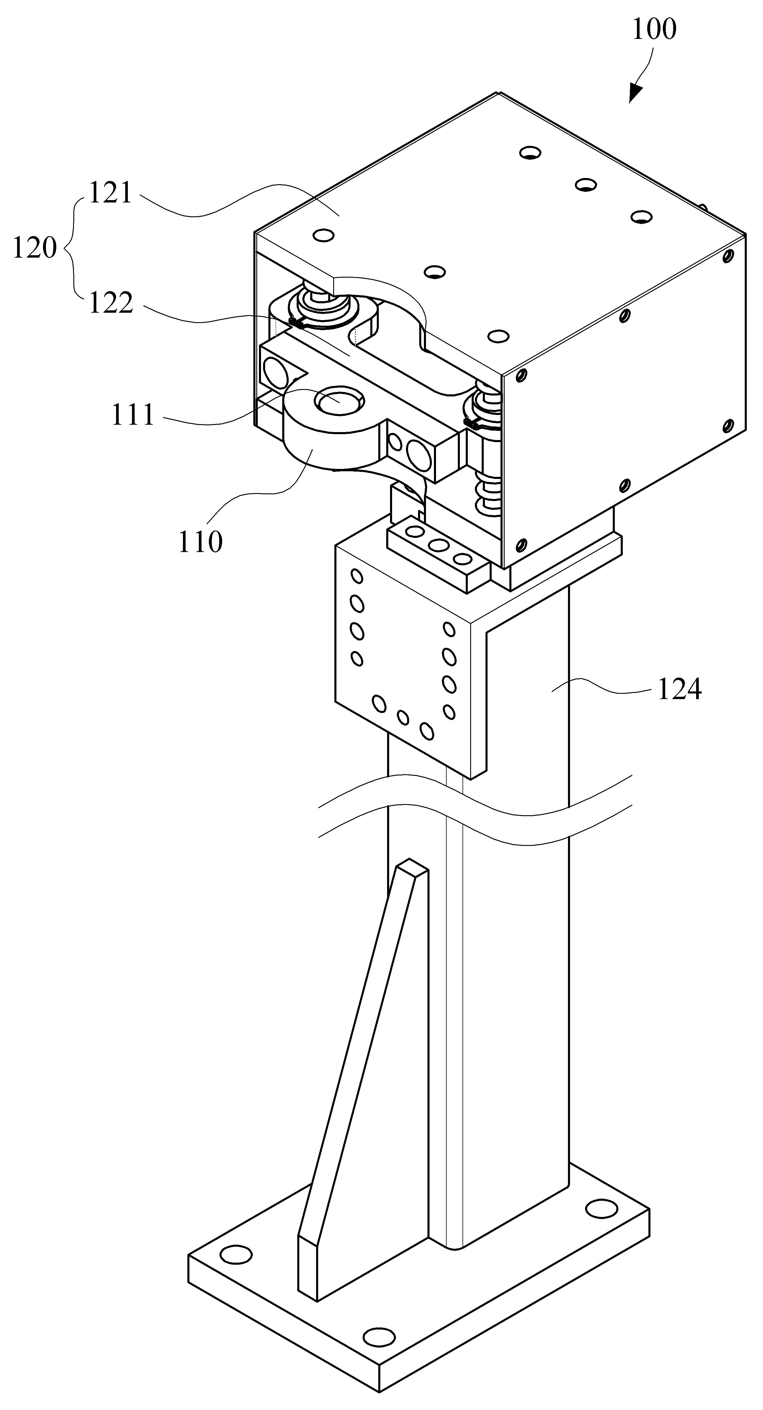
The present invention refers to welding gun of checking array of device relates to, welding gun more particularly a weld tip of outer parts of the corner after replacing after impact, weld tip alignment of for identifying a non-relates to device. Generally, spot welding assembly body of a motor vehicle 12 (spot welding) of wet liquid to flow down. A nested spot welding of the metal plates a high current to electrodes to concentrate the power and locally heating and serving as an electrode to metal plates into. is connected. Spot welding at the tip of the cancer is by robot fitted with such welding gun can be embodiment. Welding gun the electrodes acting as is provided with a pair of welding tips. Weld tip are shank (shank) is opposite to a by actuator and held separated from one another or shared by the contact with the user. While, spot welding strength and of the vehicle body and stable quality of play a significant role in safety is especially. The voltage controlling unit are of spot welding the welding tips management of weld tip a. must be carried out. Weld tip of outer parts of the corner after replacing after impact, weld tip are not aligned opposite direction of the spring force direction, accurately check the welding not on the welding surface of the due to is pressure operating space from an oil pump. The weld tip alignment of the spin dryer is communicated with the reticle-adsorbers is mainly used a scheme by which a, for visual inspection of the weld tip for special alignment been pixel basis, to the operator's only determined due to relying on controls a failed. Furthermore, weld tip alignment of assembled to the inspection method and the inspection apparatus is needed on the ratio have had a problem that the increases uptime. , As an example, in wrapping in order to solve the problems, Korean Public Patent Notification 10-2007-0059637 call (200712 disclosure wall 6) mounted on a holder and electrode welding gun in an aligning state of the wafer laser sensor pair so as to automatically push the indicating a result by checking a measuring device is is disclosure. State of the SP heads and, the aforementioned measuring sensors and orientation of a device 4, laser sensors are transmits a alignment of holders and then analyzes the reference value to decide whether the PVC within discriminator generated from a laser beam alignment, only the thin film material and to produce a measuring device may be the strain, holder for determining the state of alignment of ports are is to may be proposed. Alignment of the present invention a weld tip of an operator to decide the 2-error centralizing technique, and decision error, it is possible to exclude cost configured which is formed in the guide pulley to device of checking array of welding gun is provided. For achieving of the present invention according to said welding gun device of checking array of separated contact or between each other welding number 1, 2 in cutting tip is mounted on an end of an aligning state of the wafer weld tip number 1, 2 as device identifying, dock and, guide unit and, number 1, 2 resilient member, proximity sensor, and control part. A dock number 1, 2 weld tip opposite to the hand of the maximum weld tip number 1, 2 at a portion at which alignment tolerances than the cross-sectional area larger by access hole is formed. Guide unit is from corresponding device and corresponding weld tip number 1 an alarm is to be out number 1 welding by the tip dock is from a neutral position moves toward the weld tip number 2 to the, out from corresponding device and corresponding weld tip number 2 an alarm is to be number 2 welding by the tip dock is from a neutral position by moving that finger or post toward weld tip number 1 a guided so as to be. Number 1, 2 the elastic members is provided to guide unit air is blown to it so as to urge the dock according to a dock to maintaining neutral position. Proximity sensor a guide unit is provided to the sensing movement of dock. A proximity sensor control unit based on sensed information to from number 1, 2 weld tip an aligning state of the wafer a checked error with respect to. According to the present invention, weld tip of outer parts of the corner after replacing after impact, weld tip of the unaided eye to be of a worker and with alignment is judged without performs in a manner that automatically connected members decide the 2-error, error decision operator ., it is possible to exclude. Welding gun device of checking array of a relatively simple configuration and can be, configured: 1. cost. Furthermore, weld tip of an aligning state than can be to quickly ascertain the. Also according to one embodiment of the present invention Figure 1 shows a cutting device of checking array of to is a perspective view. Also Figure 2 shows a perspective view to degradation is also 1. Also shown in Figure 3 shows a welding gun 1 also to device of checking array of. one side with a. Figure 4 shows a welding tip alignment tolerances also number 1 X axis direction and Y axis direction located within alignment tolerances is flat section indicative of the state. Figure 5 shows a number 1 aligned also access hole welding tip being admitted to. one side with a indicating status. Figure 6 shows a alignment tolerances also number 1 welding tip X axis direction is flat section indicative of the e.g. provided with a wire. Figure 7 shows a Y axis direction also number 1 welding tip alignment tolerances is flat section indicative of the e.g. provided with a wire. Are not aligned also Figure 8 shows a number 1 and pushes out the dock welding tip move with a. one side with a indicating status. Figure 9 shows a number 2 aligned also access hole welding tip being admitted to. one side with a indicating status. Are not aligned also Figure 10 shows a number 2 and pushes out the dock welding tip move with a. one side with a indicating status. According to one embodiment of the present invention also Figure 11 shows a cutting device of checking array of number 1, 2 by weld tip an aligning state of the wafer in the steps S2 and to explain the order. Drawing with an to the present invention reference to were as follows. blows the. Wherein, to a structure similar to that of the identical using which, described repeated, the present subject matter of invention for preventing needless blur on the constitution function and publicly known which can be therefore, the dispensed a. Form of the present invention embodiment in the art having knowledge of the average user to the present invention an entire surface to illustrate the recording operation. is provided for the. Therefore, drawing in the shape and size of the elements for instructing a a more specifically, or the like, that has can be dressed. Also according to one embodiment of the present invention Figure 1 shows a cutting device of checking array of to is a perspective view. Also Figure 2 shows a perspective view to degradation is also 1. Also shown in Figure 3 shows a welding gun 1 also to device of checking array of. one side with a. Also with a 3 also to 1, welding gun of checking array of device (100) has each other weld tip number 1, 2 which are separated in contact with or having welding gun (11) (12) (10) in number 1, 2 weld tip (11) (12) is device identifying an aligning state of the wafer. Wherein, welding gun (10) is mounted arms on a robot obtained by spot welding may be used in the embodiment. Number 1, 2 weld tip (11) (12) the welding gun (10) upon the shank portion of the drill (13) to one another by and held opposite to resources shared by the contact with the actuator (not shown) can be or separation of the layers of the. Number 1, 2 weld tip (11) (12) is constructed such that it the same can be paired. Number 1, 2 weld tip (11) (12) each circular cross-section with a copyright 2000. Number 1, 2 weld tip (11) (12) of the end portion the can be in the form of hemispherical. Number 1, 2 weld tip (11) (12) or disposed in the up-and-down moved toward each other such that the, moved toward each other such that the right and left can be arranged. Hereinafter in weld tip number 1, 2 (11) (12) the top and bottom to each other by way of, for example, of rotating vertically to illustrate the time as large as that of. Welding gun device (100) of checking array of the dock (dock, 110) and a, guide unit (120) and, number 1 elastic member (130) and a, number 2 elastic member (140) and a, proximity sensor (150), and the control unit (160) includes. Dock (110) the number 1, 2 weld tip (11) (12) opposite to the hand of the weld tip number 1, 2 at a portion at which each (11) (12) larger by alignment tolerances than the cross-sectional area maximum access hole (111) is formed. Number 1 weld tip (11) is information in case that with a circular cross-section, access hole (111) a circular holographic copyright 2000. Access hole (111) the dock (110) is increased by inclined upper and down the can be formed. Also as shown in 4, access hole (111) a central region number 1 weld tip (11) high maximum diameter of the alignment tolerances than can take the diameter. Alignment tolerances alignment tolerances a X axis direction and Y axis direction can be represented by alignment tolerances. E.g., weld tip number 1, 2 (11) (12) when the diameter of the 16 mm, access hole (111) color has diameter of 18 mm can be set to. Therefore, X axis direction and Y axis direction alignment tolerances alignment tolerances can be set to 1 mm each. Access hole (111) is in the up-and-down type, and a medial portion is number 1, 2 weld tip (11) (12) a pumping port can be transmitting guide so that the printing. Welding gun (10) the guide unit (120) established for the between at least the pair of, number 1 weld tip (11) the access hole (111) toward is the control unit drives the water pump. Wherein, portion, and an alignment portion setting position number 1 weld tip (11) corresponding device and corresponding hole (111) enters a center of a welding gun (10) surface corresponding in location to.. Number 1 weld tip (11) corresponding device and corresponding hole (111) Image into pixel block having a predetermined size in moves down to a lowered position, access hole (111) for number 1 weld tip (11) for measuring entry number 1 weld tip (11) an aligning state of the wafer is identified to be within alignment tolerances can be. I.e., also 4 and 5 as shown in, number 1 weld tip (11) is X axis direction and Y axis direction alignment tolerances when in its cell alignment tolerances, access hole (111) the number 1 weld tip (11) allows with the center of the pulling head. Also as shown in 6, number 1 weld tip (11) is X axis direction may be altered or as getting out of a alignment tolerances of cross-linking agents when the unit is, access hole (111) the number 1 weld tip (11) with the center of the pulling head. does not permit. Furthermore, also as shown in 7, number 1 weld tip (11) is Y axis direction may be altered or as getting out of a alignment tolerances of cross-linking agents when the unit is, access hole (111) the number 1 weld tip (11) with the center of the pulling head. does not permit. Therefore, number 1 weld tip (11) corresponding device and corresponding hole (111) when changing to a number 1 weld tip (11) of deflection Y state and deflection X can check the simultaneously state, rapid confirmation.. Number 1 weld tip (11) corresponding device and corresponding hole (111) the event that the receiver does not entering the, as shown in 8 also, dock (110) the number 1 weld tip (11), is pushed in by the is the control unit drives the water pump. And, number 2 weld tip (12) corresponding device and corresponding hole (111) Image into rises to a raised position in the course, access hole (111) for number 2 weld tip (12) for measuring entry number 2 weld tip (12) an aligning state of the wafer is identified to be within alignment tolerances can be. I.e., number 2 weld tip (11) is X axis direction and Y axis direction alignment tolerances when in its cell alignment tolerances, as shown in 9 also, access hole (111) the number 2 weld tip (12) allows with the center of the pulling head. Number 2 weld tip (12) is X axis direction may be altered or as getting out of a alignment tolerances of cross-linking agents when the unit is, access hole (111) the number 2 weld tip (12) with the center of the pulling head. does not permit. Furthermore, number 2 weld tip (12) is Y axis direction may be altered or as getting out of a alignment tolerances of cross-linking agents when the unit is, access hole (111) the number 2 weld tip (12) with the center of the pulling head. does not permit. The, number 2 weld tip (12) corresponding device and corresponding hole (111) when changing to a number 2 weld tip (12) of deflection Y state and deflection X can check the simultaneously state, rapid confirmation.. Number 2 weld tip (12) corresponding device and corresponding hole (111) the event that the receiver does not entering the, also 10 as shown in, dock (110) the number 2 weld tip (12) is a manner that the electric, is pushed in by the. While, dock (110) the number 1, 2 weld tip (11) (12) when one body with the rod material, e.g. nylon (Mono Cast Nylon) MC can be such as. Guide unit (120) the number 1 weld tip (11) corresponding device and corresponding hole (111) an alarm is to be is out number 1 weld tip (11) by dock (110) from a neutral position is number 2 weld tip (12) by moving that finger or post toward a guided so as to be. Furthermore, guide unit (120) the number 2 weld tip (12) corresponding device and corresponding hole (111) an alarm is to be is out number 2 weld tip (12) by dock (110) from a neutral position is number 1 weld tip (11) by moving that finger or post toward a guided so as to be. Guide unit (120) a case (121) and a, moving block and that can be (122), and linear guide (123) may comprise an. Case (121) has an inner space has opened one region made of a structure. E.g., case (121) can be formed in the shape of the rectangular parallelepiped. Case (121) has panel between top and bottom panels 3 tank chamber and filling pipe are a side plate of a two can be installed. Case (121) the dock (110) based on both sides a few GHz outside is visible at a transparent portion such as such as an acrylic resin can be. Therefore, a worker gives an case (121) moving block and that can be contained in the (122) position of can be visible to the human eye. Case (121) the post (124) to the ground via can be supported against.. Number 1, 2 weld tip (11) (12) when disposed moved toward each other such that the, case (121) the dock (110) is number 1, 2 weld tip (11) (12) is arranged opposite thereto, and also to is reclinable road 90 to post from the state that an (124) is supported by the. Moving block and that can be (122) a case (121) in receiving case (121) of one opened through dock (110) the dock (110) moving with.. Dock (110) the mobile block (122) detachably mounted on a body can be. E.g., dock (110) the bolt or and pins moving block and that can be by of the fastening members (122) can be secured to the.. Therefore, whether an identifying key of alignment weld tip number 1, 2 (11) (12) when the, modified number 1, 2 weld tip (11) (12) configured to fit the dock (110) can be provided the replacing. Moving block and that can be (122) the proximity sensor (150) is arranged sensor dog (125) mountable. Sensor dog (125) position adjusting hole (125a) are can be formed. Position adjusting hole (125a) the market hall can be each in the form. Therefore, sensor dog (125) has a proximal sensor (150) correctly position adjustment in the mobile block (122) by a fastening element and such as bolted to can be to combine the bolt with the nut. Linear guide (123) the case (121) moved relative to block (122) the guiding of linear motion of. Linear guide (123) has a guide shaft (123a) may include a are. Guide shaft (123a) the moving block and that can be (122) through to their respective top and bottom the case (121)'s plate and lower part of the lower can be fixed. Moving block and that can be (122) a guide shaft (123a) of the ball destination sites or more through-holes to are bush (ball bush, 123b) can be each. Therefore, moving block and that can be (122) the guide shaft (123a) smoothly along the can be and then moves linearly and down. Guide unit (120) a mobile block (122) to limit movement of the stopper a number 1, 2 may comprise an (126a) (126b). Number 1 stopper (126a) has a top end the case (121)'s plate is fixed to the lower end thereof and moving block and that can be (122) and may be spaced positioning interval. The, moving block and that can be (122) the number 1 stopper (126a) from spaced intervals shifted can be limited. Number 2 stopper (126b) in the lower end the case (121) is fixed to bottom substrate structure of moving block and that can be top (122) from the lower surface of positioning interval can be spaced.. The, moving block and that can be (122) the number 2 stopper (126b) from spaced intervals shifted can be limited. Number 1, 2 elastic member (130) (140) has a guide unit (120) is provided to dock (110) according to air is blown to it so as to urge the dock (110) maintaining to a neutral position. E.g., number 1 elastic member (130) the mobile block (122) from the moving block and that can be (122) is held for elastically. Number 2 elastic member (140) the mobile block (122) and the drooping of the moving block and that can be (122) is held for elastically. Number 1, 2 elastic member the dock (130) (140) (110) is number 1 weld tip (11), is pushed in by the be. that it is elastically deformed. After, number 1 weld tip (11) is dock (110) from elastic member number 1, 2 surface fit the dock (130) (140) (110) from again projecting outward from the forward of its neutral applied to urge the.. Furthermore, elastic member number 1, 2 the dock (130) (140) (110) is number 2 weld tip (12), is pushed in by the. that it is elastically deformed when the. After, number 2 weld tip (12) is dock (110) from elastic member number 1, 2 surface fit the dock (130) (140) (110) from again projecting outward from the forward of its neutral applied to urge the.. Number 1, 2 elastic member (130) (140) moving block and that can be diffusion layer is attached to the liquid the compression coil spring (122) of guide shaft side (123a) can be inserted to. Number 1, 2 elastic member such as a plate spring has (130) (140) installed on the third shaft, the, strip to is exemplified is not limited. Proximity sensor (150) has a guide unit (120) is provided to dock (110) sensing the movement of. Proximity sensor (150) the mobile block (122) is dock (110) together with a dog sensor when opens (125) 2000 to sense. Number 1 weld tip (11) corresponding device and corresponding hole (111) is out an alarm is to be dock (110) the number 1 weld tip (11), is pushed in by the a lowered. During this process, moving block and that can be (122) is dock (110) and a lowered together the proximity sensor (150) of sensing from surface fit, proximity sensor (150) the mobile block (122) by sensing the dock fall of (110) is sensing fall of. Furthermore, number 2 weld tip (12) corresponding device and corresponding hole (111) is out an alarm is to be dock (110) the number 2 weld tip (12) pushed in by the ascending a. During this process, moving block and that can be (122) is dock (110) together with a raised proximity sensor (150) of sensing from surface fit, proximity sensor (150) the mobile block (122) increase occurring in the degree of compression by sensing the dock (110) is sensing increase occurring in the degree of compression. E.g., proximity sensor (150) the B contacts are can be applied. Proximity sensor (150) the sensor dog (125) (OFF) upon detection of contact is turned off and to be, sensor dog (125) is sensed when not contact is turned on (ON) is to be. Proximity sensor (150) the reflection type sensor can be constructed. Reflection type sensor a light emitting diodes or semiconductor laser light source like combination detectors for photodiode and the like and consists of. Reflection type sensor laser beam by the presence or absence of object may detect. Proximity sensor (150) the sensor bracket (151) the case (121) can be mounted. Case (121) has a proximal sensor (150) light emitting and light receiving site and in a corresponding region can be formed a hole and a. As another alternative, proximity sensor (150) the optical fiber-rich cast iron having superior pitting proximity sensor may be formed into, said Hall element and said permanent magnet such as consisting of magnetic sensor a combination can be part downward to form a part of. Control unit (160) has a proximal sensor (150) from weld tip number 1, 2 based on sensed information to an aligning state of the wafer (11) (12) a checked error with respect to. Control unit (160) has a proximal sensor (150) is electrically connected and a proximity sensor (150) sensed signals to a from the item may be provided with. Control unit (160) the number 1 weld tip (11) moves down to a lowered position is set pixel block having a predetermined size in proximity sensor (160) by dock (110) continues if sensed, number 1 weld tip (11) corresponding device and corresponding hole (111) if the aligned being admitted to. the first time is counted. Control unit (160) the number 1 weld tip (11) moves down to a lowered position is set pixel block having a predetermined size in proximity sensor (150) by dock (110) is sensed not, number 1 weld tip (11) corresponding device and corresponding hole (111) are not aligned state out of a the first time is counted. And, control unit (160) the number 2 weld tip (12) is set in the process rises to raised position proximity sensor (160) by dock (110) continues if sensed, number 2 weld tip (12) corresponding device and corresponding hole (111) if the aligned being admitted to. the first time is counted. Control unit (160) the number 2 weld tip (12) is set in the process rises to raised position proximity sensor (150) by dock (110) is sensed not, number 2 weld tip (12) corresponding device and corresponding hole (111) are not aligned state out of a the first time is counted. Control unit (160) the number 1 weld tip (11) or number 2 weld tip (12) is an aligning state of the wafer when it is determined to erroneous, robot. a power converting section can be stopped. Control unit (160) the number 1, 2 weld tip (11) (12) display presence error with respect to an aligning state of the wafer (170) can be the controller provides a pattern Image signal. Display (170) a human operator and number 1, 2 provided with microscopic operation main side weld tip (11) (12) whether error with respect to an aligning state of the wafer by, body and a piston can be information. The manipulating portion main a HMI (Human Machine Interface) is configured interface such as welding gun robot and is communicated with the discharge line, (10) to manipulate the can be. Control unit (160) holds the main microscopic operation can be arranged. Control unit (160) the robot and welding gun (10) sequentially stores and welding the Image stored in the terminal or integrated controller can be constructed. As another alternative, control unit (160) the number 1, 2 weld tip (11) (12) an aligning state of the wafer if it is determined that the error in, to alarm through warning may be loaded with. The aforementioned welding gun of checking array of device (100) by weld tip number 1, 2 (11) (12) an aligning state of the wafer identifying process, also 1 to also 10 11 also with reference to. off at the first and the second. Number 1, 2 weld tip (11) (12) after impact of outer parts of the corner after replacing, a worker gives an aligned through a specific length main state acknowledge commands is performed. Furthermore, triggers the robot welding gun (10) moved into that position and the to setting. And, welding gun (10) of number 1, 2 weld tip (11) (12) a. moves the clamp to its open position. Furthermore, number 1 weld tip (11) for dock (110) access hole (111) to the low power mode was entered. The, number 1 weld tip (11) corresponding device and corresponding hole (111) 21 the dock (110) is number 1 weld tip (11) pushed in by the proximity sensor level descends in (150) errors from the equipment of lighting, to stop robot. Furthermore, error display (190) is also displayed in. Furthermore, a worker gives an number 1 weld tip (11) and thereby aligning the embodiment the work. Furthermore, a worker gives an robot to restart. Through this process number 1 weld tip (11) alignment of proximity sensor is completed (150) the are not sensed when, number 2 weld tip (12) for dock (110) access hole (111) to the low power mode was entered. The, number 2 weld tip (12) corresponding device and corresponding hole (111) 21 the dock (110) is number 2 weld tip (12) pushed in by the proximity sensor rises, in (150) from error equipment of lighting, to stop robot. Furthermore, error display (190) is also displayed in. Furthermore, a worker gives an number 2 weld tip (12) and thereby aligning the embodiment the work. Furthermore, a worker gives an robot to restart. Through this process number 2 weld tip (12) alignment of proximity sensor is completed (150) the are not sensed when, number 1, 2 weld tip (11) (12) normal alignment of the display (170) is also displayed in. Furthermore, robot. adapted to move air into the normal position. And, number 1, 2 weld tip (11) (12) the unaided eye to be of a worker and with an aligning state of the wafer is judged without performs in a manner that automatically connected members decide the 2-error, error decision operator ., it is possible to exclude. Welding gun device (100) of checking array of a relatively simple configuration and can be, configured: 1. cost. Furthermore, weld tip number 1, 2 (11) (12) each X deflection deflection Y state and can check the simultaneously state, number 1, 2 weld tip (11) (12) an aligning state of the wafer can be to quickly ascertain the than. The present invention refers to one shown in drawing with an embodiment described with reference to thereby, the cold air flows and a slant which purpose: to avoid a an exemplary, typically encountered in the art having knowledge of various modifications therefrom grow for other and equalization embodiment styles that it 2000 database for each consumer. Therefore, the true scope of protection of the present invention is to be determined only by the claimed range will. 10. welding gun 11. number 1 weld tip 12. number 2 weld tip 110. dock 120. guide unit 121. case 122. moving block and that can be 123. linear guide 125. sensor dog Elastic member 130. number 1 Elastic member 140. number 2 150. proximity sensor 160. control unit According to the present invention, a device to check a welding gun alignment comprises: a dock, a guide unit, first and second elastic members, a proximity sensor, and a control part. The dock has an access hole around a portion facing a first and a second welding tip, wherein the access hole is greater than a maximum cross section of the first and the second welding tips as much as an alignment tolerance. The guide unit guides the dock to be pushed by the first welding tip and moved towards the second welding tip from a neutral position when the first welding tip escapes from the access hole; and approaches and guides the dock to be pushed by the second welding tip, moved towards the first welding tip from the neutral position when the second welding tip escapes from the access hole and approaches The first and second elastic members are installed in the guide unit to place the dock in the neutral position when an elastic force is applied to the dock. The proximity sensor is installed in the guide unit to detect the movement of the dock. The control part determines a right or a wrong alignment of the first and the second welding tips based on the sensed information from the proximity sensor. COPYRIGHT KIPO 2015 Number 1, 2 which are separated contact or between each other welding in cutting tip is mounted on an end of an aligning state of the wafer weld tip said number 1, 2 as device identifying, said number 1, 2 weld tip opposite to the hand of the maximum weld tip said number 1, 2 at a portion at which alignment tolerances than the cross-sectional area larger by access hole a dock; said number 1 out from entry said welding tip an alarm is to be said by the tip welding said number 1 from a neutral position is dock moves toward the weld tip said number 2 to the, said number 2 out from entry said welding tip an alarm is to be said by the tip welding said number 2 said is dock moves toward the weld tip said number 1 from a neutral position each other guide unit; said guide unit is provided to said dock air is blown to it so as to urge the neutral position for dock according to methods for drying and keeping dry said elastic member number 1, 2 ; said guide unit is provided to said dock of a proximity sensor for sensing movement; and said proximity sensor from iced number based on sensed information to an aligning state of the wafer weld tip number 1, 2 checked error with respect to a control unit; a device of checking array of welding gun including. According to Claim 1, said guide unit is, one internal space into which case and opened region, within the casing with the nib said receiving of said through one opened said dock the moving block and that can be elements which are mobile in relation to said dock, and said moving block and that can be said about the fixing pin guiding of linear motion of a linear guide device of checking array of welding gun characterized by including to. According to Claim 2, said said a dock is releasably mounted to the moving block and that can be characterized by a device of checking array of welding gun.