STAND TYPE LAUNDRY DRYING RACK
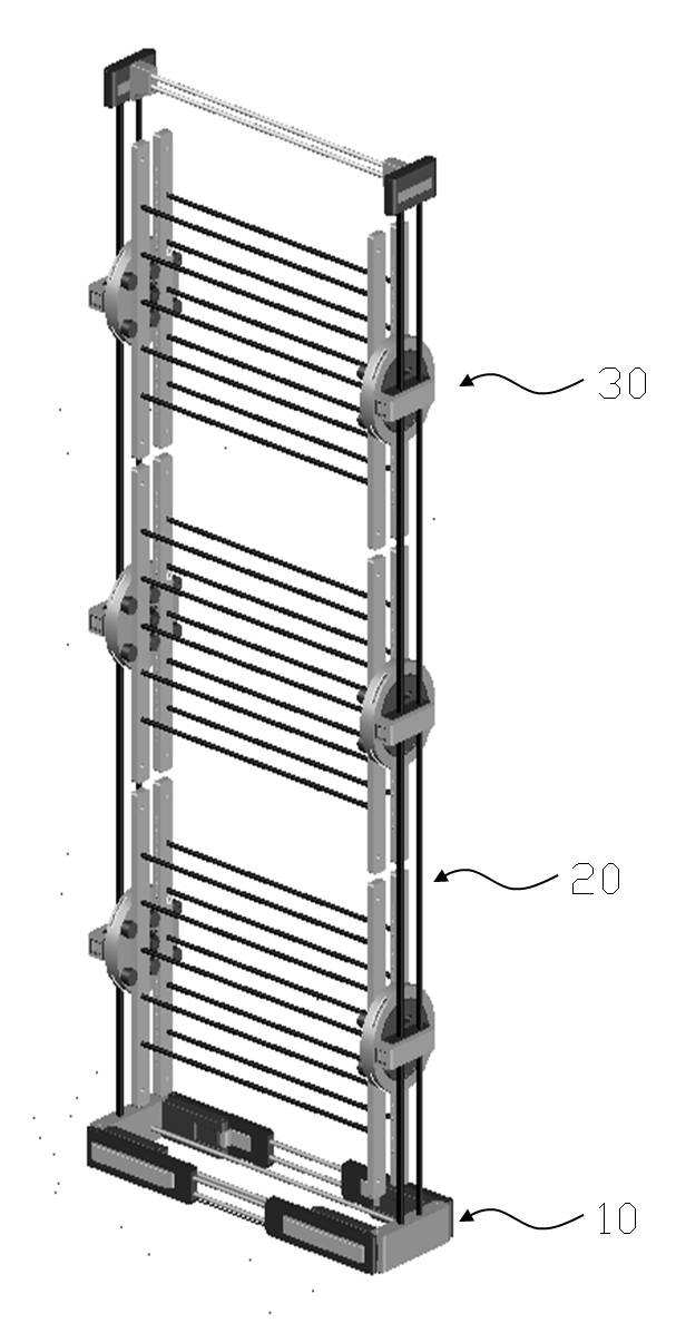
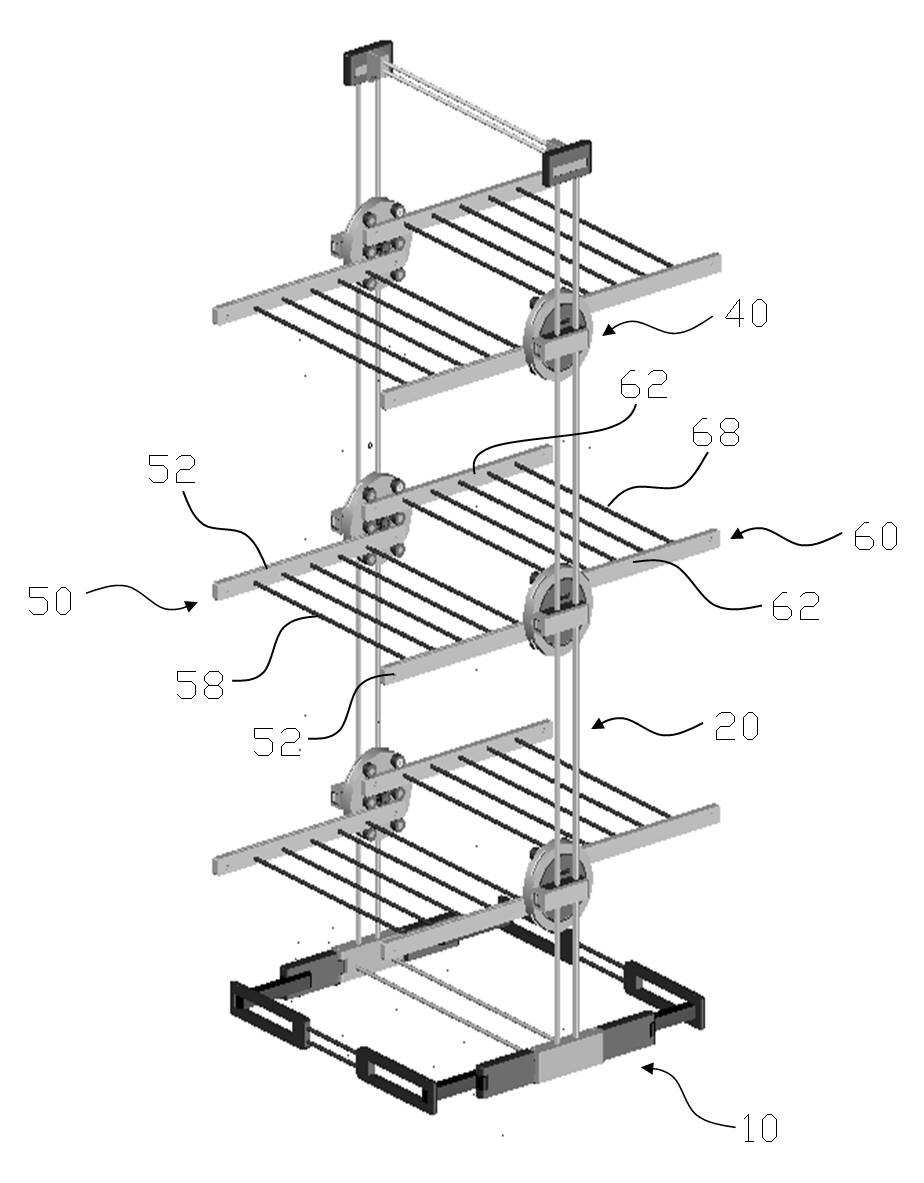
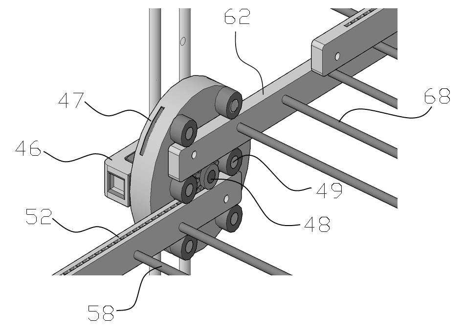
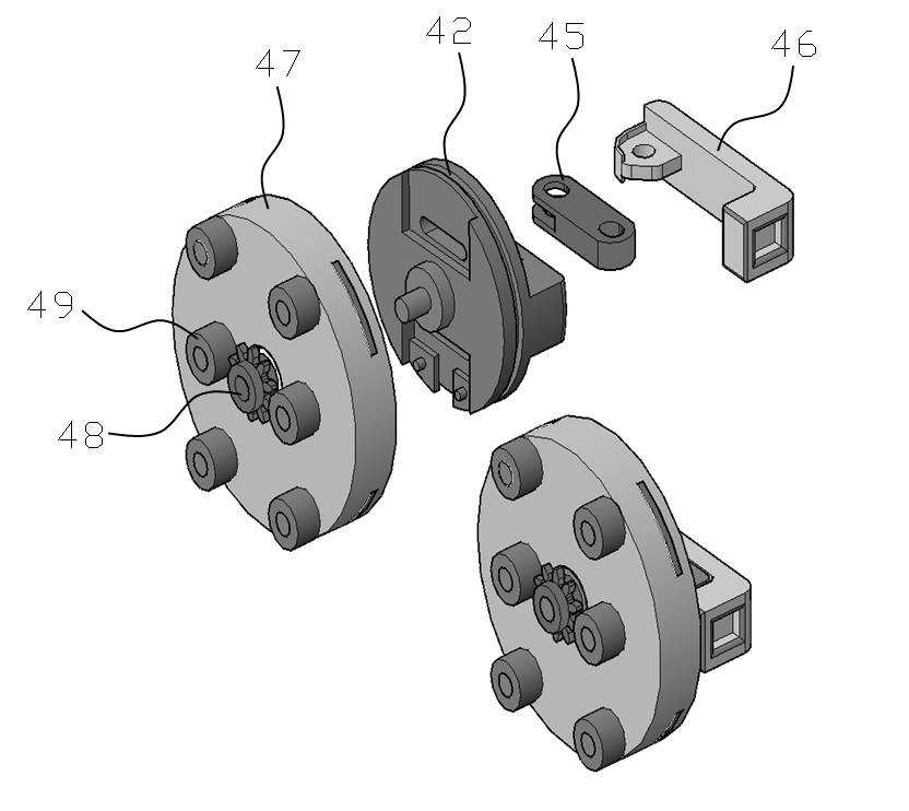
The present invention refers to laundry dryer relates to, and receives the object even not easily foldable stand type laundry closet official are disclosed. Current, used for drying the washing laundry washing in a household has been restored ceiling and installed and a connection to a type that scheme, space efficiency in both the turned on ball number foldable emphasized recently amount scheme are disclosed. In particular, a ground laundry can be restored storage and provided a user to select a position being greater in the database, the weight of the body to the other through so that the hereinafter for storage installation are disclosed. To prevent the insulating structure comprises a basic table symmetric shaft provided with a stand top hanger brackets adapted it becomes the paragraph concubine and the ground it stands tensely laundry hangable are disclosed. However, the structure is not strong when clear of the existing method to prevent long period, folding portion to prevent the coupling groove between door number point which, folded state back door number pad firmly state without the splayed or measured disclosed. In addition, self-contained and includes a radially lower stand not strong displayed various laundry such as the pin is readily detectable by the pad door number point. In addition, to prevent large amounts of drying the washing of the existing method at a place in the narrow to a plurality of hanger rod brake hanger for interval 9 consisting, in addition interval narrower winter cloth hanger and fourth ceramic is deposited as close to each other so that each connecting iron cotton clothes drying laundry comprising number without odor in door number point at the disclosed. In addition, the left side of the state of the existing method shows laundry hanged on a left brake hanger restored laundry because, by mesh door number point which generates the perception dibasic acids, metallic frame is coupled with the folding rate the perception door number even when the pin is the fine view point. In addition, the exposed as suffering from a radially or external contaminants to prevent laundry, laundry ground wind blows off contaminants attached to the pin is point number can fall out of the door. The present invention refers to prior art door number point such as described above in order to solve in a certain, tightly folded structure formed a laundry dryer stand that it does not break to improve durability and to which the pin is under public affairs number. In addition, the present invention refers to the hanged on a laundry in a laundry dryer or exhausting rate folding or easily members number under public affairs pin is used. In addition, the present invention refers to laundry and friction and preventing contact between the laundry can be dried efficiently to the pin is a laundry dryer or exhausting under public affairs number. In addition, the present invention refers to a door number mesh laundry hanged on a state or folding rate in improving a driving electrode and aesthetic feeling, laundry radially from contaminants or external pin is capable of protecting a laundry dryer or exhausting to under public affairs number. The present invention if the number to one or more pipeline and number and number are not, the present invention referred to herein as the selected number are not under the present invention is provided to another and may be in person with skill in the art to clearly understand from the substrate are disclosed. The present invention refers to stand type laundry dryer relates to, configuration is, lower end provided, standing supports a lower frame portion, said frame portion of the frame extends upwardly of a left-side lower end, said lower end of home bar frame portion provided at an upper side frame, said side pregabalin mouth bringing up for discussion rotating forward wire springs including a stand frame, said frame portion to prevent said elevating along lower side frame, said side frame portion extending forwardly about stand frame portion that are provided with a number 1, number 2 is provided as the stand frame portion extending rearwardly characterized. And, stand said frame portion, said lateral frames while moving along, rotatable and fixed part, said fixing part rotatable about a stand number 1 frame portion, said frame portion and rotatable about a fixing portion comprising a stand number 2, said number 1 stand frame portion extending opposite the number 2 stand frame portion characterized. Said fixing unit, said fixing body and moving along a side frame portion, said side frame portion selectively lock includes a fixed component and said fixed body, said fixed body rotatable in an up and down to the rotation bodies, said rotating body rotatably connected to the center of central gear, said frame portion of the frame about the central gear stand said number 1 at regular intervals spaced parallel both stand said number 2 is rotated by an amount is formed on the turning of the roller assembly is configured guide roller, said number 2 down central gear in engagement with said frame portion to prevent stand said number 1 frame portion from moving opposite to each other characterized. By number and is interposed in said, tightly folded structure formed to improve durability and to prevent breakage can be equal to or less than. In addition, washing laundry dryer stand of the present invention engaging the tape on the erected easily in rigid or folding rate can be equal to or less than. In addition, contact between the pivots and laundry washing laundry dryer stand of the present invention can be dried efficiently and equal to or less. In addition, washing laundry dryer stand of the present invention engaging the tape on the door or folding rate to improve mesh matrix is aesthetically pleasing and in number, equal to or less than protect radially from external contamination or laundry. Figure 1 shows a preferred embodiment the present invention also by the anti-to prevent general sensors mounted thereon. Figure 2 shows a in the embodiment operating state of the anti-perspective view of Figure 1. Figure 3 shows a in the embodiment other operating conditions the anti-perspective view of Figure 1. Figure 4 shows a configuration of a stand frame 1 also constituting also exhibit sensors mounted thereon. Figure 5 shows a configuration of a fixing part 1 also constituting also exhibit sensors mounted thereon. Figure 6 shows a 1 also constituting a process operation of the fixing portion also exhibit sensors mounted thereon. Hereinafter the present invention stand by a detailed preferred embodiment a closet laundry products on the attached drawing as follows. First, by the present invention as shown in the configuration of the laundry dryer stand also 1, lower end provided, standing supports a lower frame part (10) on, said lower frame part (10) of left and right side surfaces extending upwardly side frame part (20) and, said side frame portion (20) provided on top of the top of the home bar frame portion (28) on, said side frame portion (20) so that they can be forwardly of the stand comprises a number of frame portion (30) wherein, said drying frame portion (30) includes said side frame portion (20) wherein the elevating along, said side frame portion (20) extending forwardly about stand 999000098 8999 frame part (50) that are provided with a, stand frame portion extending rearwardly number 2 (60) can be provided. First, the present invention is to prevent lower frame portion by stand (10) is pair of substrates. Said lower frame part (10) is also 1 as shown, the present invention may be positioned vertically downward to stand in foam could be bonded each other. Said lower frame part (10) is the aforementioned purposes can be configured, in the present invention described conducted under frame portion (30) and can be of the same configuration. And, said lower frame part (10) of left and right side surfaces extending upwardly at one side frame part (20) is pair of substrates. Said side frame part (20) is, described below which the laundry to be hanging from a conducted to frame portion (30) located upwardly to could be bonded each other. Said side frame part (20) is also 1 as shown, said lower frame part (10) fixed to the both ends of each have a pair of bar upwardly in an can be. And, said side frame portion (20) upper end of the upper frame part (28) is pair of substrates. Said top frame portion (28) is also 1 as shown, said side frame part (20) is connected a vertically positioned [...] fractions of the week. Said side frame part (20) is drying frame portion (30) is pair of substrates. Said drying frame portion (30) has a predetermined curvature toward the laundry could be bonded each other. Said drying frame portion (30) includes said side frame portion (30) can be moved up or down along, with it is split into several pieces can be. Said drying frame portion (30) is aforementioned functions, said side frame portion (20) fixed and selectively moved along a fixing part (40) on, said fixed part (40) rotatable about the stand frame number 1 (50) on, said fixed part (40) rotatable about the stand number 2 frame part (60) consists of including. Said fixing part (40) horizontally extending hinge-coupled folded pant number 1 (50a) on, number 1 for discharging vertically extending vertical portion (50b) including number 1 a stand frame portion (50) on, said fixed part (40) horizontally extending hinge-coupled folded pant number 2 (60a) on, number 2 folded vertically extending vertical portion (60b) including number 2 a stand frame portion (60) can be connected to one end. First, stand said frame portion (30) is fixed part (40) is pair of substrates. Said fixing part (40) includes said side frame portion (20) selectively fixed to movement along could be bonded each other. Said fixing part (40) is, can be constructed as below. Said fixing unit, also as shown in 4 to 6 also, said side frame portion (20) while moving along said side frame portion selectively fixing body (42) on, said fixing body (42) rotatably connected to the rotating body in an (47) on, said rotating body (47) rotatably connected to the center of central gear (48) on, said central gear (48) stand frame portion about said number 1 (50) said number 2 on stand frame part (60) is rotated by an amount of turning of the roller is formed at regular intervals both spaced parallel guide roller (49) can be 999 0000258999 comprising Wherein, said number 1 drying frame portion (50) said number 2 on stand frame part (60) is said central gear (48) can be moved up and down in opposite directions and engaged. Said fixing body (42) is, as shown in fig. 6, said fixing body (42) side of the groove (42c) apparatus being, said groove (42c) the process number 1 through the vertical through hole (42d) and number 2 through hole (42e) and, said groove (42c) said number 1 is insertable into the through hole (42d) through hole and said number 2 (42e) corresponds to number 1 through the aperture (45a) and aperture number 2 (45b) formed fixing block (45) and, said number 2 apertures (45b) to [...] hingedly connected by a fixed lever (46) can be further provided. Said side frame portion (20) of number 1 bar (22) on number 2 bar (24) is said fixed part (40) so as to penetrate the consists of. Wherein, said number 1 through hole (42d) through hole and said number 2 (42e) is said number 1 bar (22) on said number 2 bar (24) diameter less than can be identically structured. And, said number 1 through holes (45a) and aperture said number 2 (45b) is said number 1 through hole (42d) and number 2 through hole (42e) size of can be different, can be elliptical configuration. This fixing lever (46) by fixing block of (45) to move said number 1 while through hole (42d) and number 2 through hole (42e) said number 1 and aperture (45a) and aperture number 2 (45b) by number 1 bar (22) on number 2 bar (24) when in a fixed are disclosed. More specifically described, said number 1 bar (22) is said number 1 through holes (45a) and number 1 through hole (42d) positioned so that the through, said number 2 bar (24) said number 2 is aperture (45b) and number 2 through hole (45e) positioned so passing through. The, said fixing lever (46) is rotated, hinged to a fixed block (45) while moving, said number 1 through hole (42d) number 1 and aperture (45a) while said number 1 to position the bar (22) sets a to be coated. Similarly, through hole said number 2 (42e) and aperture number 2 (45b) while said number 2 to position the bar (24) sets a to be coated. And, said fixed part (40) is rotating body (47) are disclosed. Said rotating body (47) the inner circular groove (47a) is formed, said groove (47a) to said fixing body (42) can be inserted circular's drive can be configured. Said rotating body (47) has said fixing body (42) while rotating along the outer circumference, the only 90 in one direction of rotation preferably. This, as shown in also 1 and 2 also, two sections can be moved when in a horizontal vertical one time andone time are disclosed. And, said rotating body (47) has a center gear (48) is pair of substrates. Said central gear (48) is also described under the stand frame number 1 (50) of frame number 1 (52) stand number 2 and frame part (60) of frame number 2 (62) to guide, toothed outer peripheral surface in the nanometer range. Said rotating body (47) a guide roller (49) is pair of substrates. Said guide roller (49) 4 and 5 also is also as shown. Number 1 frame (52) and number 2 frame (62) is said central gear (48) and engaged when, guide could be bonded each other. Said guide roller (49) is composed of a plurality of roller can be. And, said fixed part (40) is provided with a stand frame number 1 (50) number 2 on stand frame (60) are disclosed. Stand said number 1 frame part (50) includes a pair of frame number 1 (52) is formed, said number 1 frame (52) between the plurality of hanger (58) is provided, hanging laundry to consists of. In addition, said number 1 frame (52) is a groove formed on a bottom surface of, said central gear (48) to move consists of engagement. And, said number 2 drying frame part (60) includes a pair of frame number 2 (62) is formed, said number 2 frame (62) between the plurality of hanger (68) is provided, hanging laundry to consists of. Thus, the present invention is the technical configuration of the present invention the above-described technical idea of the present invention belongs or essential characteristics and is one skilled art without changing other specific embodiment can form can be understand are disclosed. The above described exemplary in all of which must be understood to a definitive does not have to be,, description and claim of the present invention carry rather than indicated by said range, in which the meaning of claim some general outline of the form of the present invention all changing or modified equivalent thereof and range range should interpreted. 10: lower frame portion 20: side frame portion 28: top frame portion 30: drying frame portion 40: fixture 42: fixing body 45: fixing block 46: fixing lever 50: stand frame number 1 52: frame number 1 60: stand frame number 2 62: frame number 2 The present invention relates to a stand type laundry drying rack, capable of causing no damage regardless of long-term use by firmly forming a folding structure. The stand type laundry drying rack comprises: a lower frame part provided at a lower end and supporting a standing state; lateral frame parts extended upward from left and right sides of the lower frame part; an upper frame part provided at an upper end of the lateral frame parts and supporting an upper end; and a drying rack frame part coupled to be able to rotate toward the front of the lateral frame parts, wherein when the drying rack frame part rise and falls along the lateral frame parts, a first drying rack frame part extending toward on the basis of the center of the lateral frame parts and a second drying rack frame part extending backward on the basis of the center of the lateral frame parts are provided. COPYRIGHT KIPO 2016 Lower end provided, standing supports a lower frame portion; said frame portion and side surfaces extending upwardly left-and-right side of the frame lower end; said lower end of home bar frame portion provided at an upper side frame; and said side pregabalin mouth bringing up for discussion stand wire springs rotating forward frame portion; wherein, said side frame lower surface ascending and descending along said stand frame portion, said side frame portion extending forwardly about stand frame portion that are provided with a number 1, number 2 is provided as the stand frame portion extending rearwardly characterized or exhausting laundry dryer. According to Claim 1, stand said frame portion, said lateral frames while moving along, rotatable fixed part; said fixing part number 1 rotatable about a stand frame part; said fixing part rotatable about a stand frame number 2; and comprising, said number 1 stand frame stand frame portion extending opposite said number 2 characterized or exhausting laundry dryer. According to Claim 2, said fixing unit, said side frame portion moving along a fixing body; said body selectively lock the side frame portion fixing said fixing part; said fixed body rotatably connected to the rotating body in an; center of said rotating body rotatably connected to said frame portion of the frame stand said number 1 central gear about a central gear is rotated by an amount both stand said number 2 parallel turning of the roller is formed at regular intervals spaced guide roller; comprising a main component, said number 2 down stand said number 1 frame portion in engagement with the oppositely directed movement of the frame portion to prevent said central gear characterized stand type laundry dryer.