APPARATUS AND METHOD OF MANUFACTURING OPTICAL FIBER PLATE BY VIBRATION
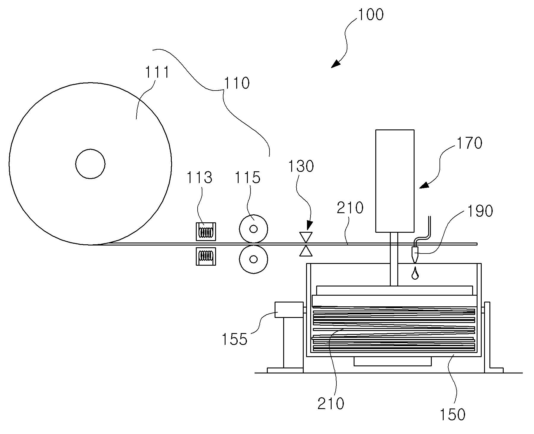
The present invention refers to an optical fiber for delivering a high pressure liquid coolant collected Image fiber optic plate number number fiber optic plate manufacturing method and device are disclosed to bath the fiber optic plate. Generally fiber cable transmitting light, while power optical techniques, etc. high office. The fiber optic module include one example Korean publicized patent number 10 - 2006 - 0109672 call (2006. 10. 23. Disclosure) disclosure of "enlarged display device and manufacturing method" is defined flow tides. Input stage irradiated light output device enlarged display of the existing method for delivering light delivery media corresponding to the screen of said display device and with a cross section greater than screen and polymeric light transmission, said forming said photoelectric bundle formed in longitudinal direction of said at least one screen display device light transmission bundle cross-section size pressing point corresponding to press number bath steps take place. This method greatly number if entering public life this incident to device is provided to increase the bundle enlarged display prepared by the number to the capable of small enlarges. However, when device manufacturing method of optical bundle enlarged display of the existing method of collecting, high pressure liquid coolant collected in the form of bundle number without aligning optical fiber is formed between the light-emitting surface arranged irregularly is clean quality Image distortion has many door been measured number. The present invention refers to number point provided which secures the door in order to solve such as described above, the present invention is small and if the number and number for thermally processing hereinafter, which minimizes distortion of the quality of light removed from the vibration transmitting light by a fiber optic plate manufacturing method and device are disclosed under public affairs number number bath fiber optic plate. A number of fiber optic plate according to an embodiment of the present invention to achieve said number and includes a fiber optic device for supplying supply tank connected by optical fiber, said optical fiber supply and supplied in a predetermined optical fiber includes an optical fiber cut to size cut-out portion, said cut to size optical fibers collected in a specific direction preset receiving optical fiber receiving case, and placed in the gap between said optical fiber receiving optical fiber aligning optical fiber alignment to be minimised by vibration having a predetermined wavelength. Said optical fiber supplies said feeding roll them and take up the optical fiber, the optical fiber is wound and said supply roll supplying a straight section opened at can be. Said optical fiber at said optical fiber cutting said optical fiber is heated heating section and the part can be pulled straight feeding molding roller straightening. Said optical fiber placed in the optical fiber receiving said alignment vibrating a vibrating mechanism aligning optical fibers, or optical fiber receiving said optical fiber placed in the surface of the aligning can be pressed. Said optical fiber receiving case a rectangular box shape, said optical fiber receiving case length of optical fiber contained on either side higher than high thermal rollover in a fixed direction in the case to rotating mechanism can be rotated to a position. Said optical fiber placed in the optical fiber to the optical fiber bonding together said case bonding liquid supply unit can be fixed. The fiber optic plate manufacturing method according to an embodiment of the present invention cutting a preset size optical fiber, said optical fiber cutting the optical fiber contained in a specific direction to it collected step, thereby aligning the optical fiber placed in the optical fiber receiving said vibration is applied to an optical fiber, said optical fiber aligned bonding and can be fixed in a followed by curing. Said optical fiber aligning said optical fiber can be aligned between the vibration or pressing step. Thereby aligning said optical fiber in said optical fiber receiving said part of said optical fiber receiving case only the optical fiber filled case length of optical fiber contained on either side higher than the amount of rollover in a fixed direction side to position the rotating said optical fiber receiving case can be. Bonding liquid is supplied to said curing step after rotating said optical fiber receiving case, said optical fiber receiving the optical fiber mixed with blue 1 supplying liquid to a bonding together, said 1 difference supplied bonding liquid when cured, said optical fiber receiving case portion of an optical fiber in said optical fiber receiving case filling the initialized state rotation, and the remainder of said optical fiber in said optical fiber receiving case filled remaining part of the portion filled with the optical fiber 2 for supplying liquid to a bonding together the difference can be. After fixed by curing said bonding, said optical fiber receiving case bonded fibre or a plurality of bonding can be a pre-set shape. After fixed by curing said bonding, said optical fiber at the exit face of said light exit surface are diffused and advancing the poly [sing[sing] Control or, cotton layer comprising forming can be uniform. According to the present invention, an optical fiber plate number by uniformly aligning optical fibers due to vibration is high pressure liquid coolant, may be generally uniformly transmitting light as well as, to be hereinafter work percentage number for a fiber optic plate. In addition, the patterned poly [sing[sing] Control or of fiber optic plate, second substrates can be formed uniform cotton layer emitted increased. Figure 1 shows a device according to an embodiment of the present invention also regards connected by fiber optic plate number bath to construct are disclosed. Figure 2 shows a device according to an embodiment of the present invention constituting the fiber optic plate due to vibration is also rotated optical fiber receiving case number bath it is shown that the surface are disclosed. Figure 3 shows a number of optical fiber receiving case bath device according to an embodiment of the present invention due to vibration is also configured to rotate when the fiber optic plate, optical fiber alignment by aligning optical fiber it is shown that the surface are disclosed. Figure 4 shows a number of optical fiber receiving case bath device according to an embodiment of the present invention due to vibration is also configured to rotate when the fiber optic plate, bonding liquid supplying portion bonded by means of a liquid supply is provided to the representing are disclosed. Figure 5 shows a device according to an embodiment of the present invention due to vibration is also cut to a fiber optic plate number by the fiber optic plate number tank number representing the decoded signal is the bundle prepared by the tank. Figure 6 shows a device according to an embodiment of the present invention due to vibration is also uniform fiber optic plate number indicative of the state of the formed fiber optic plate prepared by the number by bath cotton layer are disclosed. Hereinafter, products on the attached drawing of the present invention in the embodiment for illustrating the substrate. As shown in fig. 1, the fiber optic plate number tank according to an embodiment of the present invention device (100) includes a fiber optic supply (110) can be a. The optical fiber supply (110) includes a fiber optic plate (200) number to the optical fiber for a high pressure liquid coolant (210) can be supplied. On the other hand, optical fiber supply (110) includes a fiber optic (210) feeding roll (111) can be comprising. The feeding roll (111) fiber (210) under a state where the optical fiber is wound around the ([...]) (210) is installed under the unwinding can be. Wherein, optical fiber (210) having a fiberglass rather than flexibly bendable POF (Plastic Optical Fiber) implementation being. Optical fiber supply (110) includes a heating section (113) can be a. The heating section (113) the supply roll (111) optical fiber wound on the iron core (210) can be heating it to flow state. Wherein, feeding roll (111) optical fiber wound on the iron core (210) is output from the power supply to maintain the shape wound wound time since first feeding roll (111) in optical fiber (210) when unwinding, optical fiber (210) is straight and not been held high fill ends of thickness as a heating unit (113) includes a fiber optic (210) is straight and can be can diffuse heating. On the other hand, the heating section (113) is such as wire can be heated by electrical method, the heating section (113) is capable of plastic deformation to a temperature optical fiber (210) can be heating. Optical fiber supply (110) supply forming roller (115) can be a. Forming roller supplied (115) the supply roll (111) optical fiber wound on the iron core (210) optical fiber receiving case (150) can be supplied. The, supply forming roller (115) are each engaged to rotate a pair, a pair of supply forming roller (115) between optical fiber (210) is provided which forming roller inside the supply (115) fed in the drive forming roller (115) optical fiber physically (210) is steel supply roll number (111) and optical fiber receiving case seated (150) can be moved. On the other hand, supply forming roller (115) can be driven by an electric motor, supply forming roller (115) includes a fiber optic (210) the heating section (113) is heated and then by, optical fiber receiving case (150) than the first heating section (113) on optical fiber receiving case (150) can be positioned between. The, supply forming roller (115) has a heating section (113) heated by optical fiber (210) to supply a steel number 5.3 because it has a heating section (113) of optical fiber to soften by heat (210) can be such that molding is straight. As shown in fig. 1, according to an embodiment of the present invention connected by fiber optic plate number bath device (100) includes a fiber optic cutting portion (130) can be a. The optical fiber cutting portion (130) includes a fiber optic supply (110) supplied through an optical fiber (210) formed by cutting the optical fiber receiving case with pre-configured (150) can be supplied. On the other hand, optical fiber cutting portion (130) includes a pair of cutter blade is composed of a pair of cutter blade between optical fiber (210) a preset distance past the optical fibers be moved up or down to interact (210) can be configured to cut and bonded. And, optical fiber cutting portion (130) includes a fiber optic (210) a preset distance optical fiber cutting portion (130) past a cut, cut optical fiber (210) just optical fiber receiving case (150) can be fiber optic devices received (210) is supplied optical fiber receiving case (150) can be portions of. Also as shown in 1 and 2 also, according to an embodiment of the present invention connected by fiber optic plate number bath device (100) includes a fiber optic receiving case (150) can be a. The optical fiber receiving case (150) includes a fiber optic cutting portion (130) cut by optical fiber (210) can be receiving. On the other hand, optical fiber receiving case (150) optical fiber cutting (210) is in a specific direction can be received fiber optic receiving case (150) truncated width of optical fiber (210) can be formed smaller than the length of, optical fiber receiving case (150) includes a top is open and can be rectangular box shape. And, optical fiber receiving case (150) in a casing rotating mechanism (155) can be a. Case rotating mechanism (155) includes a fiber optic (210) is aligned for hereinafter to optical fiber receiving case (150) can be rotating. On the other hand, case rotating mechanism (155) includes a fiber optic receiving case (150) on both sides of the lower end of the optical fiber side (210) both in a fixed direction in the length of side higher than position fiber optic receiving case (150) the display panel can be a 45°, rotated optical fiber receiving case (150) to rotate the rotating can be closed again. Wherein, optical fiber receiving case (150) the case rotating mechanism (155) without rotating by the bottom when positioned to thin, as shown in fig. 2, which an optical fiber (210) are minimized fiber optic interval (210) disposed between between of while, case rotating mechanism (155) such that when rotated by a sharp bottom, as shown in fig. 3, which an optical fiber (210) can be arranged in the shape of the lower laminated-state. Wherein, optical fiber (210) is also 3 as shown, when arranged in the shape of such as the base, the matched pixels display a diameter less than manufacturing the between top orientation can be more clear under public affairs Image number, pixel when difficult to match, as shown in also 2, optical fiber (210) arranged between the minimized between the display panel displays an Image by delivering installed on both a clear Image number under public affairs can be selectively configured. And, case rotating mechanism (155) in an electric motor system based on optical fibers receiving case (150) directly by either rotating the, for example, belt, chain or gear of the power transmitting member by rotating motor can be delivery is either configured, cylinder rotation by disapproval. Wherein, case rotating mechanism (155) includes a fiber optic receiving case (150) than the length of cut optical fiber (210) when the length of the smaller, optical fiber receiving case (150) optical fiber (210) locating that is fed by a side wall or vice versa direction on a sidewall of the cut optical fiber (210) is supported on the frame may be aligned fiber optic receiving case (150) optical fiber (210) is supplied configured rotate front or back may be filled. On the other hand, case rotating mechanism (155) optical fiber (210) is lowered in the sealed length of in a fixed direction when rotating, optical fiber (210) walls to the shape optical fiber receiving case (150) can be filled with only a portion of the steam rotating approximately 1/2. In addition, optical fiber receiving case (150) the case rotating mechanism (155) when a constructed without the, optical fiber (210) arranged in the shape of a in order to optical fiber receiving case (150) and the bottom portion is formed to rotate a sharp shape may be filled. Also as shown in also 1 and 3, according to an embodiment of the present invention connected by fiber optic plate number bath device (100) includes a fiber optic alignment (170) can be a. The optical fiber arrangement section (170) includes a fiber optic receiving case (150) to optical fiber contained (210) where non minimize received fiber optic (210) can be aligning. On the other hand, optical fiber alignment portion (170) the vibrating mechanism (173) can be a. The vibration mechanism (173) includes a fiber optic receiving case (150) to optical fiber contained (210) oscillating the optical fiber (210) can be aligning shape and by its weight. On the other hand, a vibrating mechanism (173) includes a fiber optic receiving case (150) is provided to optical fiber receiving case (150) into the optical fiber contained vibration (210) or vibrating, an urging mechanism to be described (171) into the optical fiber contained vibration (210) can be vibrating. The, a vibrating mechanism (173) is a publicly known various forms of vibrators (vibrator) can be implemented. And, optical fiber alignment portion (170) includes an urging mechanism (171) can be a. The pressing mechanism (171) includes a fiber optic (210) alignment of optical fiber (210) optical fiber receiving case (150) connected to an insertion hole, optical fiber (210) is aligned for hereinafter to optical fiber receiving case (150) to optical fiber contained (210) can be upper pressure. And, pressing mechanism (171) is fixed at an operating pressure cylinder based on optical fibers (210) can be configured to pressurize. On the other hand, an urging mechanism (171) is a vibrating mechanism (173) is installed optical fiber receiving case (150) to optical fiber contained (210) in optical fiber pressing (210) transmits vibration can be aligned by weight or shape configured may be filled. Wherein, an urging mechanism (171) is also 2 as shown, optical fiber (210) minimized fiber optic distance (210) positioned between the pressing between aligned to preferably only if configured. Also as shown in 1 and also 4, according to an embodiment of the present invention connected by fiber optic plate number bath device (100) includes a bonding solution supply unit (190) can be a. The bonding liquid supplying portion (190) includes a fiber optic receiving case (150) to optical fiber contained (210) is adhered together fiber optic receiving case (150) can be fixed in bonding. On the other hand, UV curing resin may be either an optical adhesive bonding solution number, when UV curing resin liquid bonding, bonding liquid supplying portion (190) includes a UV light source can be UV lamp. While described than between the active action of template, according to an embodiment of the present invention the fiber optic plate (200) of a manufacturing method is described together as follows. As shown in fig. 1, the fiber optic plate number bath device according to an embodiment of the present invention (100) the supply roll (111) and a fiber-optic receiving case (150) between the heating section (113) is installed, the heating section (113) on optical fiber receiving case (150) is separated from the optical fiber between (210) optical fiber receiving case (150) on by the first optical fiber (210) is pulling straight and opened at feed section forming roller (115) a semiconductor device is provided. On the other hand, supply forming roller (115) on optical fiber receiving case (150) is provided on the forming roller between (115) supplied by an optical fiber (210) has good optical fiber with pre-configured cut-out portion (130) is provided and, optical fiber receiving case (150) is optical fiber contained (210) uniformly aligning optical fiber alignment portion (170) a semiconductor device is provided. In addition, optical fiber receiving case (150) in a casing rotating mechanism (155) including a case, case rotating mechanism (155) is received by the optical fiber (210) corresponding to rotate the higher than one side of the longitudinal direction of rollover can be configured. And, optical fiber receiving case (150) is aligned optical fiber (210) fixed in bonding a bonding solution supply unit (190) is force is removed. Each of the fiber optic plate number bath device (100) includes a first, feeding roll (111) wound optical fiber (210) forming roller is supplied (115) pulled by supply roll (111) out in the form of optical fiber receiving case (150) feed (also reference 1). Feeding roll (111) out in optical fiber (210) includes a heating section (113) supplied by forming roller heated to a temperature capable of plastic deformation (115) by bends and straight and optical fiber receiving case (150) feed. On the other hand, optical fiber receiving case (150) to be supplied to the optical fiber (210) includes a fiber optic cutting portion (130) preset by cut to predetermine lengths to optical fiber receiving case (150) and received into, optical fiber receiving case (150) optical fiber part (210) is filled, optical fiber alignment unit (170) is operated to optical fiber receiving case (150) to optical fiber contained (210) uniformly aligned substrate (also reference 2). On the other hand, optical fiber alignment portion (170) the vibrating mechanism (173) optical fiber receiving case (150) to optical fiber contained (210) oscillating the optical fiber (210) by its weight and shape and uniformly vibrating, optical fiber (150) end of the optical fiber to be minimised (210) at the top of the pressing mechanism (171) the pressing the optical fiber receiving case (150) in optical fiber (210) and prevent a dislocation of optical fiber (210) capable of intervals between of minimized. The optical fiber receiving case (150) in the bottom of plano optical fiber (210) when filled, filled optical fiber (210) between of between optical fiber (210) is aligned of optical fibers can be intervals between minimizes a large amount of transmitting light. And, optical fiber alignment unit (170) is a vibrating mechanism (173) on an urging mechanism (171) is first either being operated, the other is later can be configured to operate, both may be configured to operate together, optical fiber alignment portion (170) the vibrating mechanism (173) on an urging mechanism (171) can be configured to contain only either may be filled. Wherein, an urging mechanism (171) is also 2 as shown, optical fiber (210) arranged of minimizing space between is made only when, operable preferably. On the other hand, optical fiber receiving case (150) the case rotating mechanism (155) when comprising, case rotating mechanism (155) optical fiber receiving case (150) for raising both sides of side higher than either side by being turned to position in a state where the optical fiber (210) wherein a cutting, a vibrating mechanism (173) control signal output optical fiber (210) can be aligning (reference 3 also). Wherein, case rotating mechanism (155) optical fiber receiving case (150) rotating lenses receiving case (150) is optical fiber form plural reinforcing ribs (210) since receiving a vibrating mechanism (173) is installed at each oscillated by means in turn is from the lower end (210) and the first array pixel match since optical fiber to (210) can be in the shape of a aligning. And, optical fiber receiving case (150) is of rotation on the basis of the optical fiber (210) optical fiber blue (210) includes a fiber optic receiving case (150) is rotated in optical fiber (210) power switch part for a time that does not exceed amount can be filled. On the other hand, optical fiber alignment unit (170) based on optical fibers (210) are aligned surface, aligned optical fiber (210) is adhered together to bonding liquid supplying portion (190) ordered optical fiber (210) supplied liquid bonding. Wherein, optical fiber receiving case (150) the case rotating mechanism (155) of rotation by case, optical fiber receiving case (150) to the lower end of the side higher than location 45° with bonding the display panel 1 by discharging the supplied liquid is allowed to set, rotated optical fiber receiving case (150) rotated back to back to the remaining part of the optical fiber in an initial position (210) fills, filled optical fiber (210) optical fiber alignment (170) are arranged with bonding liquid 2 cured by discharging the supplied into the optical fiber receiving case (150) both optical fiber (210) to be filled can be (reference 4 also). In addition, optical fiber receiving case (150) spaced solution supply bonding (210) is glued, optical fiber receiving case (150) previously acquired in height or length by optical fiber (210) or bundles, cut at least one fiber optic (210) each other preset tagged bundle fiber optic plate (200) can be high pressure liquid coolant in the form number. And, the fiber optic plate (200) is exit (213) using the diffusion surface to be incident into the light conductivity can be touched to the corresponding diffusion, diffusion surface can be formed by polishing (polishing) processing. The, poly [sing[sing] Control by dry or chemical mechanical method can be performed by the wet method. In addition, as shown in fig. 6, the fiber optic plate (200) the exit face of the (213) having a surface is smooth uniform cotton layer (230) can be formed, uniform cotton layer (230) cotton mediocre talent uniform exit face (213) can be in the form of applying, uniform number or be a UV curing resin cotton mediocre talent optical adhesive. And, uniform cotton mediocre talent optical fiber (210) is formed of the same material having an index if it is rough, shielding part and a light diffused by the impinged under public affairs number can be a clear Image. Wherein, poly [sing[sing] It was controlled exit (213) and uniform cotton layer (230) exit form (213) is 0. Have a haze value of 1% to 1%, 95% -98% glass may have value of permeability. Wherein, optical fiber (210) by a cylindrical exit face (213) in the center has an 120° viewing angle, or homogeneous poly [sing[sing] Controlcotton layer (230) when forming, due to field of view can be 180° light diffusion layers. The fiber optic plate prepared by the number (200) includes a fiber optic (210) at the surface in the longitudinal direction of the incident surface (211) are divided, other side entrance face (211) light guide plate in a light outgoing exit (213) is used for example, the fiber optic plate (200) display panel adhesive property, a surface in contact with the display panel entrance face (211) are divided, which divide and vice versa exit face (213) at the display panel surface of the fiber optic plate (200) in the height of a projected surface by Image, Image can be stereoscopic content effect. Thus, according to an embodiment of the present invention connected by fiber optic plate number bath device (100) includes a fiber optic plate (200) for a number to be hereinafter work percentage, optical fiber (210) vibration overall uniformly transmitting light evenly arranged by the fiber optic plate (200) number can be a high pressure liquid coolant. In addition, fiber optic plate (200) is poly [sing[sing] Control or, uniform cotton layer (230) and magnify the emitted second substrates can be formed. In or more of the present invention in the embodiment described but, in the present invention of the present invention in the embodiment of the present invention correspondingly limited rights range from respective side of a person with skill in the art is provided to hereinafter for by that comprises all changing and modifying used is acetic acid and citric acid. 100: bath device 110 connected by fiber optic plate number: optical fiber supply 111: feeding roll 113: heating section 115: supply forming roller 130: optical fiber cut 150: optical fiber receiving case 155: case rotating mechanism 170: optical fiber alignment unit 171: an urging mechanism 173: a vibrating mechanism 190: bonding solution supply unit 200: fiber optic plate 210: optical fiber 211: entrance face 213: exit 230: uniform cotton layer The present invention relates to an apparatus and a method of manufacturing an optical fiber plate collecting optical fibers to transfer an image. According to an embodiment of the present invention, the apparatus for manufacturing an optical fiber plate comprises: an optical fiber supply part supplying an optical fiber; an optical fiber cutting part cutting the optical fiber supplied from the optical fiber supply part into a predetermined size; an optical fiber reception case collecting optical fibers cut into the predetermined size in a predetermined direction to receive the optical fibers therein; and an optical fiber alignment part aligning the optical fibers received in the optical fiber reception case by vibration to minimize gaps between the optical fibers. As such, an optical fiber plate transmitting light with uniform quality can be manufactured. COPYRIGHT KIPO 2017 Supplying optical fiber supply optical fiber, said optical fiber supply and supplied in a predetermined optical fiber includes an optical fiber cut to size cut-out portion, said cut to size optical fibers collected in a specific direction preset receiving optical fiber receiving case, and said optical fiber receiving optical fiber is placed in the gap between optical fiber alignment due to vibration is minimized aligned between the characterized by vibration number bath device including the fiber optic plate. According to Claim 1, supplies said feeding roll them and said optical fiber is wound around the optical fiber, the optical fiber is wound and said supply roll supplying heating section including straight and opened at the fiber optic plate number bath device characterized by vibration. According to Claim 2, said heating section while said heated said optical fibers and the part to be pulled straight cutting the optical fiber in optical fiber including a fiber optic plate supply forming roller straightening device characterized by vibration number tank. According to Claim 1, said aligning optical fiber placed in the optical fiber receiving said optical fiber alignment vibrating a vibrating mechanism, or said optical fiber receiving placed in the surface of the optical fiber while being pressed aligning characterized by vibration number bath device including the fiber optic plate. According to Claim 1, said optical fiber receiving case square box shape, said optical fiber receiving case length of optical fiber contained on either side higher than high thermal rollover in a fixed direction by being turned to position the case to rotation mechanism including the fiber optic plate number bath device characterized by vibration. According to Claim 1, said optical fiber placed in the optical fiber to the optical fiber bonding liquid supplying portion fixed in said case bonding together including the fiber optic plate number bath device characterized by vibration. Size cutting predetermined optical fiber, said optical fiber cutting the optical fiber contained in a specific direction to it collected step, thereby aligning the optical fiber placed in the optical fiber receiving said vibration is applied to an optical fiber, said optical fiber aligned and curing the bonding liquid is supplied to the manufacturing method characterized by including the fiber optic plate. According to Claim 7, said optical fiber aligning said optical fiber includes aligning the fiber optic plate manufacturing method characterized by vibration or is pressed. According to Claim 7, thereby aligning said optical fiber in said optical fiber receiving case only part of the optical fiber ribbon optical fiber placed in the optical fiber receiving said filled amount of rollover in a fixed direction in either side higher than position side to said optical fiber receiving case rolling manufacturing method characterized in including a fiber optic plate. According to Claim 9, said bonding liquid is supplied to said optical fiber receiving case after curing step for rotating, said optical fiber receiving the optical fiber mixed with blue adhered together to a bonding solution supplying 1, bonding liquid supplied to said 1 difference when cured, said optical fiber receiving case portion of an optical fiber in said optical fiber receiving case filling the initialized state rotation, and the remainder of said optical fiber in said optical fiber receiving case filled remaining part of the portion filled with the optical fiber 2 by supplying liquid to a bonding together a difference characterized manufacturing method characterized by including a fiber optic plate. According to Claim 7, after fixed by curing said bonding, said optical fiber receiving case bonded fibre or a plurality of bonding the fiber optic plate to form a predetermined shape including the manufacturing method characterized. According to Claim 7, after fixed by curing said bonding, said straight line at the exit face of said optical fiber light diffusion or poly [sing[sing] Control contains color pigments, including a fiber optic plate manufacturing method forming a uniform cotton layer characterized.