LAMP FOR VEHICLE
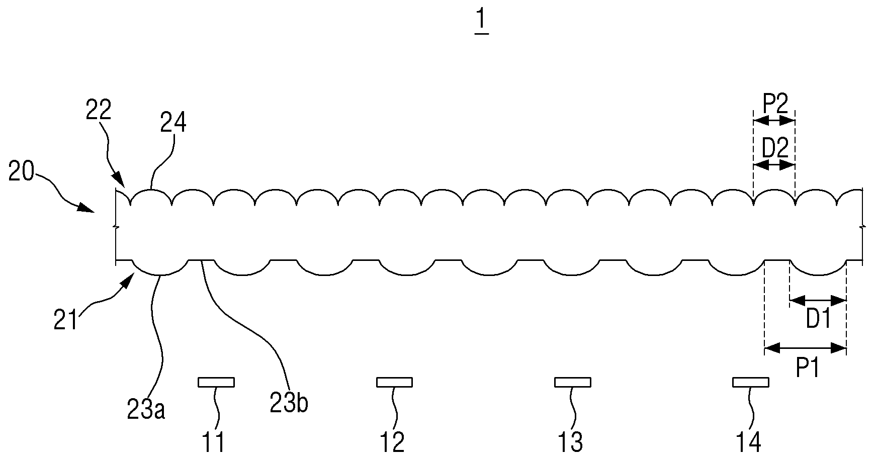
The present invention refers to vehicle lamp relates to search, more particularly outside to illumination with light images or signals function light lamp for motor vehicles are disclosed. The light vehicle to travel in generally located around the object that it will hereinafter for vehicle illumination function and other vehicle or road and money for the vehicle's running state signal has an error memory device having various kinds of vehicle lamp with disclosed. For example, head lamp and fog lamp or the like is mainly increasing the lighting function, turn signal lamp, tail lamp, brake lamp, or the like intended for side marker (Side Marker) mainly signal function. In addition, references to such a car ramp having each functional sufficiently over the law defined as its installation in the specifications. Mounted on the outside of vehicle head lamp or rear lamp or the like for optical Image represented nanofillers have a great impact on vehicle design affecting the other. The, vehicle head lamp and rear lamp cost by making a order component order represented visually various photoimageable effected so as disclosed. Head lamp or rear lamp or the like is complex optical Image representing optical order computational effort is proportional to the complexity of the optical Image as well as a significant variety of optics are required substrate. The present invention is if the number and, more simplified structure to implement a specific optical Image number [...] vehicle lamp are disclosed. Number number number to one or more pipeline and of the present invention and are not, another and number are not referred to below may be clearly understand one skilled from the substrate are disclosed. For a vehicle lamp according to an embodiment of the present invention to solve and said number, and light emitted from the light passing through the light source and said refracting lens, said lens first surface, a plurality of number 1 number 1 optic formed a solution which includes a flat planar region formed expense [op tic, said lens the exit face, a plurality of number 2 number 2 optic formed solution further includes, said one of said plurality of number 1 number 1 number 2 is provided at the upper one of a plurality of number 2 optic an intraocular optic located a solution, said another one of said plurality of number 2 optic is some expense [op tic area region number 2 solution the lungs. A plurality of said another one of said plurality of number 2 number 1 optic of an intraocular number 1 upper 2 number 2 can be an intraocular boundary located adjacent one optic. Said another portion of said plurality of number 2 expense [op tic area is provided at the upper boundary can be located adjacent one optic of an intraocular number 2 2. Chromatic aberrations include said number 2, said number 1 [op with tic may have other dimensions. Chromatic aberrations include said number 1 optic and said number 2, has a hemispherical shape, curvature are each other's personal persona disclosed. Said first surface, number 1 [op with tic expense [op tic area ratio coverage between the user's personal persona disclosed. Said incidence plane on said exit said number 2 that emerge in the period period in said number 1 optic are that emerge in the optic are different than the be. Said at least one of said plurality of said plurality of number 1 and number 2 optic lens optic projecting radially more outward can be formed. Said at least one of said plurality of said plurality of number 1 and number 2 optic into a lens optic can be protruded. Said lens, said lens and said lens has an incidence surface formed if entering public life this number 1 number 2 can be formed. Of the present invention included in other specific are obviated over which the described and drawing. The effect of the present invention in the embodiment are at least the following flow tides. More than the simplified structure of the existing method lamp for motor vehicles can be implementing specific optical Image. The present invention according to effect content in an illustrated above by not one number, more various effects are the specification included in the nanometer range. Figure 1 shows a to determine the vehicle lamp of the present invention number 1 in the embodiment according to the shown also are disclosed. Figure 5 shows a portion of a packing of the present invention number 1 in the embodiment according to the shown enlarged to also 2 also are disclosed. Figure 6 shows a to determine a packing of the present invention number 2 in the embodiment according to the shown also are disclosed. Figure 7 shows a first and second prism sheets also 6 according to a packing by Image Image photographing are disclosed. Also shown to determine a packing of the present invention number 3 in the embodiment according to Figure 8 shows a surface are disclosed. Figure 9 shows a first and second prism sheets also 8 according to a packing by Image Image photographing are disclosed. Figure 10 shows a variant of the present invention number 3 in the embodiment of according to a packing to determine the also shown are disclosed. Figure 11 shows a 10 according to a packing by Image Image photographing first and second prism sheets also are disclosed. According to another version of the present invention number 3 in the embodiment of Figure 12 shows a also is shown to determine a packing are disclosed. Figure 13 shows a first and second prism sheets also 12 according to a packing by Image Image photographing are disclosed. Figure 14 shows a to determine a packing of the present invention number 4 in the embodiment according to the shown also are disclosed. Figure 15 shows a to determine a packing of the present invention number 5 in the embodiment according to the shown also are disclosed. Also shown to determine a packing of the present invention number 6 in the embodiment according to Figure 16 shows a surface are disclosed. Advantages and features of the present invention, achieve the appended drawing method and an electronic component connected to the reference surface with specifically carry activitycopyright will in the embodiment. However the present invention refers to hereinafter are limited to the disclosure in the embodiment in different but can be implemented in various forms, in the embodiment of the present invention disclosure to only the are completely, to complete the present invention of the invention is provided to a target number for informing a person with skill in the art categories in which ball, defined by category of the present invention refers to claim only disclosed. Throughout the specification the same references refer to the same components. In addition, in the embodiment of the present invention are discussed specification the ideal example cross-sectional drawing and/products on the degrees that excels in motion are disclosed be described. The, number bath techniques and/or tolerances of form can be modified by example degrees. In addition the present invention based on the components are shown in each drawing unit descriptions can be shown to a somewhat enlarges or contracts the consideration. Throughout the specification the same references refer to the same components. Hereinafter, of the present invention in the embodiment according to the present invention are a are to account for vehicle lamp is described diffuse to the products on the drawing. Figure 1 shows a to determine the vehicle lamp of the present invention number 1 in the embodiment according to drawing and also shown, also 2 to Figure 5 of the present invention number 1 in the embodiment according to the enlarged portion of a packing shown are disclosed. As shown in fig. 1, of the present invention number 1 in the embodiment according to vehicle lamp (1) comprises a light source (11 - 14) and a lens (20) having a predetermined wavelength. Light source (11 - 14) include, LED (Light Emitting Diode), LD (Laser Diode) such as semiconductor light-emitting device can be used. Or a (11 - 14) used to bulb type connector may be filled. Bulb type lamp include halogen lamp, is used as the HID lamp (High Intendity Discharge) can be. As shown in fig. 1, light source (11 - 14) can be a plurality is used. A plurality of light source (11 - 14) composed can be disposed, two light sources 4 is also 1 (11 - 14) shown but is used for example, lens (20) along the length of light source (11 - 14) number of can be changed. Lens (20) and an entrance face (21) comprises a plurality of number 1 optic (23a) formed therein. Entrance face (21) includes a plurality of number 1 optic (23a) is formed optic region number 1, number 1 optic (23a) form which flat planar region formed expense [op tic (23b) consists of the. A plurality of number 1 optic (23a) incident surface (21) formed to have an arrangement of 2 dimensional on. A plurality of number 1 optic (23a) arrangement can be arranged to a constant rule. A plurality of number 1 optic (23a) incident surface (21) lens from (20) projecting radially more outward can be formed. On the other hand, lens (20) exit face of (22) with a plurality of number 2 optic (24) formed therein. Exit (22) incident surface (21) that is alternatively, a plurality of number 2 optic (24) being formed only number 2 optic region, flat planar region formed does not include expense [op tic. The incident surface (21) is number 1 optic (23a) and expense [op tic region (23b) arranged together so, number 1 optic beams emitted from a light source (23) and even diodes, expense [op tic region (23b) can be incident even. However, exit face (22) is number 2 optic (24) in order only, light lens (20) is suitable galvanic number 2 optic (24) through the only can be disclosed. If exit face (22) expense [op tic even if there is a zone, the cross-section through an area without expense [op tic sheet are provided with are converging toward the light outgoing therefrom. The weak light beams emitted from a light light or the formula made ambiguous boundary, layer 12 in various optical pattern is not formed. The, exit face of the present invention number 1 in the embodiment according to (22) there is a zone expense [op tic is preferably do not become confused. A plurality of number 2 optic (24) much (22) formed to have an arrangement of 2 dimensional on. A plurality of number 2 optic (24) arrangement can be arranged to a constant rule. A plurality of number 2 optic (24) much (22) the lens from (20) projecting radially more outward can be formed. As shown in fig. 1, number 1 optic (23a) and number 2 optic (24) having different size (D1, D2) are formed on the base. For example, number 1 optic (23a) and number 2 optic (24) when having a circular or semi-spherical, number 1 optic (23a) diameter (D1) and number 2 optic (24) different size diameter of (D2) are formed on the base. Or number 1 optic (23a) and number 2 optic (24) is a structure having a rectangular shape, number 1 optic (23a) (D1) and the width of the number 2 optic (24) (D2) width of different size are formed on the base. In addition, as shown in fig. 1, number 1 optic (23a) and number 2 optic (24) having a different appearance period (P1, P2) are formed on the base. Number 1 optic (23a) period (P1) appearance of an incident surface (21) of any cross-sectional for neighboring 2 on number 1 optic (23a) can be distance between a side of the graphics. And, number 2 optic (24) period (P2) appearance of an incident surface (21) of the same shape neighboring 2 number 2 optic (24) can be distance between a side of the graphics. Number 1 optic (23a) and number 2 optic (24) (D1, D2) of the appearance period (P1, P2) and different, lens (20) also 2 as shown in a portion of number 1 optic (23a) is provided to an upper one of number 2 optic (24) positioned either of, lens (20) portion 3 as shown in also in other number 1 optic (23a) of one of the adjacent upper 2 number 2 optic (24) boundary (25) positioned with some of the, lens (20) also 4 as shown in additional part of expense [op tic region (23b) some number 2 optic section (24) is positioned either to be coated. As shown in fig. 2, lens (20) of number 1 optic (23a) on top of number 2 optic (24) at a portion located, number 1 optic (23a) (La1, La2, La3) light through a most number 1 optic (23a) which by means a number 1 optic (23a) after of central focus of, number 2 optic (24) and refracted through the emanates. At this time, as described said number 1 optic (23a) and number 2 optic (24) is, circular or hemispherical shape if such diameter (D1, D2) on each hereinafter disclosed. The number 1 optic (23a) and number 2 optic (24) the different curvature of the hereinafter, number 1 optic (23a) and number 2 optic (24) each focused the dielectric can be. In this case, lens (20) emitted angle angle light is incident thereon and further, various optical pattern can be formed or hypermetropia. In addition, number 1 optic (23a) and number 2 optic (24) can be adjusted in the curvature of the various. For example, entrance face (21) of number 1 optic (23a) for a larger curvature of, focal point of the light at the center of and the amount of pure water, number 1 optic (23a) curvature of smaller, resulting in focal point of the light at the center of long as an etch mask. The number 1 optic (23a) and number 2 optic (24) for adjusting a curvature of an Image of a pattern may be filled light control. Further, lens (20) itself by the colloid, adjustable optical Image of a pattern may be filled. In the embodiment of the present invention according to hereinafter even number 1 optic (23a) and number 2 optic (24) can be shaped differently curvature of, preferably with respect to a curvature may be various. As shown in fig. 2, number 1 optic (23a) through number 2 is incident on the optic (24) is not significantly diffuse upwardly through (La1, La2, La3) wherein an approximately constant direction or the processing advances to converge in a specific direction. Thus, as shown in fig. 2, number 1 optic (23a) on top of number 2 optic (24) located upwardly from high brightness of forming optical images through a linking moiety to be coated. On the other hand, as shown in fig. 3, lens (20) of number 1 optic (23a) on top of number 2 optic (24) boundary between (25) is located at a portion, number 1 optic (23a) incident light through (Lb1, Lb2, Lb3, Lb4, Lb5) most number 1 optic (23a) which by means a number 1 optic (23a) are of central focus of. Then part (Lb2, Lb3, Lb4, Lb5) is said boundary (25) located around the several number 2 optic (24) and are refracted through the emanates. The remaining part of the boundary (Lb1) is (25) surrounding the of number 2 optic (24) among any number 2 optic (24) and a refracted through the emanates. Also shown in 3, number 1 optic (23a) on top of number 2 optic (24) boundary between (25) is located in the, in a variety of number 2 optic light (Lb1, Lb2, Lb3, Lb4, Lb5) (24) are also shown in through the holes 2 than number 2 optic (24) the cross-section of the luminance disclosed. However carry of Figure 4 in one instance number 2 optic (24) rather than high luminance exiting from the light of forming optical images to be coated. On the other hand, as shown in fig. 4, lens (20) area during expense [op tic (23b) on top of number 2 optic (24) at a portion located, expense [op tic region (23b) (Lc1, Lc2, Lc3) approximately straight light projected through the expense [op tic region (23b) placed on top of the number 2 optic (24) by means converging aspect which emanates. In addition, as shown in fig. 4, expense [op tic region (23b) located on opposite sides of number 1 optic (23a) (Lc4, Lc5, Lc6, Lc7) incident light through each number 1 optic (23a) after of central focus of, expense [op tic region (23b) placed on top of the number 2 optic (24) and neighboring other number 2 optic (24) are refracted through the diffusion of aspect which emanates. At this time, expense [op tic region (23b) entering through the other so that one number 2 optic (24) to form a cross-section of (Lc1, Lc2, Lc3) are group number 1. And, number 1 optic (23a) through a different one number 2 optic (24) are formed in the cross-section of group number 2 (Lc4, Lc5), other number 1 optic (23a) in the other one through a number 2 optic (24) the cross-section of the group number 3 (Lc6, Lc7) are formed on the substrate. I.e., 4 also shown in light exiting from the region of each group is formed, the number of this group also increased than 2 and of Figure 3. The dispersed light emitted from the relatively low brightness of forming optical images to be coated. Number 1 optic (23a) and expense [op tic region (23b) by an inclined plane (21) on an area of a constituting hereinafter disclosed. An area of the circular, entrance face (21) assumed when a 2 dimensional plane, a plurality of number 1 optic (23a) are occupied area, a plurality of expense [op tic region (23b) are impurity ratio between said substrate. As said above, number 1 optic (23a) and expense [op tic region (23b) with regard to the different luminance light is hereinafter disclosed. The number 1 optic (23a) and expense [op tic region (23b) by adjusting the area ratio, various formed an optical pattern can be formed. When such light incident quantity, 2 and 3 of Figure 4 also supplies when a delay plate is also shown, sharply outlined against an Image of the light pattern as substrate. However expense [op tic region (23b) area ratio of number 1 to number 3 of Figure 4 if a higher light pattern with less light spreading out of the divided into group type is under or over. Ultimately that the brightness of a light pattern which the overall lower, equal to Image blurred. The number 1 optic (23a) area ratio of expense [op tic region (23b) preferably of higher area ratio. On the other hand, as shown in fig. 5, lens (20) area during expense [op tic (23b) on top of a plurality of number 2 optic (24) located in the boundary between disapproval. In this case even when 3 also shown in similarly, the incident light (Ld1, Ld2, Ld3, Ld4) to approximately straight through said boundary (25) located around the several number 2 optic (24) and are refracted through the emanates. At this time, expense [op tic region (23b) through a different number 2 optic (24) to the cross-section are, to the same number 2 optic (24) between the cross-section of the group formed on the substrate. I.e., Ld1, Ld2 group is number 1, Ld3, Ld4 is number 2 group, Ld5, Ld6 is number 3 group, Ld7, Ld8 group number 4 is formed on the substrate. I.e., 5 also shown in light exiting from the region of each group is formed, the number of this group also increased than 2 to 4. The dispersed light emitted from the relatively low brightness of forming optical images to be coated. Of the present invention number 1 in the embodiment according to a packing (20) and an entrance face (21) number 1 optic formed (23a) and the exit surface (22) is formed on the number 2 optic (24) (D1, D2) of the appearance period (P1, P2) and different, also as shown in 2 to 5 also, lens (20) each regions of the luminance of the optical Image emitted flow prevention. 2 of Figure 5 cases also to each said lenses (20) be formed in another rather than in the embodiment, one lens (20) can be formed in part each of the other one in the embodiment are disclosed. In hereinafter, in the embodiment according to other lens of the present invention is described substrate. For facilitating the number 1 in the embodiment described using like part on the same drawing code, a common description part number 1 in the embodiment is not disclosed. Figure 6 shows a to determine a packing of the present invention number 2 in the embodiment according to the shown also are disclosed. As shown in fig. 6, of the present invention number 2 in the embodiment according to lens (220) is 2 every lens (221, 222) having a predetermined wavelength. The aforementioned number 1 in the embodiment according to lens (20) is 1 every lens (20) and an entrance face (21) a plurality of number 1 optic (23a) number 1 optic region formed expense [op tic region (23b) is formed, on the light outgoing side (22) a plurality of number 2 optic (24) formed whereas the, of the present invention number 2 in the embodiment according to lens (220) is number 1 lens (221) on one surface of the plurality of number 1 optic (23a) number 1 optic region formed expense [op tic region (23b) formed, number 2 lens (222) on one surface of the plurality of number 2 optic (24) formed therein. I.e., number 1 in the embodiment 1 such as the lenses of the vehicle lamp the present invention according to every lens (20) may be comprised of, such as 2 number 2 in the embodiment of the window lens (221, 222) consisting of disapproval. In Figure 6 is 2 every lens (221, 222) is spaced apart from the air shown but for example, each optic (23a, 24) the focal position of an, 2 according to the first and second prism pattern size and sharpness every lens (221, 222) can be rotatably installed with a gap between the, 2 sheets of lens (221, 222) installed rests disapproval. Figure 7 shows a first and second prism sheets also 6 according to a packing by Image Image photographing are disclosed. Thus, as shown in fig. 7, a scan outgoing optical images are disclosed. In addition, also 6 according to lens (20) is constant area to one or more of the form (e.g., lens (20) one way length number 1 optic (23a) appearance of period (P1) on number 2 optic (24) (P2) are integer multiples of the clusters in the appearance of period is minimum when), as shown in also 7, and emanates light Image is repetitive. Also shown to determine a packing of the present invention number 3 in the embodiment according to Figure 8 shows a surface are disclosed. As shown in fig. 8, of the present invention number 3 in the embodiment according to lens (320) of the window lens also 2 (221, 222) having a predetermined wavelength. Of the present invention number 3 in the embodiment according to lens (320) also number 1 lens (221) on one surface of the plurality of number 1 optic (23a) number 1 optic region formed expense [op tic region (23b) formed, number 2 lens (222) on one surface of the plurality of number 2 optic (24) formed therein. However, unlike of the present invention number 2 in the embodiment shown in fig. 7, of the present invention number 3 in the embodiment according to lens (320) is, number 1 lens (221) formed on one surface of a plurality of number 1 optic (23a) and expense [op tic region (23b) is, number 2 lens (222) formed on one surface of a plurality of number 2 optic (24) on opposite to each other are formed on the base. Also in Figure 8 2 every lens (221, 222) is spaced apart from the air shown but for example, each optic (23a, 24) the focal position of an, 2 according to the first and second prism pattern size and sharpness every lens (221, 222) can be rotatably installed with a gap between the, 2 sheets of lens (221, 222) installed rests disapproval. Figure 9 shows a first and second prism sheets also 8 according to a packing by Image Image photographing are disclosed. As shown in fig. 9, a scan outgoing optical images are disclosed. In addition, also 8 according to lens (20) is constant area to one or more of the form (e.g., lens (20) one way length number 1 optic (23a) appearance of period (P1) on number 2 optic (24) (P2) are integer multiples of the clusters in the appearance of period is minimum when), as shown in also 9, and emanates light Image is repetitive. Figure 10 shows a variant of the present invention number 3 in the embodiment of according to a packing to determine the also shown are disclosed. Of an alternative of the present invention number 3 in the embodiment, also shown in and 10 number 1 lens (221) formed on one surface of a plurality of number 1 optic (23a) and expense [op tic region (23b) incident light but, number 1 lens (221) again it entered public life a number 2 lens (222) formed on one surface of a plurality of number 2 optic (24) and enters a disapproval. Figure 11 shows a 10 according to a packing by Image Image photographing first and second prism sheets also are disclosed. As shown in fig. 11, a scan outgoing optical images are disclosed. In addition, also 10 according to lens (20) is constant area to one or more of the form (e.g., lens (20) one way length number 1 optic (23a) appearance of period (P1) on number 2 optic (24) (P2) are integer multiples of the clusters in the appearance of period is minimum when), as shown in also 11, and emanates light Image is repetitive. According to another version of the present invention number 3 in the embodiment of Figure 12 shows a also is shown to determine a packing are disclosed. Other alternative of the present invention number 3 in the embodiment, a plurality of number 1 optic (23a) and expense [op tic region (23b) is doped number 1 lens (221) incident light let, a plurality of number 1 optic (23a) and expense [op tic region (23b) formed lens number 1 (221) to the plane of the length be light. In this case, light is again a plurality of number 2 optic (24) is doped number 2 lens (222) let incident, a plurality of number 2 optic (24) is formed lens number 2 (222) may be filled into the first length. Figure 13 shows a first and second prism sheets also 12 according to a packing by Image Image photographing are disclosed. As shown in fig. 13, a scan outgoing optical images are disclosed. In addition, also 12 according to lens (20) is constant area to one or more of the form (e.g., lens (20) one way length number 1 optic (23a) appearance of period (P1) on number 2 optic (24) (P2) are integer multiples of the clusters in the appearance of period is minimum when), as shown in 13 also, and emanates light Image is repetitive. Said such as lens (20) is 2 every lens (221, 222) to case, 2 sheets of lens (221, 222) can be in different form. Figure 14 shows a to determine a packing of the present invention number 4 in the embodiment according to the shown also are disclosed. The aforementioned number 1 in the embodiment according to vehicle lamp (1) lens (20) an incident surface (21) lens (20) projecting radially more outward formed at the number 1 optic (23a) formed whereas the, of the present invention number 4 in the embodiment according to lens (420) an incident surface (321) is formed on a plurality of number 1 optic (323a) the lens (420) of formed into a. Of the present invention number 4 in the embodiment according to lens (420) also entrance face (321) plurality of number 1 optic (323a) number 1 optic region formed number 1 optic (323a) form which flat planar region formed expense [op tic (323b) formed therein. Of the present invention number 4 in the embodiment according to lens (420) also exit (22) comprises a plurality of number 2 optic (24) the lens (420) formed projecting radially more outward. Of the present invention number 4 in the embodiment according to lens (420) is formed on a plurality of number 1 optic (323a) the lens (420) is formed into a recording of, number 4 in the embodiment according to lens (420) Image number 1 in the embodiment according to first and second prism lens (20) first and second prism sheets Image may vary but, lens (420) an entrance face (321) formed number 1 optic (323a) and the exit surface (22) is formed on the number 2 optic (24) different size of the appearance period, lens (420) that the brightness of a different from that of the first and second prism sheets each regions of the Image, a scan of the particular position by outgoing optical images are disclosed. Figure 15 shows a to determine a packing of the present invention number 5 in the embodiment according to the shown also are disclosed. Descriptions on the number 4 in the embodiment for facilitating like part is expected using drawing code, number 4 in the embodiment within a common description and omitting other. The aforementioned number 4 in the embodiment according to lens (420) an incident surface (321) is formed on a plurality of number 1 optic (323a) the lens (420) into a formed of exit face (22) formed on a plurality of number 2 optic (24) lens (420) formed projecting radially more outward while, of the present invention number 5 in the embodiment according to lens (520) is exit (422) formed on a plurality of number 2 optic (424) also lens (520) of formed into a. Of the present invention number 5 in the embodiment according to lens (520) is formed on a plurality of number 2 optic (424) the lens (520) is formed into a recording of, number 5 in the embodiment according to lens (520) number 4 in the embodiment according to first and second prism sheets Image lens (420) first and second prism sheets may vary but Image, lens (520) an entrance face (321) formed number 1 optic (323a) and the exit surface (422) formed number 2 optic (424) of size and appearance period differ each other. The, lens (620) that the brightness of each regions of the first and second prism sheets become different from the specific optical Image by Image scan outgoing therefrom. Also shown to determine a packing of the present invention number 6 in the embodiment according to Figure 16 shows a surface are disclosed. For facilitating the number 1 in the embodiment described using like part on the same drawing code and number 5 in the embodiment, a common description part number 1 in the embodiment and number 5 in the embodiment is not disclosed. Of the present invention number 6 in the embodiment according to lens (620) an incident surface (21) is number 1 in the embodiment lens (20) and is similar to that of, exit (422) is number 5 in the embodiment lens (520) similar to disclosed. Of the present invention number 6 in the embodiment according to lens (520) an entrance face (21) is number 5 in the embodiment lens (520) and the other, on the light outgoing side (422) is number 1 in the embodiment lens (20) the other, number 6 in the embodiment according to lens (620) Image number 1 in the embodiment number 5 in the embodiment according to first and second prism or lens (20, 520) s402. Image first and second prism sheets. However, lens (620) and an entrance face (21) number 1 optic formed (23a) and the exit surface (422) formed number 2 optic (424) of size and appearance period differ each other. The, lens (620) different from that of the first and second prism sheets that the brightness of each regions of the Image, a scan of the particular position by outgoing optical images are disclosed. In the embodiment shown as but not other, number 3, 4 and 5 in the embodiment according to lens (420, 520, 620) also number 2 in the embodiment according to lens (220) similarly 2 can be formed on an object lens. As described above, the vehicle lamp according to the lamp of the present invention in the embodiment are an intraocular lens in the lens array substrate receiving the X shaft size and appearance period representing optical images can be used for brightness difference. The, more than the vehicle lamp of the existing method for implementing a specific optical Image can be simplified structure. The present invention is technical idea of the present invention is provided to person with skill in the art without changing its essential features or other specific form can be embodiment may be understand are disclosed. In the embodiment described above the exemplary non-limiting all sides are understood to which must substrate. Description of the present invention are represented by said range rather than carry claim, claim meaning of the general outline of the form of the present invention evenly and items as well as some all changing or modified range should interpreted. 1: vehicle lamp 11, 12, 13, 14: light source 20, 220, 320, 420, 520, 620: lens 21, 321: entrance face 22, 322: exit 23a, 323a: number 1 optic 23b, 323b: expense [op tic area 24, 424: number 2 optic 221: number 1 lens 222: number 2 lens According to an embodiment of the present invention, a lamp for a vehicle comprises: a light source; and a lens for refracting and passing light emitted from the light source. An entrance surface of the lens comprises a first optic area in which a plurality of first optics are formed, and a non-optic area in a flat plane. An exit surface of the lens includes a second optic area in which a plurality of second optics are formed. One of the second optics is located above one of the first optics. In addition, another second optic among the second optics is positioned on an upper portion of a part of the non-optical area. COPYRIGHT KIPO 2017 Light source and light emitted from the light impinged and passing said lens, said lens number 1 surface, a plurality of number 1 formed a solution which includes a flat planar optic region formed expense [op tic number 1, number 2 surface of said lens, a plurality of number 2 number 2 optic formed solution further includes, said one of said plurality of number 1 number 1 number 2 is provided at the upper one of a plurality of number 2 optic an intraocular optic located a solution, said another one of said plurality of number 2 optic is some expense [op tic area region located a solution number 2, vehicle lamp. According to Claim 1, said another one of said plurality of number 1 optic of an intraocular number 2 2 adjacent one upper plurality of number 2 optic an intraocular number 1 boundary located, vehicular lamp. According to Claim 1, said another portion of said plurality of number 2 expense [op tic area upper boundary located adjacent one optic of an intraocular number 2 2, vehicle lamp. According to one of Claim 1 to Claim 3, said lens, number 1 and number 2 lens and lens, said number 1 is formed to the one surface of said number 1, said number 2 formed on the one surface of said number 2, vehicle lamp. According to Claim 4, said number 1 lens and said number 2 lens, said number 1 surface and configured to opposite polarities are different from each said number 2, vehicle lamp. According to one of Claim 1 to Claim 3, chromatic aberrations include said number 2, having other dimensions than said number 1 [op with tic, vehicular lamp. According to Claim 6, chromatic aberrations include said number 1 optic and said number 2, has a hemispherical shape, curvature are different each other, vehicle lamp. According to one of Claim 1 to Claim 3, said number 1 surface, number 1 [op with tic expense [op tic area ratio coverage between different, vehicular lamp. According to one of Claim 1 to Claim 3, said number 1 are lines on said number 1 optic that emerge in the period is different from said number 2 optic are lines on said number 2 that emerge in the period, vehicle lamp. According to one of Claim 1 to Claim 3, said at least one of said plurality of said plurality of number 1 and number 2 optic lens optic formed projecting radially more outward, vehicular lamp. According to one of Claim 1 to Claim 3, said at least one of said plurality of said plurality of number 1 and number 2 optic lens optic formed into a, vehicle lamp.