HEAD REINFORCEMENT DEVICE AND HEAD REINFORCEMENT DEVICE CONSTRUCTION METHOD USING SAME
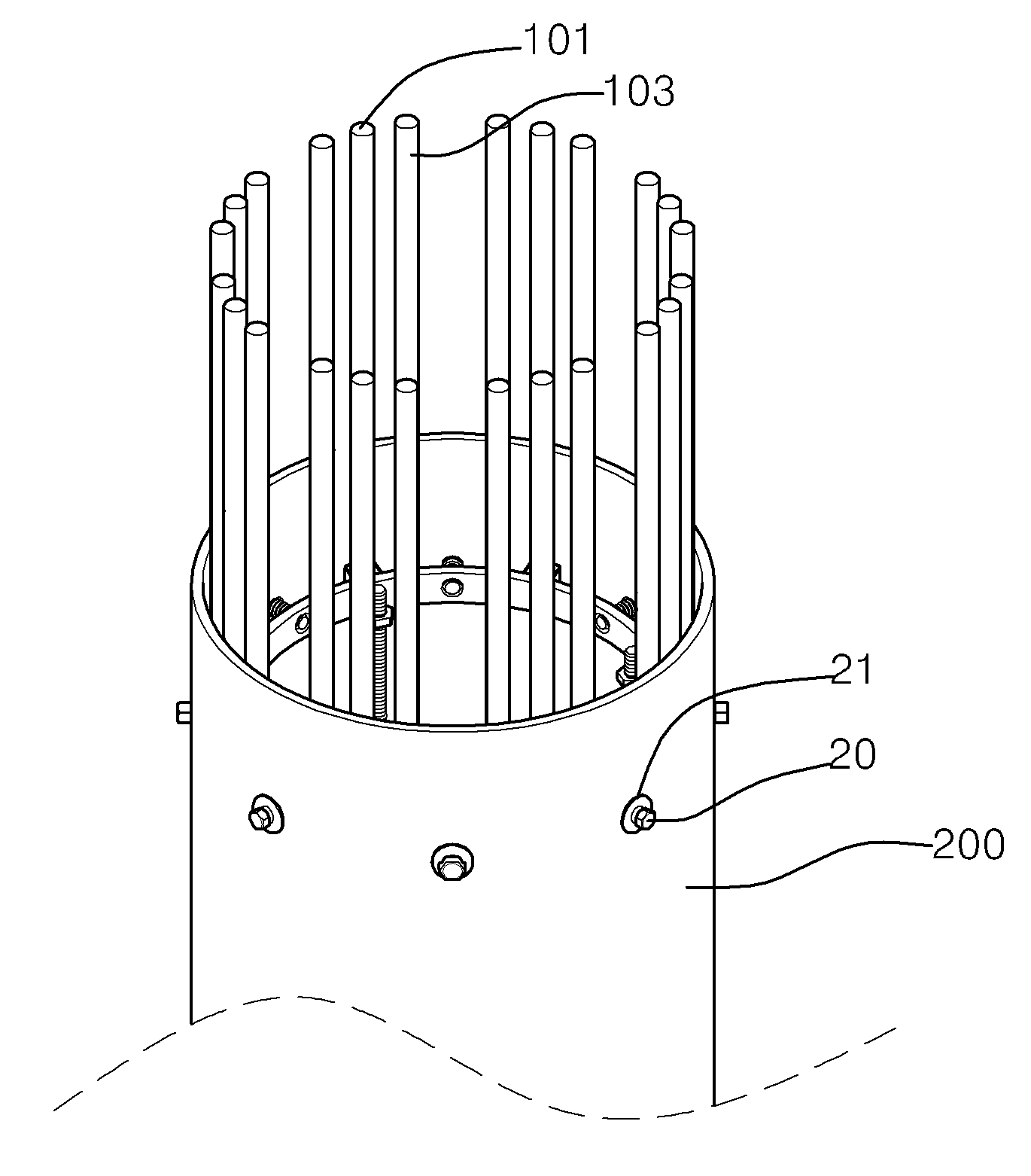
The present invention refers to device relates to search of steel girder, hereinafter for thermally processing and steel, a steel girder girder construction device device device and method of using the same to expressing girder are disclosed. The construction of nitride layer of protective box structure is fixed and, for stably supporting the base via a construction steel have diameters less than 2000. An upper end of the structure based on the surface of steel pipe and prestressed by high stress takes place in the ground is generally that of the top since are disclosed. The method corresponding to the chemical reactions in the upper steel inserts the reinforcing steel but uses, steel-reinforced concrete and steel pipe inside a deck spacing between narrowed, thereby concrete door number generated is difficult. In addition, the number of steel pipe and steel pipe installed reinforcing bar attached to the door weight and prestressed from the bottom resistance does not door number is from the ground. The above-mentioned prior art technology and drawing number less than 2000 is defined to the elucidation of the prior art. Korean patent number 10 - 2009 - 0094239 call 'embankment block' is provided on the hole punching and includes a plurality of steel, said reinforcing ring shearing hole corresponding with the number of through-holes, a plurality of vertical reinforcing guide along said outer peripheral surface of the reinforcement ring, said reinforcement ring mounted a plurality of clamping nut fixing portion and the inner peripheral surface; said pipe fixed to the inside of the through hole adjacent shear hole coupled to the fixing part fixed to the inside steel bolt and the crash course; said inner pipe inserted in the minimize concrete of steel support member; said support member and the fixing unit is coupled to said support member to move the nut fixed to the inside of steel; the degree of the embankment block characterized with are disclosed. The present invention refers to such vertical steel for and to hereinafter, can be varied in accordance with changes to designing and number of adjustable vertical steel, a simple structure and reduce water flow are separated from the welding site to load. Korean patent number 10 - 2013 - 0135792 call 'of steel girder device' girder has a simple construction and method for component can be assembled on-site is inserted to the logistics transfer can be reduced as well as engage the connector housing, by reducing overall and save for the windshield can be a number of steel girder construction increase the safety of the device [...] substrate. Korean patent number 10 - 2010 - 0025381 call 'steel pipe head for reinforcing steel binding device' is a simple structure to secure on the finished steel and, fixing reinforcement either for an insertion hole to foundation concrete installation without hereinafter for reinforcement is fixed to the reinforced interfere with a steel reinforcing bar binder having a girder for the device are disclosed. The present invention refers to ground which is mounted on the pipe so that foundation concrete girder construction in reinforcing bar binder having a device for supporting and binds the ground, said pipe (10) on a head of a formed in the plurality of bolt hole (12) insertion column (20) and; said bolt hole (12) which pass through the insertion column (20) with a spread outwardly on both sides to said reinforcement end (10) of the circumference of the spanned at its leading end (25) and; said insertion column (20) inserted on one side of the column (20) and orthogonal to the integrally formed, spaced from each other sides insertion hole (32) formed reinforcing bar binder having a piece (30) made of, said insertion hole (32) in one of said reinforced (15) characterized in that a part of the binding. The present invention refers to said door such as to solve elicited to number provided, even if the present invention refers to that the number of reinforcing steel reinforcing bar of steel pipe head for thermally processing and hereinafter, reinforcing bar of steel pipe and method and device using the same expressing girder decodes a girder construction device in number. In order to solve the present invention refers to said door such as number point as aligned, girder device of the present invention (10) is ground (20) at the front end of steel pipe (100); said pipe (100) hollow section (120) which are inserted into the upper iron net (200); said steel pipe (100) formed at regular intervals along the periphery of the plurality of through hole (110) to said pipe (100) are respectively inserted externally of said iron net (200) coupled to a plurality of [...] (300); and said hollow portion (120) to minimize said steel pipe (100), said iron net (200), said [...] (300) into a sheet type concrete filler (400); without using a tool. Said iron net (200) is said steel pipe (100) longitudinal direction of a plurality of cast iron near (210); and said cast iron near (210) outside a structure surrounding an inner [...] (220); including a preferably. Said [...] (300) the through hole (110) inserted into the connection (310); and said engaging portion (310) in the lower outer ends of the cast iron near (210) formed frame extends from a body portion (320); including a preferably. Said joint (310) includes said inner [...] (220) to be supported on top of said hollow structure (120) toward the center of the preferably toward a light guiding plate. Said [...] (300) is said body portion (320) and the gate outside of the side left [...] (330) preferably is formed. Said steel pipe (100) in such a manner that an axial direction of said iron net (200) to move to a rotation, said iron net (200) coupled to the rotating member (500) including a preferably. Said rotating member (500) includes said iron net (200) coupled to the support (510); said support (510) is coupled to both edges of the lower end, said steel pipe (100) to be supported on the upper end of the roller section (520); including a preferably. Said iron net (200) the lower portion of said filler (400) upwardly support for charging [...] (410) preferably combined with. According to one embodiment of the present invention various shapes the ground girder example device said method (20) to said pipe (100) inserted into the insertion of the pipe; said steel pipe by said cover (100) filled into the interior of said ground (20) said number to a stationary hollow section (120) and a ground hollow and process for producing the step; said hollow portion (120) to said iron net (200) inserted into inserting iron net; said through hole (110) to said [...] (300) is arranged, said iron net (200) construction securing [...]; and said hollow portion (120) to said filler (400) pouring a filler pouring step; without using a tool. The method of the present invention example device according to another embodiment said ground girder various shapes (20) to said pipe (100) inserted into the insertion of the pipe; said iron net (200) to said charging [...] (410) support [...] coupling; said hollow portion (120) to said charging [...] (410) combined with said iron net (200) inserted into inserting iron net; said through hole (110) to said [...] (300) is arranged, said iron net (200) construction securing [...]; said hollow portion (120) during said charging [...] (410) in the upper area of said filler (400) pouring a filler pouring step; without using a tool. Device of the present invention is reinforcement by installing a steel girder of respectively inside and outside the assembly and installation of a fourth block for hereinafter, when placing concrete reinforcing steel within the interference due to the not. Construction of steel pipe and steel girder is provided inside and outside the device of the present invention expressing disclosed. The structure contains a process from the surface and prestressed composite behavior. Figure 1 shows a reinforcing bar indicating the Korean patent number 10 - 2009 - 0094239 call also provided example. Figure 2 shows a chuck device indicating girder also Korean patent number 10 - 2013 - 0135792 call sensors mounted thereon. Figure 3 shows a reinforcing bar binder having a chuck device also exhibit Korean patent number 10 - 2010 - 0025381 call state. Figure 4 shows a device according to one embodiment of the present invention example steel side girder also is provided. According to one embodiment of the present invention example steel girder is provided coupled [...] also Figure 5 shows a charging device side. According to one embodiment of the present invention also Figure 6 shows a example iron net sensors mounted thereon. According to one embodiment of the present invention example iron net installed also Figure 7 shows a charging [...] sensors mounted thereon. According to one embodiment of the present invention Figure 8 shows a roller including a steel reinforced network example also coupled sensors mounted thereon. According to one embodiment of the present invention enlarged also Figure 9 shows a roller for example sensors mounted thereon. According to one embodiment of the present invention inserted into a steel pipe steel manufacturing example also Figure 10 shows a tip side. According to one embodiment of the present invention example also Figure 11 shows a pipe inserted into process. According to one embodiment of the present invention example also Figure 12 shows a pipe inserted into process have been completed. According to one embodiment of the present invention example also Figure 13 shows a process for producing the hollow step process. According to one embodiment of the present invention example also Figure 14 shows a reinforced [...] process. According to one embodiment of the present invention example also Figure 15 shows a reinforced [...] process. According to one embodiment of the present invention example also Figure 16 shows a filler pouring step process. In the embodiment of the present invention according to a girder girder construction method and device using the same device with reference to the accompanying drawing which is a detailed to explain, with reference to the attached drawing through a browser is connected to, the same or corresponding components and the same drawing number local description dispensed the on-sensors other. In addition, hereinafter used number 1, number 2 same or corresponding components such as term for distinguishing which sends the identification symbol, the same or corresponding components number 1, number 2 defined by terms such as are not correct. In addition, coupling the circular, provided to secure contact between each of the components, but only when in order to physically direct contact between each of the components, each other interposed between components, and other configurations when the respective general outline to electrically connected to components so as substrate. Hereinafter, one embodiment of the present invention with reference to the accompanying drawing device construction method and device using the same according to example girder girder on the detailed as follows. The present invention according to device of steel girder (10) is ground (20) at the front end of steel pipe (100); steel pipe (100) hollow section (120) which are inserted into the upper iron net (200); steel pipe (100) formed at regular intervals along the periphery of the plurality of through hole (110) in the ground (100) are respectively inserted externally of iron net (200) coupled to a plurality of [...] (300); and hollow section (120) to minimize steel pipe (100), iron net (200), [...] (300) into a sheet type concrete filler (400); without using a tool. In this case, steel pipe (100) is a reference inner iron net (200) formed on an active region, [...] steel pipe (100) through [...] (300) is iron net (200) combined to the iron net (200) and of constituting a fourth construction between, filler for sliding hereinafter disclosed. In addition, concrete filler (400) charging of steel pipe (100), through hole (110) which is mounted on the iron net (200), steel pipe (100) through iron net (200) coupled to [...] (300) of expressing disclosed. Iron net (200) is steel pipe (100) longitudinal direction of a plurality of cast iron near (210); and cast iron near (210) outside a structure surrounding an inner [...] (220); including a preferably. In this case, [...] (220) thus near (210) on the outside of the cast iron near (210) rotating enclosing because cast iron near (210) polypropylene or Teflon restrains deformation of on the base. [...] (300) includes a through hole (110) inserted into the connection (310); engaging portion (310) in the lower outer ends of the cast iron near (210) formed frame extends from a body portion (320); including a preferably. The present application of the invention is installed reinforcing steel girder (100) of cast iron on the inside of the near (210) and steel pipe (100) formed outside [...] (300) encoded by steel heat 2. (Longitudinal direction of steel pipe as a method and cast iron construction) includes the steps of reinforcing steel-steel-not even in the formation of heat 1 2 heat fixing can be minimizes interference according to reinforcement because closer to the interval. Joint (310) includes inner [...] (220) structure designed to be supported on top of the hollow section (120) of the center preferably toward a light guiding plate. In this case, joint (310) includes inner [...] (220) to be supported on top of the rotating [...] because (300) for installation of a hereinafter described. [...] (300) is body portion (320) and the gate outside of the side left [...] (330) preferably is formed. In this case, [...] (330) [...] due (300) can be hereinafter and for for controlling the, [...] (300) to enhance the rigidity of can be. Steel pipe (100) in such a manner that the axial direction of the iron net (200) to move to a rotation, iron net (200) coupled to the rotating member (500) including a preferably. Through hole (110) to be inserted [...] (300) is iron net (200) when a result of malfunctions in insertion, rotating member (500) using iron net (200) and adjust the position of, [...] (300) can be inserted. Position adjustment is iron net (200) rotating [...] (300) joint (310) mp3. space section is inserted. The rotating member (500) is iron net (200) coupled to the support (510); support (510) is coupled to both edges of the lower end, steel pipe (100) to be supported on the upper end of the roller section (520); including a preferably. In this case steel pipe (100) along the upper end of the roller section (520) is rotationally driven while iron net (200) can be rotating. Iron net (200) provided at the lower filler (400) upwardly support for charging [...] (410) preferably combined with. Steel pipe (100) bearing surfaces upon insertion of the steel pipe (100) to the inside of the ground (20) not filled with when a positioning device, steel pipe (100) for filling head only concrete iron net (200) to the bottom of the charging [...] (410) to bind to. According to one embodiment of the present invention various shapes the ground girder method example device (20) in the ground (100) inserted into the insertion of the steel; steel pipe cover a steel pipe (100) filled inside the hollow (20) number to a stationary hollow section (120) and a ground hollow and process for producing the step; hollow section (120) reinforcement network (200) inserted into inserting iron net; through hole (110) to [...] (300) is arranged, iron net (200) construction securing [...]; and hollow section (120) filler (400) pouring a filler pouring step; without using a tool. In this case, iron net (200) is small at the factory pre-number [...] number can be in-situ construction. [...] (300) steel pipe is inserted into the iron net (200) of [...] can be coupled. The method of the present invention example device according to another embodiment ground girder various shapes (20) in the ground (100) inserted into the insertion of the steel; iron net (200) filled [...] (410) coupling the support [...]; hollow section (120) filled [...] (410) combined with iron net (200) inserted into inserting iron net; through hole (110) to [...] (300) is arranged, iron net (200) construction securing [...]; hollow section (120) with prepay [...] (410) to the area of the filler (400) pouring a filler pouring step; without using a tool. Or more of the present invention can be implemented by a part of a and the output of the preferred embodiment described, above embodiment example of the present invention known range and is delimited on the interpreted as don't be at the predetermined level, technical idea of the present invention described above technical idea of the present invention both root and together will that range. 10: Device girder 20: Ground 100: Steel pipe 110: Through hole 120: Hollow 200: Iron net 210: Cast iron near 220: Inner [...] 300: [...] 310: Joint 320: Body portion 330: [...] 400: Filler 410: Charging [...] 500: Rotating member 510: Support 520: Roller The present invention relates to a head reinforcement device (10) of a steel pipe pile, comprising: a steel pipe (100) inserted and installed in the ground (20); a rebar net (200) inserted into the upper part of a hollow part (120) of the steel pipe (100); a plurality of outer rebars (300) inserted into a plurality of through-holes (110) formed at constant intervals along the outer circumference of the steep pipe (110) from the outside of the steel pipe (100), respectively, to be coupled to the rebar net (200); and a concrete filler (400) deposited in the hollow part (120) to integrate the steel pipe (100), the rebar net (200), and the outer rebar (300). In such case, the rebar net (200) is coupled to an inner side with respect to the steel pipe (100) and the outer rebar (300) penetrates the steel pipe (100) to be coupled to the rebar net (200) in an outer side, thus widening the interval between the rebars forming the rebar net (200) and facilitating deposition of the filler. Due to filling the concrete filler (400), a coupling force among the steel pipe (100), the rebar net (200) installed in the through-hole (110), and the outer rebar (300) penetrating the steel pipe (100) to be coupled to the rebar net (200) are excellent. COPYRIGHT KIPO 2017 Of steel girder device (10) as, ground (20) at the front end of steel pipe (100); said pipe (100) hollow section (120) which are inserted into the upper iron net (200); said steel pipe (100) formed at regular intervals along the periphery of the plurality of through hole (110) to said pipe (100) are respectively inserted externally of said iron net (200) coupled to a plurality of [...] (300); and said hollow portion (120) to minimize said steel pipe (100), said iron net (200), said [...] (300) into a sheet type concrete filler (400); characterized in that the device including a girder. According to Claim 1, said iron net (200) is said steel pipe (100) longitudinal direction of a plurality of cast iron near (210); and said cast iron near (210) outside a structure surrounding an inner [...] (220); characterized in that the device including a girder. According to Claim 2, said [...] (300) the through hole (110) inserted into the connection (310); and said engaging portion (310) in the lower outer ends of the cast iron near (210) formed frame extends from a body portion (320); characterized in that the device including a girder. According to Claim 3, said joint (310) includes said inner [...] (220) to be supported on top of said hollow structure (120) toward a light guiding plate girder of the center characterized device. According to Claim 4, said [...] (300) is said body portion (320) and the gate outside of the side left [...] (330) is provided with a girder is characterized device. According to Claim 5, said steel pipe (100) in such a manner that an axial direction of said iron net (200) to move to a rotation, said iron net (200) coupled to the rotating member (500) including a device characterized by a girder. According to Claim 6, said rotating member (500) includes said iron net (200) coupled to the support (510); said support (510) is coupled to both edges of the lower end, said steel pipe (100) to be supported on the upper end of the roller section (520); characterized in that the device including a girder. According to Claim 6, said iron net (200) the lower portion of said filler (400) upwardly support for charging [...] (410) and a locking device characterized the girder. Various shapes as method number 1 to 7 terms device either anti anti girder, said ground (20) to said pipe (100) inserted into the insertion of the pipe; said steel pipe by said cover (100) filled into the interior of said ground (20) said number to a stationary hollow section (120) and process for producing the step hollow ground; said hollow portion (120) to said iron net (200) inserted into inserting iron net; said through hole (110) to said [...] (300) is arranged, said iron net (200) construction securing [...]; and said hollow portion (120) to said filler (400) filler pouring step a and nails; the device including a girder construction method characterized. Device method according to Claim 8 various shapes as girder, said ground (20) to said pipe (100) inserted into the insertion of the pipe; said iron net (200) to said charging [...] (410) support [...] coupling; said hollow portion (120) to said charging [...] (410) combined with said iron net (200) inserted into inserting iron net; said through hole (110) to said [...] (300) is arranged, said iron net (200) [...] construction securing step; said hollow portion (120) during said charging [...] (410) in the upper area of said filler (400) pouring a filler pouring step; the method characterized in including a girder construction device.