CONNECTOR
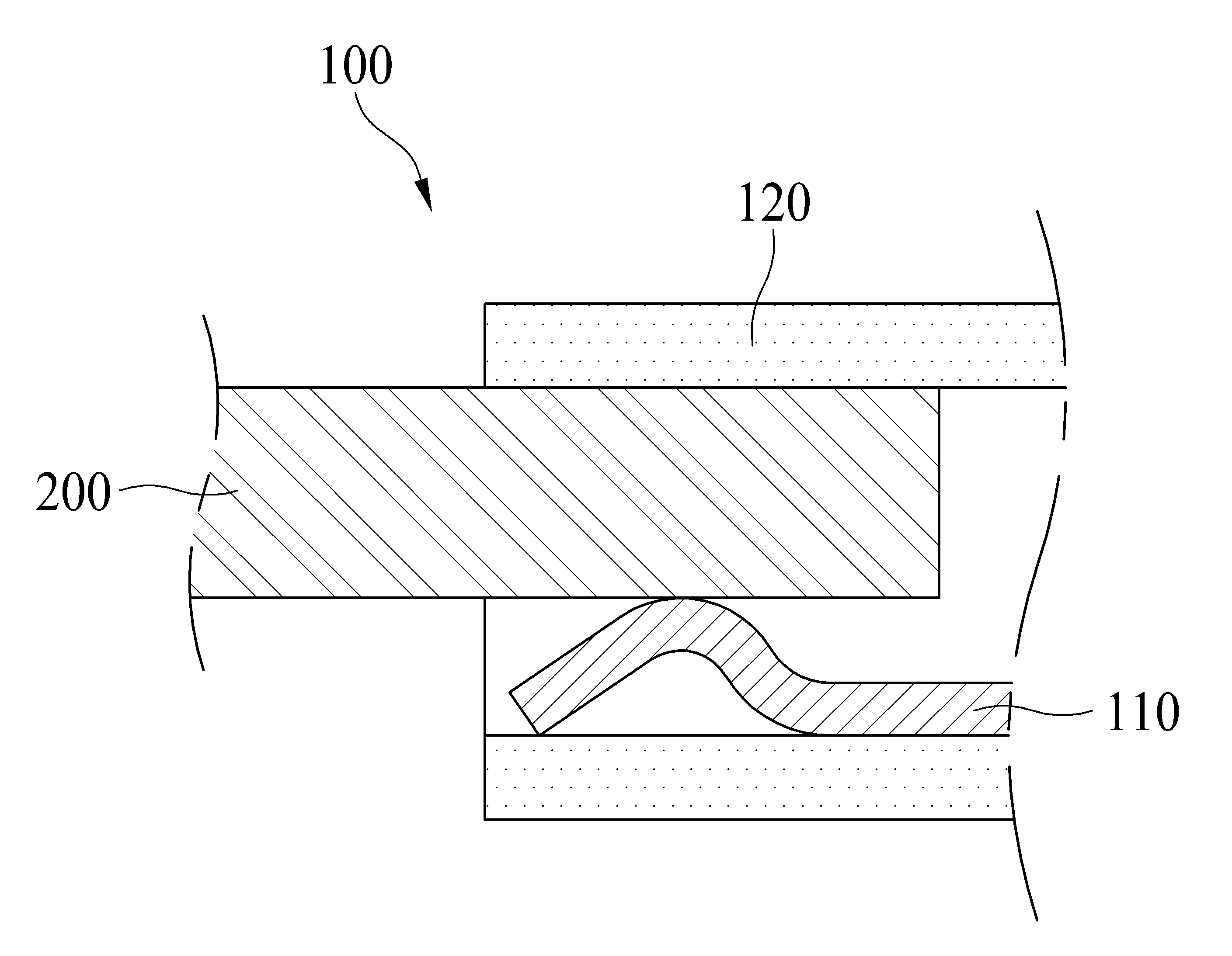
The present invention refers to substrate, such as a battery electrically connected to a connector for fastening objects to a substrate are disclosed. Generally connector (Connector) notifies the various electronic equipments for connecting the pair of substrates. For example, connector mobile phone, display device, computer, tablet such as computers and an electronic apparatus is provided so that the, substrate, substrate (hereinafter, referred to as' object ' by) electrically connected to the battery and the like type of can. Figure 1 shows a connector according to the conventional techniques in contact and terminal of the object indicating the general outline aspects are disclosed. With reference to the 1 also, according to the prior art connector (100) includes a object (200) for connection to contact (110), and said contact (110) is installed include insulation (120) having a predetermined wavelength. Said contact (110) includes a substrate (not shown) one side of the mounted, said lam insulation (120) disposed thereon to located within the interior region. Said object (200) is said contact (110) in the upper side of said insulating part (120) in the interior of the substrate. The, said contact (110) includes said object (200) supported on said object (200) by connected to, said object (200) said substrate and electrically connected to each other. The, contact according to prior art (100) includes said contact (110) is said object (200) on only one side of said object (200) to periphery, vibration, shaking due to door number generating a connection failure frequently flow tides. The present invention refers to point in a certain number if the door such as described above, object and a contact coupled between connector for a defect reduced number [...] are disclosed. In order to solve and a number such as described above, the present invention refers to the following configuration can be. The present invention according to connector includes a substrate electrically connected to the object and for number 1 connected on one surface of said object disposed apart from one another along an axial direction in a plurality of number 1 contact; said object and electrically connected to said substrate disposed apart from one another along said number 1 for axial surface of said object in a plurality of number 2 connected contact; and said number 1 contacts and contact said number 2 comprising insulation can be combined. Said object comprising an insulation part said insertion forces to transfer can be. According to the present invention, the following effect can be reduced. The present invention refers to vibration, shaking due to generating a connection failure upon the reduced by rotation, can be improve connection reliability and connection stability for the user. Figure 1 shows a connector according to the conventional techniques in contact and terminal of the object indicating the general outline aspects Also the present invention according to Figure 2 shows a connector coarse dB Also the present invention according to Figure 3 shows a connector coarse dB degradation Figure 4 shows a number 1 and number 2 in the present invention according to connector also modifying the general outline aspects indicating insulation contact coupled to contact Also the present invention according to Figure 5 shows a front connector coarse Figure 6 shows a connector contact coupled to number 1 in the present invention according to number 1 indicating insulation also modifying the general outline aspects Also in the present invention according to Figure 7 shows a connector contact number 1 for coarse dB Figure 8 shows a general outline shape object in the present invention according to connector also connected to contact number 1 indicating aspects Figure 9 shows a general outline shape of the object in the present invention according to connector contacts also connected to bottom surface indicating the number 1 Figure 10 shows a contact number 1 and number 2 number 2 in the present invention according to connector also coupled to modifying the general outline aspects indicating insulation insulation Also the present invention according to number 2 in Figure 11 shows a connector contact for coarse dB Figure 12 shows a general outline shape in the present invention according to object number 2 contacts are connected to connector also indicating aspects Figure 13 shows a general outline of the object in the present invention according to connector contacts also connected to number 2 indicating generally flat shape Figure 14 shows a number 1 and number 2 in the present invention according to connector also modifying the general outline aspects indicating object contacts are connected to contact Figure 15 shows a schematic diagram of aspects also the present invention according to connector Figure 16 shows a number 1 and number 2 in the present invention according to connector contacts also disposed bottom indicating coarse contacts so In the present invention according to a connector in the embodiment hereinafter with reference to attached drawing detailed as follows. The reference also 2 to 4 also, the present invention according to connector (1) comprises a mobile phone, display device, computer, electronic equipment such as computers and tablet (not shown) supporting the upper. The present invention according to connector (1) is said object in an electronic (200, shown also by 4) and substrate (not shown) electrically connecting the switch substrate. Said object (200) includes a printed circuit board (PCB, Printed Circuit Board) substrate such as, or battery (Battery) etc. disclosed. The present invention according to connector (1) axial (X axis direction) is number 1 in order to each other along said object (200) connected to contact a plurality of number 1 (3), said number 1 each other along said axial (X axis direction) in order to object (200) connected to a plurality of number 2 contact (4), and said number 1 contact (3) and said number 2 contact (4) are formed insulating part (2) having a predetermined wavelength. Said insulating part (2) includes said number 1 contact (3) and said number 2 contact (4) to support number 1 for insulation (21), said number 2 contact (4) to support insulation for number 2 (22), and said object (200) for inserted insertion groove (23) comprises. Said number 2 insulating part (22) and said number 2 contact (4) are integrally formed by insert molding can be. Said number 2 insulation (22) is generally a rectangular solid shape of a board and said number 1 insulation (21) said number 2 is insulation (22) recessed regions having said number 2 corresponds to a shape of the formed insulation (22) said number 1 is insulation (21) can be inserted to. But, not limited to the present invention refers to said insulating part (2) includes said number 1 contact (3) and said number 2 contact (4) integrally formed to and supporting, said number 1 contact (3) and said number 2 contact (4) pads are integrally formed insulation (2) respectively being coupled disapproval. , the present invention according to connector (1) is the following effect is can be reduced. The present invention according to connector (1) is said number 1 contact (3) and said number 2 contact (4) in a direction the second computing said insulating part (2) is formed of different lengths can be coupled to each other so that, in particular said number 2 contact (4) are said number 1 contact (3) longer than said number 1 so insulation (21) via the support force contact said number 1 (3) and said number 2 contact (4) when said number 2 is formed as a further supporting contact (4) are holding may not be disclosed. Thus, the present invention according to connector (1) is said number 1 insulation (21) said number 1 through contact (3) and said number 2 contact (4) as well as to support, said number 2 insulation (22) said number 2 through contact (4) together said number 1 by supporting the contact (3) is formed as a than said number 2 contact (4) can be connected between the support. In addition, said number 2 contact (4) said number 2 are insulation (22) formed on said number 2 is integrally formed by insert molding insulation (22) holding by since, said number 1 contact (3) and said number 2 contact (4) to prevent contact between said object (200) and connection stability for each connection reliability can be improved. Said object (200) and for electrically connected to said substrate, said number 1 contact (3) are said object (200) one aspect of (210, shown also by 4) is connected to, said number 2 contact (4) are said object (200) on the other surface (220, shown also by 4) connected with each other. Said object (200) on the other surface (220) is, said object (200) one aspect of (210) with respect to the opposing faces (electrically controlled servo) are disclosed. I.e., contact said number 1 (3) and said number 2 contact (4) are said object (200) has opposing surfaces of connected with each other. Said object (200) is said insertion groove (23) is inserted into the (direction of arrow ID), contact said number 1 (3) and said number 2 contact (4) are connected with each other. , the present invention according to connector (1) is the following effect is can be reduced. The present invention according to connector (1) is said number 1 contact (3) and said number 2 contact (4) are said object (200) connected to each other by opposing faces of implemented to, said number 1 contact (3) and said number 2 contact (4) are said object (200) to said direction in mutually opposite directions on either side of the object (200) can be connected. Thus, the present invention according to connector (1) the vibrating, shaking due to said object (200) for a certain connection failure occurrence, said object (200) can be a connection to improve reliability and connection stability. In addition, the present invention according to connector (1) is said number 1 contact (3) and said number 2 contact (4) are said object (200) connected to either side of a implemented by, said object (200) on only one side of said object (200) relative to axial (X axis direction) when connected while reducing said number 1 reference to the width can be the same into force. Thus, the present invention according to connector (1) is respectively arranged in the compact can be supported within the outer case, the electronic device can be miniaturized for applications to improve. Hereinafter said number 1 in insulation (21), said number 1 contact (3) are, and said number 2 contact (4) with respect to a drawing appended products on the specifically described as follows. The reference also 2 to 5 also, said number 1 insulation (21) said number 1 is contact (3) and said number 2 contact (4) supporting the substrate. Said number 1 insulating part (21) is mounted on a substrate so that said, said can be fixed to the substrate. Said number 1 insulating part (21) is generally a rectangular solid form but, not limited to said substrate may be mounted without contact said number 1 (3) and said number 2 contact (4) support other type are formed in the disapproval. Said number 1 insulation (21) includes said insertion groove (23) can be comprising. Said insertion groove (23) said number 1 the insulation (21) has a plurality predetermined depth from one side of the can be. Said insertion groove (23) by, said number 1 insulating part (21) is inner wall (21a, also 5 is shown) formed therein. Said inner wall (21a) is said insertion groove (23) can be formed to surround. Said object (200) is said insertion groove (23) to be inserted into, said number 1 contact (3) and said number 2 contact (4) can be coupled between. Said object (200) said number 1 the contact (3) and said number 2 contact (4) adapted to be positioned between of said insertion groove (23) can be inserted. Said insertion groove (23) is generally in the shape of a rectangular solid but, not limited to said object (200) can be inserted is formed in the other type disapproval. Said number 1 insulation (21) number 1 has a plurality of engagement grooves (25, 5 is also shown), and a plurality of number 2 an engagement groove (26, 5 also is shown) can be include. An engagement groove said number 1 (25) are said inner wall (21a) formed a predetermined depth from sunken. With reference to the 5 also when, said number 1 engagement grooves (25) are said inner wall (21a) in said insertion groove (23) located on the upper side of the upper wall (21b) has a plurality predetermined depth from can be. Said number 2 contact (4) said number 1 are an engagement groove (25) to said number 1 inserting insulation (21) can be coupled to. An engagement groove said number 1 (25) are formed to be spaced from each other along said number 1 axial (X axis direction) at a predetermined spacing can be. The, said number 2 contact (4) said number 1 are an engagement groove (25) inserted axial (X axis direction) at a predetermined spacing in each said number 1 can be disposed apart from each other along. Said number 1 an engagement groove (25) located between the top wall (21b) is, said number 2 contact (4) supporting said number 2 by contact (4) are the upper and lower substrates are in contact with each can be. Said number 2 contact (4) are said number 2 insulating part (22) is integrally formed by insert molding is formed on, said number 2 insulating part (22) is said number 1 insulation (21) by said number 2 inserted into contact (4) said number 1 are an engagement groove (25) each are associated with them. But, not limited to the present invention refers to, said number 2 contact (4) and said number 2 insulating part (22) is individually formed and permitting, in this case said number 2 contact (4) said number 2 are insulation (22) included in said number 1 after insertion into the groove engagement groove (25) in such a manner that said number 1 inserting insulation (21) can be coupled to. Said number 2 contact (4) said number 1 are an engagement groove (25) interference fit (Interference Fit) each by inserted, said number 1 insulation (21) can be fixedly coupled. Said number 2 engagement grooves (26) are said inner wall (21a) formed a predetermined depth from sunken. With reference to the 5 also when, said number 2 engagement grooves (26) are said inner wall (21a) in said insertion groove (23) of positioned under the lower wall (21c) has a plurality predetermined depth from can be. Said number 1 contact (3) said number 2 are an engagement groove (26) to said number 1 inserting insulation (21) can be coupled to. Said number 2 engagement grooves (26) are formed to be spaced from each other along said number 1 axial (X axis direction) can be at a predetermined spacing. The, contact said number 1 (3) said number 2 are an engagement groove (26) in axial (X axis direction) inserted each other along each said number 1 can be separately arranged at a predetermined spacing. An engagement groove said number 2 (26) located between the bottom wall (21c) is, said number 1 contact (3) supporting said number 1 by contact (3) are the upper and lower substrates are in contact with each can be. Said number 1 contact (3) said number 2 are an engagement groove (26) by interference fit each inserted, said number 1 insulation (21) can be fixedly coupled. An engagement groove said number 1 (25) and said number 2 engagement grooves (26) are also 5 can be arranged spaced bar as shown. The, said number 1 an engagement groove (25) is inserting said number 2 contact (4) said number 2 with an engagement groove (26) a contact inserting said number 1 (3) are said object (200) between said at the same location wherein the object (200) stably than by pressing said object (200) can be fixed. Said number 1 insulation (21) said number 1 is insulation (21) part that is protruded from the lower surface of the X-(24) can be further comprises. Said substrate is said protrusions (24) projecting shape corresponding to the recessed region exist, said protrusions (24) is inserted in the depressed region of said substrate, said insulating part (2) is can be stably fixed to the substrate. , the present invention according to connector (1) is the following effect is can be reduced. The present invention according to connector (1) is said number 1 insulation (21) on the lower surface of said projection (24) by implemented to further includes, vibration, shaking due to said connector (1) is spaced from said substrate and the object type contacts (200) and the connecting terminal of said reliability and connection stability can be improved. I.e., contact said number 1 (3) and said number 2 contact (4) at a portion where a process or said substrate to said object (200) is said insertion groove (23) in which is inserted into said connector (1) can occur since the vibration, said protrusions (24) to said substrate by inserting said connector (1) is fixed and said substrate can be. The reference also 2 to 9 also, said number 1 contact (3) axial (X axis direction) said number 1 are disposed apart from one another along said number 1 to insulation (21) coupled to. Said number 1 contact (3) are said object (200) and said electrically connect the dies to said object (200) one aspect of (210) connected with each other. Said number 1 contact (3) is having conductive (conduction characteristic) can be made. 6 To 9 may also refer to contact said number 1 (3) among one number 1 contact (3) residual specifically as a example, as follows. Said number 1 contact (3) is number 1 connecting member (31) can be a. Said number 1 connecting member (31) has said object (200, shown also by 4) one aspect of (210, shown also by 4) connection to micrographs. Said number 1 connecting member (31) has said object (200, shown also by 4) one aspect of (210, shown also by 4) in connected to said object (200) can be electrically connected. Said number 1 contact (3) said number 1 includes a connecting member (31) is said insertion groove (23) positioned at said number 1 insulation (21) can be coupled to. Said number 1 connecting member (31) has said object (200, shown also by 4) one aspect of (210, shown also by 4) can be connected to a curved portion constituting. In this case, said number 1 connecting member (31) has a region (Bending) constituting machining can be square. Said number 1 contact (3) is number 1 mounting member (32) can be a. Said number 1 mounting member (32) said substrate is mounted micrographs. Said number 1 mounting member (32) is mounted on a substrate so that a surface mount technology (SMT, Surface Mounting Technology) using said, can be electrically connected to said substrate. Said number 1 contact (3) said number 1 includes a mounting member (32) is said number 1 insulation (21) to said number 1 is located outside of the insulation (21) can be coupled to. Said number 1 contact (3) is number 1 fixing member (33) can be a. Said number 1 fixing member (33) is said number 1 insulation (21) for securing are disclosed. Said number 1 fixing member (33) said number 2 is an engagement groove (26) in said number 1 inserted into the insulation (21) can be fixed. Said number 1 contact (3) is said number 1 fixing member (33) is said number 1 insulation (21) which is fixed on said number 1 according to insulation (21) can be coupled to. Said number 1 fixing member (33) is said number 1 connecting member (31) and said number 1 mounting member (32) adapted to be positioned between of disposed thereon. Said number 1 contact (3) has a connecting member number 1 (34) can be a. Said number 1 connecting member (34) is said number 1 mounting member (32) and said number 1 connecting member (31) located between the substrate. Said number 1 connecting member (34) has a least one of said number 1 mounting member (32) coupled to, said number 1 lam fixing member (33) can be coupled to. Said number 1 connecting member (34) is said number 1 mounting member (32) is provided by a mounting with becoming, said number 1 as well as connecting member (31) is said object (200, shown also by 4) one aspect of (210, shown also by 4) which can be connected to said number 1 location mounting member (32) and said number 1 fixing member (33) can be coupled to each of the. Said number 1 connecting member (31) is in the vertical direction (Z axis direction) said number 1 to mounting member (32) when compared to higher locations, said number 1 connecting member (34) includes a vertical direction (Z axis direction) said number 1 along said mounting member (32) and said number 1 fixing member (33) corresponding to each other at a distance can be extended. Said vertical direction (Z axis direction) is said object (200, shown also by 4) one aspect of (210, shown also by 4) for lighting surface (220, shown also by 4) parallel to axial direction towards are disclosed. In this case, said number 1 connecting member (31) is in the vertical direction (Z axis direction) said number 2 in such a manner that said contact (4, 4 also is shown) perform spaced location from said insertion groove (23) can be located. Said number 1 contact (3) has a biasing member number 1 (35) can be a. Said number 1 a biasing member (35) said number 1 includes a connecting member (31) and said number 1 fixing member (33) located between the substrate. Rotating said number 1 (35) one of said number 1 includes a connecting member (31) coupled to, said number 1 lam fixing member (33) can be coupled to. Said number 1 a biasing member (35) is number 1 connecting member (31) is said insertion groove (23) said number 1 in insulation (21) is located spaced from to the ends can be formed. The, said number 1 connecting member (31) has said object (200, shown also by 4) one aspect of (210, shown also by 4) can be connected to elastically move depending on whether. Thus, the present invention according to connector (1) is said object (200, shown also by 4) number a number can be generated in a process bath bath tolerance compensation, said object (200, shown also by 4) number bath can contribute to enhance facility as well as, said object (200, shown also by 4) allowable value for increasing said number tank tolerance by object (200, shown also by 4) can be divided into five sections to contribute to. In addition, the present invention according to connector (1) is said number 1 connecting member (31) is said number 1 a biasing member (35) to said object ball number from which of valve (200, shown also by 4) one aspect of (210, shown also by 4) can be pressing, said object (200, shown also by 4) one aspect of (210, shown also by 4) and connection stability for connection reliability can be improved. Said number 1 a biasing member (35) is in the vertical direction (Z axis direction) in such a manner that said separation directions (the direction of arrow SD, 4 is also shown in) can be an inclined surface so that the length of the ceiling height. Said separation directions (the direction of arrow SD) and said axial (Y axis direction) parallel to the direction of insertion (the direction of arrow ID) number 2 in the direction opposite exposed are disclosed. In this case, said number 1 connecting member (31) has said object (200, shown also by 4) can be connected to the lower surface of the. Said number 1 a biasing member (35) and said number 1 fixing member (33) included angle between (Included Angle) (351, is also shown in 8) (obtuse angle) is obtuse to the Optocomponents. Said number 1 a biasing member (35), said number 1 connecting member (34), said number 1 fixing member (33), said number 1 mounting member (32), and said number 1 connecting member (31) is, can be integrally formed. In this case, contact said number 1 (3) is by bending sheet, said number 1 a biasing member (35), said number 1 connecting member (34), said number 1 fixing member (33), said number 1 mounting member (32), said number 1 and connecting member (31) can be formed to have. The present invention according to connector (1) is said number 1 (X axis direction) said axial reference object (200) one aspect of (210) number 1 connection terminal formed (211, is also shown in 9) of the tube can be contribute to increase. Said number 1 contact (3) are said object (200) one aspect of (210) connected to said number 2 contact (4, 4 also is shown) are said object (200) on the other surface (220) is connected to, said number 1 contact (3) and said number 2 contact (4) are both said object (200) on only one side of said object (200) to contact said number 1 (X axis direction) compared to when connected axial said number 1 (3) and said number 2 contact (4) are spaced apart to each other to be wider frequency channel is reduced to an extent which is are disclosed. Said number 1 connection terminal (211) are contact said number 1 (3) are connection to micrographs. Thus, the present invention according to connector (1) the vibrating, shaking due to contact said number 1 (3) and said number 1 connection terminal (211) connection failure between further by reducing the probability, said object (200) one aspect of (210) can be a connection to improve reliability and connection stability. The reference also 9, connector the present invention according to (1) said number 1 in contact (3) number 1 of biasing member (35) is axial (X axis direction) each of said number 1 reference to the width can be formed. At this time, axial said number 1 (X axis direction) said number 1 reference to the biasing member (35) and said number 2 a biasing member (45) can be formed to the same axis. The biasing member said number 1 (35) and said number 2 a biasing member (45) is, said number 1 connecting member (31) and said number 2 connection member (41) can be [...] number each elastic force of the same size. Also 2 to 5 also, and also with reference to the 10 to 13 also, said number 2 contact (4) axial (X axis direction) said number 1 are disposed apart from one another along said number 1 to insulation (21) coupled to. Said number 2 contact (4) are said object (200) and said electrically connect the dies to said object (200) on the other surface (220) connected with each other. Said number 2 contact (4) comprises a conductive can be made. Also 10 to 13 also products on said number 2 contact (4) among one number 2 contact (4) residual specifically as a example, as follows. Said number 2 contact (4) is number 2 connection member (41) can be a. Said number 2 connection member (41) is said object (200, shown also by 4) other surface (220, shown also by 4) connection to micrographs. Said number 2 connection member (41) is said object (200, shown also by 4) other surface (220, shown also by 4) in connected to said object (200) can be electrically connected. Said number 2 contact (4) said number 2 has a connecting member (41) is said insertion groove (23) positioned at said number 1 insulation (21) can be coupled to. Said number 2 connection member (41) is said object (200, shown also by 4) other surface (220, shown also by 4) can be connected to a curved portion constituting. In this case, said number 2 connection member (41) includes a processing unit constituting a region can be square. Said number 2 contact (4) is number 2 mounting member (42) can be a. Said number 2 mounting member (32) said substrate is mounted micrographs. Said number 2 mounting member (32) is mounted on a substrate so that said using surface mount technology, can be electrically connected to said substrate. Said number 2 contact (4) said number 2 has a mounting member (42) said number 1 is insulation (21) to said number 1 is located outside of the insulation (21) can be coupled to. Said number 2 contact (4) is number 2 fixing member (43) can be a. Said number 2 fixing member (43) said number 1 is insulation (21) and said number 2 insulation (22) for securing are disclosed. Said number 2 fixing member (43) said number 1 has an engagement groove (25) in said number 1 inserted into the insulation (21) can be fixed. Said number 2 contact (4) is said number 2 fixing member (43) is said number 1 insulation (21) which is fixed on said number 1 according to insulation (21) can be coupled to. Said number 2 fixing member (43) said number 2 has a connecting member (41) and said number 2 mounting member (42) adapted to be positioned between of disposed thereon. Said number 2 fixing member (43) includes said number 1 fixing member (33) can be formed longer than. I.e., the present invention according to connector (1) is said number 1 contact (3) and said number 2 contact (4) in a direction the second computing said number 1 insulating part (21) is formed of different lengths can be coupled to each other so that, in particular said number 2 fixing member (43) is said number 1 fixing member (33) is formed longer than said number 2 mounting member (42) is said number 1 mounting member (42) said number 1 as compared to the insulating part (21) at a location spaced apart away from said substrate may be mounted disclosed. Said number 2 contact (4) is number 2 connecting member (44) can be a. Said number 2 connecting member (44) said number 2 has a mounting member (42) and said number 2 connection member (41) located between the substrate. Said number 2 connecting member (44) is one of said number 2 mounting member (42) coupled to, said number 2 lam fixing member (43) can be coupled to. Said number 2 connecting member (44) said number 2 has a mounting member (42) is provided by a mounting with becoming, said number 2 as well as connecting member (41) is said object (200, shown also by 4) other surface (220, shown also by 4) which can be connected to said number 2 location mounting member (42) and said number 2 fixing member (43) can be coupled to each of the. Said number 2 connection member (41) is in the vertical direction (Z axis direction) said mounting member to said number 2 (42) when compared to higher locations, said number 2 connecting member (44) includes a vertical direction (Z axis direction) said number 2 along said mounting member (42) and said number 2 fixing member (43) corresponding to each other at a distance can be extended. In this case, said number 2 connection member (41) is based on the vertical direction (Z axis direction) said contact said number 1 (3, 4 is also shown in) a spaced location from said upper insertion groove (23) can be located. Said number 2 connecting member (44) said number 1 includes a connecting member (34) longer than can be formed. I.e., the present invention according to connector (1) is said number 1 contact (3) are said object (200) corresponding to the lower surface of a surface (210) connected to, said number 2 contact (4) are said object (200) corresponding to the upper surface of other surface (220) for connection to the, said number 2 connection member (41) is said number 1 connecting member (31) relative to a higher level to be placed therein. The, said number 1 are located the same height as the mounting member (32) and said number 2 mounting member (42) respectively being coupled said number 1 connecting member (34) and said number 2 connecting member (44) of said number 2 connecting member (44) is said number 1 connecting member (34) is formed longer than said number 2 connection member (41) is said number 1 connecting member (31) is equal to higher than position. Said number 2 contact (4) is number 2 a biasing member (45) can be a. Said number 2 a biasing member (45) said number 2 has a connecting member (41) and said number 2 fixing member (43) located between the substrate. Said number 2 a biasing member (45) one of said number 2 has a connecting member (41) coupled to, said number 2 lam fixing member (43) can be coupled to. Said number 2 a biasing member (45) is number 2 connection member (41) is said insertion groove (23) said number 1 in insulation (21) is located spaced from to the ends can be formed. The, said number 2 connection member (41) is said object (200, shown also by 4) other surface (220, shown also by 4) can be connected to elastically move depending on whether. Thus, the present invention according to connector (1) is said object (200, shown also by 4) number a number can be generated in a process bath bath tolerance compensation, said object (200, shown also by 4) number bath can contribute to enhance facility as well as, said object (200, shown also by 4) allowable value by further increasing the number bath tolerance for said object (200, shown also by 4) to contribute to further reduce memory can be divided into five sections. In addition, the present invention according to connector (1) is said number 2 connection member (41) is said number 2 a biasing member (45) number from which said object by of valve ball (200, shown also by 4) other surface (220, shown also by 4) can be pressing, said object (200, shown also by 4) other surface (220, shown also by 4) and connection stability for connection reliability can be improved. Said number 2 a biasing member (45) has a vertical direction (Z axis direction) said reference to said insertion direction (the direction of arrow ID) can be an inclined surface so that the length of the ceiling height. In this case, said number 2 connection member (41) is said object (200, shown also by 4) can be connected to the upper surface of. Said number 2 a biasing member (45) and said number 2 fixing member (43) included angle between (451, shown also by 12) is an obtuse-angled the Optocomponents. Said number 2 a biasing member (45), said number 2 connecting member (44), said number 2 fixing member (43), said number 2 mounting member (42), said number 2 and connecting member (41) is, can be integrally formed. In this case, said number 2 contact (4) is by bending sheet, said number 2 a biasing member (45), said number 2 connecting member (44), said number 2 fixing member (43), said number 2 mounting member (42), said number 2 and connecting member (41) can be formed to have. The present invention according to connector (1) is said number 1 (X axis direction) said axial reference object (200) on the other surface (220) number 2 formed connection terminals (221, shown also by 13) of the tube can be contribute to increase. Said number 2 contact (4) are said object (200) on the other surface (220) connected in contact said number 1 (3, 4 is also shown) are said object (200) one aspect of (210) is connected to, said number 2 contact (4) and said number 1 contact (3) are both said object (200) on only one side of said object (200) compared to said number 1 (X axis direction) when connected to said number 2 axial contact (4) and said number 1 contact (3) are spaced apart to each other to be wider frequency channel is reduced to an extent which is are disclosed. Said number 2 connection terminals (221) are contact said number 2 (4) for connection to are disclosed. Thus, the present invention according to connector (1) the vibrating, shaking due to contact said number 2 (4) and said number 2 connection terminals (221) connection failure between further by reducing the probability, said object (200) on the other surface (220) can be connection to improve reliability and connection stability. The reference also 3 and also 14, said number 1 contact (3) has a number 1 position (P1, 14 also is shown in) in said object (200) one aspect of (210) is connected to, said number 2 contact (4) is in position number 2 (P2, 14 also is shown in) said object (200) on the other surface (220) can be connected. In this case, said number 1 position (P1) and (P2) is axial (Y axis direction) said number 2 position based on said number 2 be a same location. , the present invention according to connector (1) is said number 1 contact (3), and said number 2 contact (4) said number 2 is axial (Y axis direction) at the same location each other said reference object (200) to be plugged into an embodied. Thus, the present invention according to connector (1) is said object (200) connected force acting on said number 1 contact (3) and said number 2 contact (4) each can be [...] remains the same number. , the present invention according to connector (1) is said object (200) and said insertion groove (23) in said number 1 to insert a contact (3) and said number 2 contact (4) can be stably by fixing. When 14 also as a reference, said mounting member projecting insertion direction (the direction of arrow ID) placed in said number 2 (42) extending from said number 2 formed connecting member (41), said number 2 connecting member (45), said fixing member (43) is, said number 1 contact (3) overlapping the ([...]) can be. In addition, contact said number 1 (3) of number 1 connecting member (31) and said number 2 contact (4) of number 2 connection member (41) has a same length as one another (31L, 41L) said number 1 to have mutually the same form of a biasing member (35) and said number 2 a biasing member (45) can be respectively being coupled, said number 1 a biasing member (35) length (35L) and said number 2 a biasing member (45) length (45L) are each the same said number 1 is formed on the fixing member (33) and said number 2 fixing member (43) can be each coupled. The, said number 1 a biasing member (35) and said number 2 a biasing member (45) is said number 1 connecting member (31) and said number 2 connection member (41) can be of the same size each force [...] number, said number 1 connecting member (31) and said number 2 connection member (41) is said object (200) one aspect of (210) and other surface (220) in the same connection area of said object (200) can be connected. Thus, the present invention according to connector (1) is said number 1 contact (3) number 1 of connecting member (31) and said number 2 contact (4) of number 2 connection member (41) said each object (200) one aspect of (210) and other surface (220) connected to elastically exerts connected by reducing variations, said object (200) can be a connection to improve reliability and connection stability. In this case, contact said number 1 (3) of biasing member number 1 (35) number 1 on fixing member (33) included angle between (351), and said number 2 contact (4) of number 2 a biasing member (45) on number 2 fixing member (43) included angle between (451) is, can be implemented to the same angle. However, the present invention refers to not limited to shown but that does not said object (200) according to required characteristics of heat by said number 1 by deviation between the surface of a connection force connecting member (31) and said number 2 connection member (41) is the same length and shape can be formed different, said number 1 connecting member (35) and said number 2 connecting member (45) also different lengths can be formed. The reference also 4 and also 14, contact said number 1 (3) are number 1 having connecting member (34) are, said vertical direction (Z axis direction) in such a manner that said number 2 contact (4) are number 2 having connecting member (44) are shifted shorter can be extended. The, contact said number 1 (3) and said number 2 contact (4) are, said number 1 mounting member (32) and said number 2 mounting member (42) are the same height as the positioned said number 1 connection member (31, shown also by 4) are said number 2 connection member (41, shown also by 4) a lower location to said insulating part (2, 4 is also shown) can be coupled to. The, lower height located said number 1 connecting member (31) has said object (200) corresponding to the lower surface of a surface (210) is connected to, said number 2 located at a higher level connecting member (41) is said object (200) corresponding to the lower surface of the other surface (210) can be connected. The reference also 14 and 15 also, contact said number 1 (3) and said number 2 contact (4) are, said number 1 mounting member (32) and said number 2 mounting member (42) said number 1 are insulation (21) are placed at mutually the same protrudes upwardly from said number 1 insulation (21) can be coupled to. Said number 1 contact (3) and said number 2 contact (4) are identical to one another for receiving said number 1 insulation (21) can be coupled to. For example, said number 1 mounting member (32) said number 1 are insulation (21) from said insertion direction (the direction of arrow ID) that when disposed protruding directions, said number 2 mounting member (42) are also said number 1 insulation (21) projecting from said insertion direction (the direction of arrow ID) can be arranged. As a result, said number 1 mounting member (32) are said number 2 insulation (22) program by said number 2 mounting member (42) only said insulating part (2) projecting from the outside disposed thereon. , the present invention according to connector (1) is said number 1 contact (3) and said number 2 contact (4) via said object (200) on both sides (210, 220) at a side of said object (200) but connected to, said number 1 contact (3) are not said number 1 projecting mounting member (32) are a function of protection against enables the implementation of disclosed. I.e., contact said number 1 (3) and said number 2 contact (4) via object (200) on both sides (210, 220) at a side of said object (200) time in accordance, said object (200) on only one side of said object (200) said number 1 (X axis direction) when connected relative to said axial reference to the insulation (2) while reducing a width of said insulating part (2) by decreasing the number of the mounting member in the contact openings and said connector (1) more stably said substrate can mount disclosed. With reference to the 16 also 14 and also, said number 2 contact (4) are contact said number 1 (3) to said number 1 ([...]) overlapping each insulation (21, 3 also is shown) can be coupled to. The, said number 2 contact (4) portions of said number 1 contact (3) axial (Y axis direction) of all said number 2 axial (X axis direction) while overlapping each other reference member is disposed along said number 1 can be. Thus, the present invention according to connector (1) is said number 2 axial (Y axis direction) and said number 1 is further reduced in size in the axial (X-axis direction) can be configured compact, miniaturized devices can be further enhance applications. Said number 2 is also 16 contact (4) and said number 1 contact (3) connected to the massaged person shown respectively 6 but, not limited to contact said number 2 (4) and said number 1 contact (3) by at least one with each 7 disapproval. Said number 2 contact (4) and said number 1 contact (3) it is possible can be the same with each other. On the other hand, in Figure 16 said number 1 contact (3) said number 2 is displayed on the oblique contact (4) discrimination with display system are disclosed. In addition, said number 1 is also 16 contact (3) said number 2 all contact (4) overlapping a portion of the shown but, not limited to contact said number 1 (3) only a part of the number 2 contact (4) is superimposed on a portion of a predetermined time interval lapses disclosed. Also with reference to the 2 and 3 also, the present invention according to connector (1) includes a cover part (5) can be a. Said cover part (5) is said number 1 insulation (21) can be coupled to. Said cover part (5) is said number 1 insulating part (21) is made of higher than can be excellently. For example, said cover part (5) is formed out of metal such as SUS can be. The, said cover part (5) is said number 1 insulation (21) said number 1 not to be damage to insulation (21) for protecting function, and ground function can. The present invention according to connector (1) is said cover part (5) comprising a plurality of disapproval. Said cover part (5) are spaced each other axial said number 1 (X axis direction) said number 1 location insulation (21) can be coupled to. At this time, said number 1 left in insulation (21) cover portion (5) and right in said number 1 insulation (21) cover portion (5) is provided for changing the position number 1 insulation (21) which can be coupled to the formed shape. I.e., said cover part (5) including the X axis and the Y axis is about including plane can be formed in a shape corresponding to at least two. The insulation said number 1 (21) to said cover part (5) can be connected to the further enhance ease jobs. The present invention refers to appended drawing than the aforementioned in the embodiment and not limited to, within a range that the technical idea of the present invention from a heavy various substituted, deformation and it is apparent that the present invention is to in plan is provided to the person with skill in the art will. 1: Connector 2: Insulation 3: Number 1 contact 4: Contact number 2 5: Cover part 21: Number 1 insulation 22: Number 2 insulation 23: Insertion groove 24: Protuberance 25: An engagement groove number 1 26: An engagement groove number 2 31: Number 1 connection member 32: Number 1 mounting member 33: Number 1 fixing member 34: Number 1 connecting member 35: Biasing member number 1 41: Number 2 connection member 42: Number 2 mounting member 43: Fixing member number 2 44: Connecting member number 2 45: Number 2 a biasing member The present invention includes a plurality of first contacts spaced apart from each other along a first axis direction for electrical connection between an object and a substrate, a plurality of second contacts spaced from each other along the first axis direction for electrical connection between the object and the substrate and connected to the other surface of the object, and an insulating part coupled to the first contacts and the second contacts. The first contacts and the second contacts are coupled to the insulating part so as to face in the same direction. It is possible to reduce the occurrence of connection failure between the object and the contact. COPYRIGHT KIPO 2017 Object and electrically connected to the substrate for number 1 connected on one surface of said object disposed apart from one another along an axial direction in a plurality of number 1 contact; said object and electrically connected to said substrate disposed apart from one another along said number 1 for axial surface of said object in a plurality of number 2 connected contact; and said number 1 contacts and contact said number 2 and combined insulation, said object being an insulation part said insertion forces to transfer, said number 1 contacts and contacts said number 2 are equal to each other for receiving said insulation coupled to connector characterized. According to Claim 1, said number 1 contact and said number 2 contacts, said insertion groove and said object insertion direction to said object coupled to each other at the same location each connected to said connector insulation characterized. According to Claim 1, said contacts each mounted substrate mounting member for said number 1 number 1, number 2 for each said mounting element which contacts said number 2 mounted substrate, said number 1 projecting from said mounting elements and said number 2 mounting members are positioned in a connector such as insulation characterized. According to Claim 1, connected on one surface of said object contacts said number 1 number 1 for each connecting member, said mounting member mounted substrate for number 1, and said number 1 connection member 16 positioned between the mounting member and said number 1 and number 1, number 2 surface of said object contacts said number 2 connected respectively for connecting member, said mounting member mounted substrate for number 2, said number 2 and connecting member and said number 2 and number 2 positioned between the mounting member 16, said number 2 connection masses are the same height as the mounting elements and said number 2 mounting members said number 1 connecting member are said number 1 connection member relative to said number 2 positioned higher location connecting member separated from each other when longer length compared to said number 1 characterized connector. According to Claim 1, connected on one surface of said object contacts said number 1 number 1 for each connecting member, said mounting member mounted substrate for number 1, and a fixing member for securing said insulating part number 1, number 2 for each surface of said object contacts said number 2 connected connection members, said mounted substrate number 2 for mounting member, and a fixing member for securing said insulation and number 2, said number 1 mounting member relative to said mounting members said number 2 said number 2 fixing member are spaced apart locations in said fixing member is mounted on a substrate to a more connections from each other when longer length compared to said number 1 characterized connector. According to Claim 1, connected on one surface of said object contacts said number 1 number 1 for each connecting member, a fixing member for securing said insulating part number 1, and said number 1 connection member and positioned between the biasing member and for fixing said number 1 number 1, said number 1 are said biasing member are spaced apart from location in said number 1 connection member insertion groove characterized in that said insulation surface thereof connector. According to Claim 1, each surface of said object contacts said number 2 connected number 2 for connecting member, a fixing member for securing said insulating part number 2, and said number 2 and number 2 positioned between the biasing member and connecting member for fixing said number 2, said number 2 a biasing member are spaced apart from said connecting member in said number 2 are said insertion groove surface thereof location characterized insulation connector. According to Claim 1, connected on one surface of said object contacts said number 1 number 1 for each connecting member, a fixing member for securing said insulating part number 1, and said number 1 connection member and positioned between the biasing member and for fixing said number 1 number 1, number 2 surface of said object contacts said number 2 connected respectively for connecting member, a fixing member for securing said insulating part number 2, said number 2 and connecting member positioned between the biasing member and for fixing said number 2 and number 2, the same length as one another biasing member and positioned in said number 1 characterized in that said number 2 inclined formed connector. According to Claim 8, said number 1 included angle between the fixing member and a biasing member said number 1, and the included angle between said number 2 a biasing member and said number 2 fixing member, separated from each other when the same angle each other characterized connector. According to Claim 1, said insulating part can contact said number 2 for receiving a plurality of combined engagement grooves for receiving a plurality of combined contact said number 2 number 1 and number 2 further includes coupling groove, said number 1 coupled to an engagement groove grooves and said number 2 characterized in that the port is used for a connector.