CAMERA OPTICAL SYSTEM
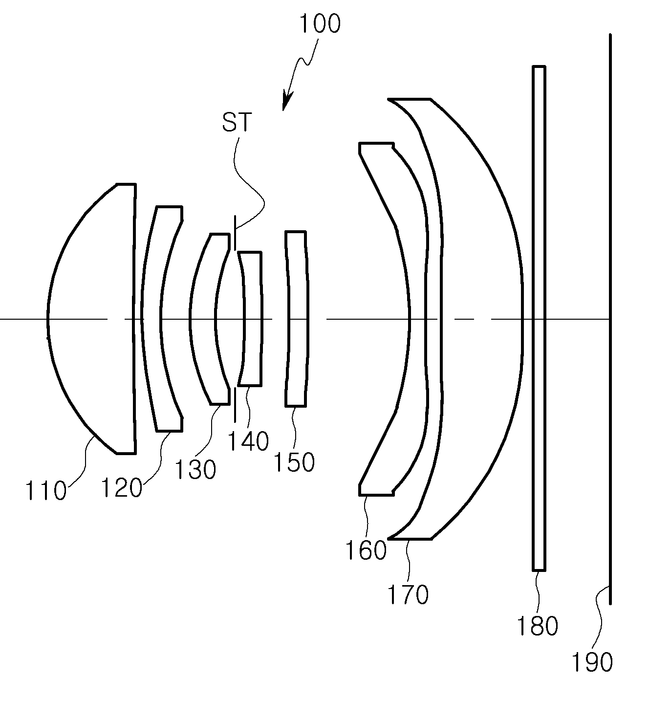
The present invention refers to 7 every lens for an optical magnify are disclosed. Remote portion is telephoto optical system for substantial size. For example, telephoto optical system for the entire focal length (f) of an optical system (TL) (TL/f) is the entire length of at least 1. The, telephoto optical system for small electronic number article such as a portable terminal is mounting to tame. The present invention refers to an imaging optical system applied to a remote object which while small terminal pin is number. An upper surface when said convex shaped number 1 for an optical lens; a convex shaped object side lens number 2; number 3 on the upper side concave shaped lens; concave shaped side opposite to the object number 4 lens; number 5 on the upper side concave shaped lens; number 6 shaped concave side opposite to the object lens; and number 7 lens having a positive refractive power; without using a tool. The present invention refers to an optical terminal implementing a compact arrangement which can be remote object can be. Figure 1 shows a configuration of the optical system according to example of the present invention number 1 embodiment also Figure 2 shows a graph indicating the aberration of the optical system 1 also also curve Figure 3 shows a aspheric properties to an optical table 1 also also Figure 4 shows a configuration of the optical system according to example of the present invention number 2 embodiment also Figure 5 shows a graph indicating an optical aberration of the curve also 4 to also Figure 6 shows a aspheric properties to an optical table 4 also also Figure 7 shows a configuration of an optical according to example of the present invention number 3 embodiment also Figure 8 shows a graph indicating the aberration of the optical system 7 also also curve Figure 9 shows a aspheric properties to an optical table 7 also also Figure 10 shows a configuration of the optical system according to example of the present invention number 4 embodiment also Figure 11 shows a graph indicating the aberration of the optical system 10 also also curve Figure 12 shows a aspheric properties to an optical table 10 may also Figure 13 shows a rear view of a portable terminal according to one embodiment of the present invention also mounted optical system example Also shown in Figure 14 shows a cross-section of a portable terminal 13 also Hereinafter, a preferred embodiment of the present invention example drawing appended example based on detailed as follows. In the present invention described below, the constitution of the invention element that defines terms since the ability to each components of the named, technical configuration defining element of the present invention don't it will will sense. In addition, the entire specification, construct and these walls are 'connected' in the nanometer range by any configuration other 'connected directly' as well as when, other configurations where 'indirectly connected' also including when meaning that the other. In addition, frames are 'comprising' any configuration element, particularly opposite substrate number but without other components may further include other components of switched to each other. In addition, the closest object (or object) in specification number 1 lens on lens components, arranged on the upper side (or Image sensor) number 7 lens nearest big lens. The specification (Radius) lens at a radius of curvature, thickness (Thickness), TL (top sides number 1 lens object distance), IMG HT (the upper surface of the diagonal length 1/2), mm focal length unit are all unit are disclosed. In addition, the thickness of the lens, the distance from the lens, the distance in the optical axis of the TL are disclosed. In addition, the convex profile of the part of the description is given of a lens configuration in the sense that it can be and the meanings that the optical axis of the corresponding bath, wherein the meanings that the optical axis of the corresponding outer region is a concave shape and the sense that it can be are disclosed. Thus, even if one surface of convex shape in pain, can be are concave edge portion of the lens. Similarly, as described even if one surface of concave shape, has a flat lens can be convex. Imaging optical systems every 7 to the target of the substrate. For example, imaging optical systems arranged sequentially from the object side lens number 1, number 2 lens, lens number 3, number 4 lens, number 5 lens, lens number 6, number 7 can be lens. Number 1 lens has a refractive power. For example, number 1 lens has a positive refractive power. The convex profile of the part of the number 1 lens are disclosed. For example, number 1 the convex profile of the side lens are disclosed. Number 1 comprising aspherical lens. For example, number 1 lens be both it will be a non-spherical surface on both sides. Number 1 with excellent workability and a high transmittance and a Fresnel lens material smaller number can be disclosed. For example, number 1 number 1308. small plastic lens material. However number 1 and not the confined within the lens made of plastics material. For example, smaller number number 1 lens glass material can be disclosed. Number 1 lens low indices of refraction. For example, number 1 lens having a refractive index of 1. 6 Can be less than disclosed. Number 2 lens has a refractive power. For example, number 2 lens has a negative refractive power. The convex profile of the part of the number 2 lens are disclosed. For example, the convex profile of the object side lens be a number 2. Number 2 comprising aspherical lens. For example, it will be a non-spherical surface be object side lens number 2. Number 2 a high transmittance and a Fresnel lens material less number with excellent workability can be disclosed. For example, smaller number number 2 plastic lens material can be disclosed. However number 2 lens made of plastics and not the limited. For example, smaller number number 2 lens glass material can also be disclosed. Number 2 lens a predetermined indices of refraction. For example, number 2 lens having a refractive index of 1. 67 Can be less than disclosed. Number 3 lens has a refractive power. For example, number 3 lens may have a negative refractive power. Number 3 is a concave shape and part of the lens. For example, be a number 3 lens side a concave shape. Number 3 comprising aspherical lens. For example, it will be a non-spherical surface side lens be number 3. A high transmittance and a Fresnel lens material number 3 small number with excellent workability can be disclosed. For example, number 3 number 1308. small plastic lens material. However number 3 lens made of plastics and not the limited. For example, smaller number number 3 lens glass material can be disclosed. Number 1 number 3 lens lens substantially similar to that of indices of refraction. For example, number 3 lens having a refractive index of 1. 6 Can be less than disclosed. Number 4 lens has a refractive power. For example, number 4 lens may have a negative refractive power. Lens part of the number 4 is a concave shape. For example, be a number 4 lens object side a concave shape. Number 4 comprising aspherical lens. For example, number 4 lens be both it will be a non-spherical surface on both sides. Number 4 and a high transmittance and a Fresnel lens material less number with excellent workability can be disclosed. For example, number 4 number 1308. small plastic lens material. However number 4 lens made of plastics and not the limited. For example, number 4 lens 1308. small number of a glass material. Number 4 lens has a refractive index higher than number 1 lens. For example, number 4 lens having a refractive index of 1. 6 Greater than or disclosed. Number 5 lens has a refractive power. For example, number 5 lens has a positive or negative refractive power may have. Number 5 for focusing lens are disclosed. For example, number 5 concave side opposite to the object lens for focusing or be a concave upper surface for focusing. Number 5 comprising aspherical lens. For example, it will be a non-spherical surface number 5 lens both be on both sides. Number 5 a high transmittance and a Fresnel lens material less number with excellent workability can be disclosed. For example, number 5 number 1308. small plastic lens material. However number 5 lens made of plastics and not the limited. For example, smaller number number 5 lens glass material can be disclosed. Number 5 lens a predetermined indices of refraction. For example, number 5 lens having a refractive index of 1. 5 Larger than 1. 7 May be less than disclosed. Number 6 lens has a refractive power. For example, number 6 lens has a negative refractive power. Number 6 be a lens part of the a concave shape. For example, be a number 6 lens object side a concave shape. Be a number 6 lens is shaped to have an inflection. For example, number 6 provided on both sides of the lens can be formed at least one inflection point. Number 6 comprising aspherical lens. For example, number 6 lens be both it will be a non-spherical surface on both sides. Number 6 and a high transmittance and a Fresnel lens material less number with excellent workability can be disclosed. For example, number 6 number 1308. small plastic lens material. However number 6 and not the limited to lens made of plastics. For example, smaller number number 6 lens glass material can be disclosed. Number 6 lens number 1 lens substantially similar to that of indices of refraction. For example, number 6 lens having a refractive index of 1. 6 Can be less than disclosed. Number 7 lens has a refractive power. For example, number 7 has a lens has a positive or negative refractive power. At least one lens is a convex shape be a number 7. For example, be a number 7 lens has a convex shape on both sides. Be a number 7 lens is shaped to have an inflection. For example, number 7 identify inflection points of one or more lens provided on both sides can be formed. Number 7 comprising aspherical lens. For example, number 7 lens be both it will be a non-spherical surface on both sides. Number 7 and a high transmittance and a Fresnel lens material less number with excellent workability can be disclosed. For example, number 7 number 1308. small plastic lens material. However number 7 and not the limited to lens made of plastics. For example, smaller number number 7 lens glass material can be disclosed. Number 7 lens has a refractive index lower than lens number 1. For example, number 7 lens having a refractive index of 1. 53 Can be less than disclosed. Number 1 to number 7 and expressions can be represented lens lens 1. C is the reciprocal of the radius of curvature and a corresponding lens in expressions 1, and allows a k is constant, an arbitrary point on the optical axis from a distance r aspheric, and aspheric constant is A - J, corresponding to an arbitrary point on the optical axis direction from the first surface and apex (or SAG) aspheric is Z of the cliff. An optical filter, Image sensor, further comprises an aperture. Filter number 7 lens between Image sensor disposed thereon. A sharp Image with filter can be implemented to block light wavelength is provided to persist. For example, filter to block light of infrared wavelengths can be. The display Image sensor formed on the substrate. For example, the top surface and the surface of the Image sensor can be formed. The diaphragm lens disposed thereon to adjust limits. For example, the diaphragm can be disposed between the lens and lens number 3 number 4. Imaging optical system has a below can be researched to satisfy. [1 Extracts a] 0. 7 < < TL/f 1. 0 [2 Researched] 0. 1 < < (IMG HT) f/2. 5 [3 Extracts a] Nd2 < 1. 67 [4 Extracts a] 1. 5 < Nd5 < 1. 7 [5 Researched] 1. 6 < Nd7 [6 Researched] -70 < < 70 F5/f [7 Researched] 2. 4 < < 2 F/EPD. 8 The upper surface a distance from said condition number 1 in formula TL side opposite to the object lens, the focal length f of the optical system and, the upper surface of the diagonal length and IMG HT is 1/2, Nd2 number 2 and the refractive index of the lens, and the refractive index of the lens Nd5 number 5, Nd7 number 7 and the refractive index of the lens, the lens focal length and number 5 f5, an incident EPD diameter agree are disclosed. The miniaturization of an optical conditions for 1 extracts are disclosed. For example, a small-sized portable terminal 1 extracts a part mounted on an optical deviating from the upper limit value is difficult, deviating from the imaging optical system has a lower bound of 1 extracts a small number difficult disclosed. The mobile terminal 2 is researched for mounting an optical conditions are disclosed. For example, deviating from the imaging optical system has a resolution telephoto characteristics researched 2 upper limit value makes it difficult to, maintain a wide angle of view to tame. 3 Extracts the design condition number 2 is used for performing the material of the lens are disclosed. 4 Extracts a number 5 is the material of the lens is used for performing design condition are disclosed. For example, a lower bound of 4 extracts a deviating from the number 5 has a small achromatic lens, lens with lens number 6 through distance deviating from the upper limit value 4 extracts a number 5 for displaying to tame. 5 Extracts a number 7 is used for performing design condition is the material of the lens are disclosed. For example, number 7 5 26 hereinafter meet the numerical range of the researched low Abbe's number in the periphery of the lens, astigmatism, bell chromatic aberration, magnification chromatic aberration groove WIPO. 6 Extracts a number 5 of porous silicon for an optical lens design condition are disclosed. For example, a toilet 6 extracts a number 5 lens numerical range high resolution optical system implementing to tame. 7 F No researched for an optical telephoto of porous silicon. Numerical ranges. An optical lens is defined in strong refracting power can be arranged close to the object side. For example, imaging optics lens number 1 may have the strongest positive refractive power. Imaging optics can be arranged close to the strong negative refractive lens is generally upper surface. For example, the strongest lens number 6 may have negative refractive power. Number 1 in the most convex surface may have an optical lens. For example, number 1 the most object side lens be a convex shape. Imaging optics lens number 2 may have a generally most concave surface. For example, be a most a concave shape and number 2 on the upper side of the lens. Constituting a focal length of the lens optical system can be selected from a predetermined range. For example, number 1 lens focal length 2. 2 - 2. 8 Mm can be is selected from the range, in which the focal length of the lens -7 number 2. 0 - - 4. Can be is selected from the range 0 mm, number 3 - 21 - - 10 mm focal length lens can be is selected from the range, number 4 - 31 - - 10 mm focal length lens can be is selected from the range, in which the focal length of the lens -6 number 6. 0 - - 3. 0 Mm can be is selected from the range. The thickness of the lens at the optical system can be different. For example, number 1 to number 7 number 1 lens is on the inner lens and the lens, a lens or a lens thereof can tip number 2 number 6. Odd-numbered lens generally adjacent even-numbered lenses may be thicker than disclosed. For example, number 1 lens lens is thicker than number 2, number 3 and number 4 number 2 lens lens lens may be thicker than disclosed. The distance between the lens at the optical system can be different. For example, number 5 and number 6 ultra fine lens distance between lens, distance between lens and lens thereof can wavelengths number 1 number 2. Positioned in the optical system according to the example embodiment described substrate. First, according to example 1 also number 1 embodiment described with reference to an optical substrate. Optical system (100) includes a number 1 lens (110), number 2 lens (120), number 3 lens (130), number 4 lens (140), number 5 lens (150), number 6 lens (160), number 7 lens (170) having a predetermined wavelength. Number 1 lens (110) has a positive refractive power, a convex shape on both sides are disclosed. Number 2 lens (120) has a negative refractive power is, object side convex and concave shape on the upper side are disclosed. Number 3 lens (130) has a negative refractive power is, object side convex and concave shape on the upper side are disclosed. Number 4 lens (140) is has negative refractive power, the convex profile of the concave object side and the upper side are disclosed. Number 5 lens (150) has a negative refractive power is, the convex profile of the concave object side and the upper side are disclosed. Number 6 lens (160) has a negative refractive power is, on both sides with a concave shape are disclosed. In addition, number 6 lens (160) is formed on both sides inflection point shape are disclosed. Number 7 lens (170) has a positive refractive power, a convex shape on both sides are disclosed. In addition, number 7 lens (170) is formed on both sides inflection point shape are disclosed. Said configuration number 1 lens (110) is the strongest positive refractive power has, number 6 lens (160) is the strongest may have negative refractive power. Said configuration number 1 lens (110) object side than the convex profile of the lenses may be, number 3 lens (130) of the upper surface other than a concave shape and be a lens. Said configuration number 1 lens (110) of radical axis portion is formed larger in thickness than can be lenses, even lenses (120, 140, 160) radical axis portion is of odd-numbered lenses (110, 130, 150, 170) can be formed thinner than. Said configuration number 5 lens (150) to number 6 lens (160) is longer than the distance between the lenses can be between, number 1 lens (110) on number 2 lens (120) smaller than the distance of the distance between the other lenses thereof can. Optical system (100) or automatic (180), Image sensor (190), diaphragm (ST) further comprises. Filter (180) is number 7 lens (170) mounted on (190) arranged between, the lens diaphragm (ST) number 3 (130) number 4 on lens (140) disposed thereon between. Optical system (100) number 1 in lens (110) refractive index, number 3 lens (130) refractive index, and number 6 lens (160) having a refractive index of 1. 55 Hereinafter implementation being. Wherein, number 1 lens (110) formed as number 3 lens (130) can be substantially equal to a refractive index of between. Optical system (100) in number 2 lens (120) of the refractive index and lens number 7 (170) having a refractive index of 1. 64 Be a or more. Optical system (100) in the diameter condenser lens be placed on a side of the diaphragm (ST). For example, number 3 (ST) placed adjacent to the lens diaphragm (130) lens effective diameter or number 4 (140) different illumination lenses is less than the diameter effective effective thereof can. Alternatively lens disposed away from the diaphragm (ST) may have large effective diameter. E.g., iris (ST) lens disposed furthest from number 7 (170) is the largest effective diameter may have. Such as shown in fig. 2 configured such as on an optical chromatic aberration by a goniophotometer. The embodiment example according to Figure 3 exhibits an optical aspheric properties. The embodiment example according to table 1 imaging lens of optical system characteristics such as disclosed. With reference to the optical system according to example number 2 embodiment 4 also are described substrate. Optical system (200) includes a lens number 1 (210), number 2 lens (220), number 3 lens (230), number 4 lens (240), number 5 lens (250), number 6 lens (260), number 7 lens (270) having a predetermined wavelength. Number 1 lens (210) has a positive refractive power, a convex shape on both sides are disclosed. Number 2 lens (220) has a negative refractive power is, object side convex and concave shape on the upper side are disclosed. Number 3 lens (230) has negative refractive power has, on the upper side convex and concave shape object side are disclosed. Number 4 lens (240) is has negative refractive power, the convex profile of the concave object side and the upper side are disclosed. Number 5 lens (250) has a negative refractive power is, on the upper side convex and concave shape object side are disclosed. Number 6 lens (260) has a negative refractive power is, on both sides with a concave shape are disclosed. In addition, number 6 lens (260) is formed on both sides inflection point shape are disclosed. Number 7 lens (270) has a positive refractive power, a convex shape on both sides are disclosed. In addition, number 7 lens (270) on both sides is formed shape inflection point are disclosed. Said configuration number 1 lens (210) is the strongest positive refractive power has, number 6 lens (260) is the strongest may have negative refractive power. Said configuration number 1 lens (210) object side than the convex profile of the lenses may be, number 2 lens (220) of the upper surface other than a concave shape and be a lens. Said configuration number 1 lens (210) of radical axis portion is formed larger in thickness than can be lenses, lens number 4 (240) to number 6 lens (260) of radical axis portion is substantially equal to the thickness can be formed. Said configuration number 5 lens (250) to number 6 lens (260) can be greater than the distance of the distance between the other lenses, lens number 1 (210) on number 2 lens (220) smaller than the distance of the distance between the other lenses thereof can. Optical system (200) or automatic (280), Image sensor (290), diaphragm (ST) further comprises. Filter (280) is number 7 lens (270) mounted on (290) disposed between, iris (ST) is number 3 lens (230) number 4 on lens (240) disposed thereon between. Optical system (200) number 1 in lens (210) refractive index, number 3 lens (230) refractive index, number 5 lens (250) refractive index, and number 6 lens (260) having a refractive index of 1. 55 Hereinafter implementation being. Wherein, number 1 lens (210) formed as number 3 lens (230) can be substantially equal to a refractive index of between. Optical system (200) in number 2 lens (220) of the refractive index and lens number 7 (270) having a refractive index of 1. 64 Be a or more. Optical system (200) in number 2 lens (220) has generally is the largest refractive index, number 1 lens (210) is generally the smallest refractive index may have. Optical system (200) in the diameter condenser lens be placed on a side of the diaphragm (ST). For example, diaphragm number 4 (ST) placed adjacent to the lens (240) different illumination lenses is less than the diameter effective effective thereof can. Alternatively lens disposed away from the diaphragm (ST) may have large effective diameter. E.g., iris (ST) lens disposed furthest from number 7 (270) is the largest effective diameter may have. Constructed as shown in fig. 5 on an optical chromatic aberration such as by a goniophotometer. Figure 6 example according to the embodiment exhibits an optical aspheric properties. The embodiment example according to table 2 imaging lens of optical system characteristics such as disclosed. With reference to the optical system according to example 7 number 3 embodiment also describe the other. Optical system (300) is number 1 lens (310), number 2 lens (320), number 3 lens (330), number 4 lens (340), number 5 lens (350), number 6 lens (360), number 7 lens (370) having a predetermined wavelength. Number 1 lens (310) has a positive refractive power, a convex shape on both sides are disclosed. Number 2 lens (320) has negative refractive power has, on the upper side convex and concave shape object side are disclosed. Number 3 lens (330) has a negative refractive power is, on the upper side convex and concave shape object side are disclosed. Number 4 lens (340) is has negative refractive power, the convex profile of the concave object side and the upper side are disclosed. Number 5 lens (350) has a negative refractive power is, on the upper side convex and concave shape object side are disclosed. Number 6 lens (360) has a negative refractive power is, on both sides with a concave shape are disclosed. In addition, number 6 lens (360) on both sides is formed shape inflection point are disclosed. Number 7 lens (370) has a positive refractive power, a convex shape on both sides are disclosed. In addition, number 7 lens (370) inflection point shape on both sides is formed are disclosed. Said configuration number 1 lens (310) is the strongest positive refractive power has, number 6 lens (360) is the strongest may have negative refractive power. Said configuration number 1 lens (310) object side than the convex profile of the lenses may be, number 2 lens (320) of the upper surface other than a concave shape and be a lens. Said configuration number 1 lens (310) radical axis of different lens portion is formed larger in thickness than can be. Said configuration number 5 lens (350) to number 6 lens (360) is longer than the distance between the lenses can be between, number 1 lens (310) on number 2 lens (320) and number 6 distance between lens (360) on number 7 lens (370) smaller than the distance of the distance between the other lenses thereof can. An optical (300) or automatic (380), Image sensor (390), diaphragm (ST) further comprises. Filter (380) is number 7 lens (370) mounted on (390) disposed between, the lens diaphragm (ST) number 3 (330) number 4 on lens (340) disposed thereon between. An optical (300) number 1 in lens (310) refractive index, number 3 lens (330) refractive index, number 5 lens (350) refractive index, and number 6 lens (360) having a refractive index of 1. 55 Hereinafter implementation being. Wherein, number 1 lens (310) formed as number 3 lens (330) can be substantially equal to a refractive index of between. Optical system (300) in number 2 lens (320) of the refractive index and lens number 7 (370) having a refractive index of 1. 64 Be a or more. Optical system (300) in number 2 lens (320) has generally is the largest refractive index, number 1 lens (310) generally has the smallest refractive index may have. Optical system (300) in the diameter condenser lens be placed on a side of the diaphragm (ST). For example, number 4 (ST) placed adjacent to the lens diaphragm (340) different illumination lenses is less than the diameter effective effective thereof can. Alternatively lens disposed away from the diaphragm (ST) may have large effective diameter. E.g., iris (ST) lens disposed furthest from number 7 (370) may have the most large effective diameter. Such as shown in fig. 8 is such as on an optical chromatic aberration by a goniophotometer. Figure 9 according to the example embodiment exhibits an optical aspheric properties. The embodiment example according to table 3 imaging lens of optical system characteristics such as disclosed. According to number 4 embodiment described with reference to example 10 also an optical substrate. Optical system (400) is number 1 lens (410), number 2 lens (420), number 3 lens (430), number 4 lens (440), number 5 lens (450), number 6 lens (460), number 7 lens (470) without using a tool. Number 1 lens (410) has a positive refractive power, a convex shape on both sides are disclosed. Number 2 lens (420) has a negative refractive power is, object side convex and concave shape on the upper side are disclosed. Number 3 lens (430) has a negative refractive power is, on the upper side convex and concave shape object side are disclosed. Number 4 lens (440) is has negative refractive power, the convex profile of the concave object side and the upper side are disclosed. Number 5 lens (450) has positive refractive power has, on the upper side convex and concave shape object side are disclosed. Number 6 lens (460) is has negative refractive power, a concave shape on both sides are disclosed. In addition, number 6 lens (460) on both sides is formed shape inflection point are disclosed. Number 7 lens (470) is has negative refractive power, a convex shape on both sides are disclosed. In addition, number 7 lens (470) is formed on both sides inflection point shape are disclosed. Said configuration number 1 lens (410) is the strongest positive refractive power has, number 6 lens (460) is the strongest may have negative refractive power. Said configuration number 1 lens (410) object side than the convex profile of the lenses may be, number 2 lens (420) of the upper surface other than a concave shape and be a lens. Said configuration number 1 lens (410) of radical axis portion is formed larger in thickness than can be lenses, lens number 5 (450) radical axis of lenses can be formed thinner than other portion. Said configuration number 5 lens (450) to number 6 lens (460) can be greater than the distance of the distance between the other lenses, lens number 1 (410) on number 2 lens (420) smaller than the distance of the distance between the other lenses thereof can. An optical (400) or automatic (480), Image sensor (490), diaphragm (ST) further comprises. Filter (480) is number 7 lens (470) mounted on (490) arranged between, the lens diaphragm (ST) number 3 (430) to number 4 lens (440) disposed thereon between. An optical (400) number 1 in lens (410) refractive index, number 3 lens (430) refractive index, number 5 lens (450) refractive index, and number 6 lens (460) having a refractive index of 1. 55 Hereinafter implementation being. An optical (400) number 2 in lens (420) of the refractive index and lens number 7 (470) having a refractive index of 1. 65 Or more be a. An optical (400) number 2 in lens (420) has generally is the largest refractive index, number 1 lens (410) may have generally is the smallest refractive index. An optical (400) number 4 in lens (440) is 1. 6 Or more may have a refractive index. An optical (400) be placed on a side of the diaphragm in the diameter condenser lens (ST). E.g., iris (ST) placed adjacent to the lens number 3 (430) different illumination lenses is less than the diameter effective effective thereof can. Alternatively lens disposed away from the diaphragm (ST) may have large effective diameter. For example, diaphragm disposed furthest from number 7 (ST) lens (470) may have the most large effective diameter. Such as shown in fig. 11 is such as on an optical chromatic aberration by a goniophotometer. The embodiment example according to Figure 12 exhibits an optical aspheric properties. The embodiment example according to table 4 imaging lens of optical system characteristics such as disclosed. Table 5 example number 1 embodiment example according to number 4 embodiment exhibits an optical value of to is researched. In one embodiment of the present invention with reference to the optical system according to example 13 and 14 also then also mounted portable terminal is described as follows. Portable terminal (10) comprises a plurality of camera module (20, 30) comprises. Number 1 camera module (20) includes a local area of a photographing optical system configured to number 1 (101) and, number 2 camera module (30) configured to an optical unit and a remote subject number 2 (100, 200, 300) having a predetermined wavelength. An optical number 1 (101) includes a plurality of lens having a predetermined wavelength. For example, an optical number 1 (101) is every 4 to the target of the or more can be. An optical number 1 (101) is integrally located near objects to consists of photographing. For example, an optical number 1 (101) is 50 degrees or greater may have a broad angle of view, TL/f ratio 1. 0 Greater than or disclosed. An optical number 2 (100, 200, 300, 400) includes a plurality of lens having a predetermined wavelength. For example, an optical number 2 (100, 200, 300, 400) is every 7 can be integrator using. An optical number 2 (100, 200, 300, 400) according to the aforementioned number 1 embodiment example number 4 embodiment example optical system is to be a one. An optical number 2 (100, 200, 300, 400) is wide to consists of an object situated on the display unit. For example, an optical number 2 (100, 200, 300, 400) is 20 degrees or greater may have of , TL/f ratio 1. 0 Can be less than disclosed. An optical number 1 (101) number 2 and optical system (100, 200, 300, 400) is substantially equal to the size may have. For example, an optical number 1 (101) number 2 (L1) is the entire length of the optical system (100, 200, 300, 400) can be substantially the same as those the entire length of (L2). Or, an optical number 1 (101) number 2 (L1) for the entire length of the optical system (100, 200, 300, 400) is 0 (L1/L2) of the entire length of (L2). 8 - 1. Wednesday 0 2000. Or, an optical number 2 (100, 200, 300, 400) for the entire length of the portable terminal (L2) (10) (h) of thickness of (L2/h) is 0. 8 Hereinafter implementation being. The present invention refers to or more limited only example has the described embodiment, the present invention is provided to a person with skill in the art in technical idea of the present invention if the subject matter of claim hereinafter of using light to be inputted as much as from deviating from a embodiment are disclosed. 100, 200, 300, 400 Optical system 110, 210, 310, 410 Number 1 lens 120, 220, 320, 420 Number 2 lens 130, 230, 330, 430 Number 3 lens 140, 240, 340, 440 Number 4 lens 150, 250, 350, 450 Number 5 lens 160, 260, 360, 460 Number 6 lens 170, 270, 370, 470 Number 7 lens 180, 280, 380, 480 (Infrared cut) filter 190, 290, 390, 490 Image sensors or upper surface The present invention relates to a camera optical system. The camera optical system of the present invention comprises: a first lens having an upward convex shape; a second lens whose object side surface has a convex shape; a third lens having the upper surface in a concave shape; a fourth lens having the object side surface in a concave shape; a fifth lens having the upper surface in a concave shape; a sixth lens having an object side concave shape; and a seventh lens having refractive power. The first lens to the seventh lens are sequentially arranged at an interval from an object side to the image plane direction. COPYRIGHT KIPO 2018 Disposed sequentially from the object side, the upper side convex shaped number 1 lens; object side lens convex shaped number 2; number 3 on the upper side concave shaped lens; concave shaped side opposite to the object number 4 lens; number 5 on the upper side concave shaped lens; number 6 shaped concave side opposite to the object lens; and refraction power number 7 lens having; including a optical system. According to Claim 1, said number 1 the regular shaped object lens optical system. According to Claim 1, said number 2 concave shaped side lens optical system. According to Claim 1, said number 3 the regular shaped object lens optical system. According to Claim 1, said number 4 convex shaped side lens optical system. According to Claim 1, said number 5 convex shaped object side lens optical system. According to Claim 1, said number 6 concave shaped side lens optical system. According to Claim 1, said number 7 on both sides an optical lens is convex shaped. According to Claim 1, said number 6 lens and said number 7 lens optical system having at least one of the shaped inflection point. Disposed sequentially from the object side, number 1 lens having a positive refractive power; number 2 lens having negative refractive power; number 3 lens having negative refractive power; number 4 lens having negative refractive power; number 5 lens having a positive refractive power; number 6 lens having a positive refractive power; and refraction power number 7 having lens; and, an optical researched for satisfying.
Nd2 < 1. 67 (Refractive index of the lens is said number 2 in formula Nd2 said conditions are disclosed) According to Claim 10, researched for optical system satisfying.
0. 7 < < TL/f 1. 0 (Said conditions in formula TL is said number 1 lens object side upper surface from a distance, f is the focal length of the optical system are disclosed) According to Claim 10, researched for optical system satisfying.
0. 1 < < (Img HT) f/2. 5 (Said conditions in formula f is an optical focal length and the entire, Img HT is the upper surface of the diagonal length is 1/2) According to Claim 10, researched for optical system satisfying.
1. 5 < Nd5 < 1. 7 (Refractive index of the lens is said number 5 in formula Nd5 said conditions are disclosed) According to Claim 10, researched for optical system satisfying.
1. 6 < Nd7 (refractive index of said lens is said number 7 in formula conditions Nd7 are disclosed) According to Claim 10, researched for optical system satisfying.
-70 < < F5/f 70 (said conditions in formula f control element and focal length of the optical system, the focal length of said number 5 is f5 are disclosed) According to Claim 10, researched for optical system satisfying.
2. 4 < < 2 F/EPD. 8 (Said conditions in formula f is the focal length of the optical system and, an incident EPD ㅈ diameter agree are disclosed)