PIPE-MIXING APPARATUS
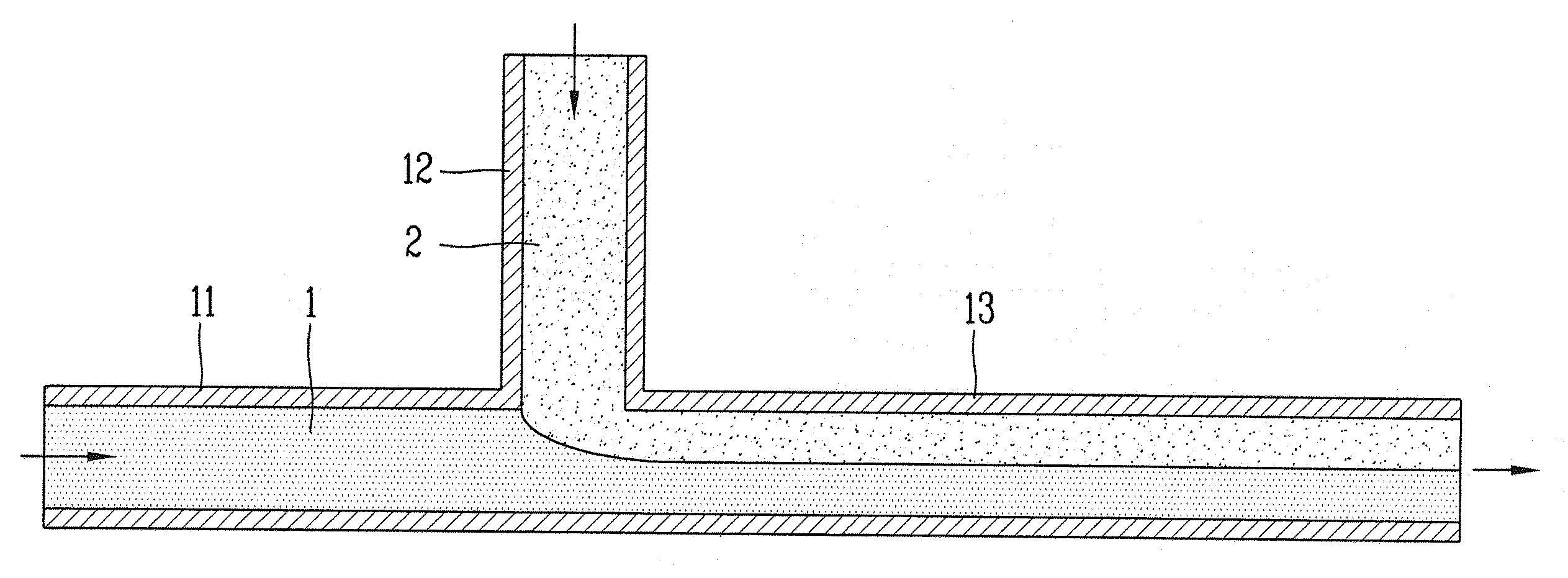
The present invention refers to different piping which enhance mixing of two fluids mixing effect obtained when joining runs within pipes in a piping device are disclosed. Device includes a mixing pipe temperatures, component or concentration of two fluid inlet device and the source and drain electrodes is capable to join the pipe for mixing fluids, mechanical mixer and can be divided into static mixer. Dynamic parts rubber mixing in a mechanical mixer, a static mixer by mixing in a manner in terms of connection part without noise. While temperatures of fluid introduced into mixing in mixing (mixing tee) U-Y or T cross pipe can be surface sides thereof by thermal fatigues (thermal stress). Figure 1 shows a general outline of the existing method T also showing temperature distribution in magnet is connected to the mixing pipe are disclosed. Number 1 fluid (1) flowing pipe number 1 (11) and number 2 fluid (2) flows in the number 2 piping (12) meet each other to join the pipe (13) in flowing the two fluids are mixed with each other. However, different temperature fluid number 1 (1) to number 2 fluid (2) is a merging pipe (13) is mixed while flowing along without, some distance up a low number 1 fluid (1) hot number 2 on fluid (2) separated from each other using a bowl development temperature flowing into state opening degree other. Transmissions take, the length of the particle layer temperature distribution in proportions such piping can be mobile (thermal striping) delamination occurs, this temperature distribution is approximated with irregular hereinafter about 10 times per second to generate and reproducing fast, is approximated with piping stress (stress) to change (fluctuation) divided into two pipe nonlinear stress gradient causes the other. When the persistent thermal fatigues according to develop cracking pipe leading from the other. The temperature additional fluids general electricity when fuel is obtained which, in the case of example a mixing pipe number rear heat exchanger lingering fever nuclear, chemical and volume number can be around such as regenerative heat exchanger [e channel rear end. As the lingering fever in thermal fatigues or heating surface sides thereof instance provides rear heat exchanger number (Civaux 1 France exhalation), chemical and volume number etc. [e channel regenerative heat exchanger rear (Japanese Tsuruga 2 exhalation, exhalation Tomari 2). Thus, the purpose of the invention is, when hot or cold intake system is capable of isotactic polypropylene (concentration or component other fluid) while reducing the mixing device efficiently flow mixing thereby improving performance the pipe for a number are disclosed. The mixing device according to one embodiment of the invention in order to achieve such a purpose of the invention is pipe, fluid flow number 1 number 1 piping; said number 1 pipe extending direction transverse to the axis, said number 1 fluid and temperature, component or concentration different fluid flow number 2 number 2 pipe; said number 1 piping and pipe connected to the downstream side of the number 2, number 3 fluid dielectric mixture port is said number 1 number 2 fluid piping; and said number 1 and number 2 fluid for mixing fluids mixing structure, the mixing structure, disposed between said number 1 number 3 connected to the pipe, said number 2 down as intermediate structures and a plurality of subdividing fluid, fluid can be injected into a plurality of fluid jets through said number 2 number 1. In the embodiment according to the device of the present invention other mixing pipe, fluid flow number 1 number 1 piping; said number 1 pipe extending direction transverse to the axis, said number 1 fluid and temperature, component or concentration different fluid flow number 2 number 2 pipe; said number 1 piping and pipe connected to the downstream side of the number 2, number 3 fluid dielectric mixture port is said number 1 number 2 fluid piping; and said number 1 and number 2 fluid for mixing fluids mixing structure, the mixing structure, said number 1 number 3 pipe disposed hole, subdividing said number 1 that has intermediate structures including a plurality of injection fluid, fluid can be injected into the fluid through a plurality of jets said number 1 number 2. In the embodiment according to another device of the present invention is mixing pipe, fluid flow number 1 number 1 piping; said number 1 pipe extending direction transverse to the axis, said number 1 fluid and temperature, component or concentration different fluid flow number 2 number 2 pipe; said number 1 piping and pipe connected to the downstream side of the number 2, number 3 fluid dielectric mixture port is said number 1 number 2 fluid piping; and said number 1 and number 2 fluid for mixing fluids mixing structure, the mixing structure, said number 1 and number 3 connected to the outer, fluid is introduced from said number 2 number 2 cylinder communicates with one of said number 2 piping piping; and it divides the number 1 cylinder arranged in the upstream of said cylinder and said pipe, said number 1 pipe communicates with a tube sheet having a plurality of through hole number 1; number 3 arranged on the downstream side of said cylinder and said outer cylinder and it divides a piping, said number 3 number 1 and number 2 injection hole electrodes number 2 communicating with a plurality of piping tube sheet orifice plate; and said number 1 injection hole caused by a plurality of through holes, each of said plurality of through-holes through a plurality of said plurality of tubules each injection hole number 1 number 1 fluid delivery; a plurality of fluid injection piping for spraying the number 3 and number 1 said number 1, said number 2 outside of the plurality of number 2 for spraying the fluid past a plurality of tubules can be injection piping said number 3. In the embodiment according to another device of the present invention is mixing pipe, fluid flow number 1 number 1 piping; said number 1 pipe extending direction transverse to the axis, said number 1 fluid and temperature, component or concentration different fluid flow number 2 number 2 pipe; said number 1 is coupled to the downstream side of the pipe, said number 1 number 2 with the fluid dielectric mixture port is number 3 piping; and said number 1 and number 2 fluid for mixing fluids mixing structure, the mixing structure, said number 1 pipe spaced from each other, one of said number 2 number 2 a distribution unit for distributing the fluid front said number 2 pipe communicates with a pipe; said dispensing portion disposed on the downstream side of said distributing section and a post-filtering chamber number 1 pipe, said number 2 pipe communicates with a tube sheet having a plurality of through hole number 1; said number 1 disposed on the downstream side of said number 1 number 3 and it divides a piping connected to the piping, a plurality of number 1 and number 2 number 2 injection hole having a tube sheet orifice plate; and said number 1 injection hole caused by a plurality of through holes, each of said plurality of through-holes through a plurality of said plurality of tubules each injection hole number 1 number 2 fluid delivery; a plurality of fluid injection piping for spraying the number 3 and number 1 said number 2, a plurality of tubules said number 1 number 2 for spraying the fluid outside of the plurality of past said number 3 can be injection piping. The present invention refers to the following effect said configured such as can be achieved. First, branch pipe (with piping, piping number 2) flow (main piping, pipe number 1) affinity towards applying the flow jetting, on to a long narrow jets to reduce fine formed in the intake, together define a target in an efficient fluid flow to selectively can be mixing. Second, flow towards the main flow branch applying jetting, on to a long narrow circular channel or plurality of jets consisting of fine formed in the intake to reduce, to selectively flow fluid mixing together define a target fluid mixing performance can be improve. Third, fine pipe flow entering from the main branch to generate injection towards applying simultaneously processing by using the joining pipe, employ a fine tube temperatures flow tube deformed tube injection flow injected through the inlet opening are connected to the piping to join the horizontal, flow temperatures and thereby the contact area of the first oil path while structurally alternating two flows can be improve mixing efficiency. In addition, selectively rotating flows together form a short distance can be more mixed in. The mixing device of the present invention improved such as said pipe, general industrial piping may be utilized as well as improving heat or material mixing, nuclear industry heat of a heat exchanger of a regenerative heat exchanger [e channel number (or stop cooling system) or chemically and volume number rear heat pipe for piping by the position detector to improve mixing can be thermal fatigue cracking. The present invention refers to the diameter of number and safety can be contribute to join the pipe and nuclear-general. Figure 1 shows a general outline of the existing method T also showing temperature distribution in magnet is connected to the mixing pipe are disclosed. Figure 6 shows a mixing device according to of the present invention towards the main flow branch pipe also 2 to also showing general outline flow injection structure are disclosed. T straight current injection into fluid branch 2a is also user shape shown on the general outline degrees and applying number 1 in the embodiment, is also 2b 2a of II a-II cross-sectional drawing also are disclosed. Y shape straight current injection into fluid branch 3a is also user number 2 in the embodiment shown on the general outline degrees and applying, 3a 3b is also of III-a III cross-sectional drawing also are disclosed. User branch 4a is also applying fluid is rotated current injection into T shape number 3 in the embodiment shown on the general outline degrees and, also is of IV-a IV cross-sectional drawing 4a 4b also are disclosed. Y shape straight current injection into fluid branch 5a is also user number 4 in the embodiment shown on the general outline degrees and applying, 5a 5b is also of V-a V cross-sectional drawing also are disclosed. Y shape straight current injection into fluid branch 6a also includes user number 5 in the embodiment shown on the general outline degrees and applying, 6a 6b is also of VI-a VI cross-sectional drawing also are disclosed. Figure 11 shows a mixing device according to of the present invention to main flow toward the injection flow branch pipe also 7 also showing general outline structure are disclosed. Also 7a is straight current injection into the main fluid applying number 6 in the embodiment shown on the general outline degrees and shape, is also 7b 7a of VII-a VII cross-sectional drawing also are disclosed. Applying straight current injection into the main fluid 8a is also number 7 in the embodiment shown on the general outline degrees and shape, is also of VIII-a VIII cross-sectional drawing 8a 8b also are disclosed. Applying current injection into the main fluid is rotated shape 9a is also shown on the general outline degrees and number 8 in the embodiment, is also of VIV provided VIV cross-sectional drawing 9a 9b also are disclosed. 10A also includes straight current injection into the main fluid applying number 9 in the embodiment shown on the general outline degrees and shape, is also 10b of X a-X cross-sectional drawing 10a also are disclosed. Applying current injection into the main fluid 11a is also straight shape number 10 in the embodiment shown on the general outline degrees and, XI a-XI cross-sectional drawing of 11a 11b also has also are disclosed. Figure 14 shows a mixing device according to of the present invention pipe 12 to the main branch pipe also simultaneously injected toward flow also showing general outline structure are disclosed. Along the main fluid tubules 12a also has a first injection, injected through an injection hole of a fluid branch peripheral tubules using the shape shown on the general outline degrees and number 11 in the embodiment, and is also of XIIa provided XIIa cross-sectional drawing also 12a 12b, 12c 12a also is of XIIb provided XIIb cross-sectional drawing and also, is also 12d XIIc-a XIIc cross-sectional drawing of 12a also are disclosed. The main fluid is ejected and the tubules also 13a, injected through an injection hole of a fluid branch peripheral tubules using the shape number 12 in the embodiment shown on the general outline degrees and, also 13a 13b is also of XIIIa provided XIIIa cross-sectional drawing and, 13a and 13c is also of XIIIb provided XIIIb cross-sectional drawing also, is also 13d XIIIc provided XIIIc cross-sectional drawing of 13a also are disclosed. A branch pipe of a fluid layer between the tubules and also 14a, peripheral of the gas injected through the main fluid tubules number 13 in the embodiment using the shape shown on the general outline degrees and, also 14a 14b is also of XIVa provided XIVa cross-sectional drawing and, 14a and 14c is also of XIVb provided XIVb cross-sectional drawing also, is also 14d XIVc provided XIVc cross-sectional drawing of 14a also are disclosed. Figure 22 shows a 15 also to the present invention according to various forms of jets which unfolds plane intermediate structures also showing general outline shape are disclosed. Also 23a to 23d merging pipe showing various forms also general outline is also are disclosed. Hereinafter, the present invention related to mixing pipe for drawing device with reference to the corresponding business are provided as follows. It is apparent that a single representation of the differently in order not providing language translators, comprising plurality of representation. The specification disclosure to the example embodiment described specifically in publicly known techniques related to the subject matter of the disclosure description is a specification description example embodiment uses the analogy if can be decided to be supplied from a substrate. In the present invention number 1 piping can be defined subjectively or near piping, the piping is piping can be defined and branch number 2, number 3 and may join the piping can be defined. The present invention refers to temperature when mixing effect which enhance mixing device meeting first and second piping runs within pipes in a pipe are disclosed. Temperature in the present invention, component or when two fluids are mixed together rapidly thermal stratification concentrations is capable CD order at the inner side of subdividing movable against the increasing contact area between two fluids to effectively utilize various structures to number substrate. For example, flow entering the main flow channel in the first branch pipe from fine processing by using the carrier to generate injection towards are disclosed. Secondly from processing by using a fine channel flow entering the main flow branch towards the carrier to generate injection are disclosed. Third fine pipe flow entering from the main branch to generate injection towards simultaneously processing by using joining pipe are disclosed. The injection structure is dropped by having a reference current to different temperature fluid temperatures with short effective in mixing a fluid flow distance method number under hour broadcast receiver. I. Branch pipe flow towards the main flow injection structure Figure 6 shows a mixing device according to of the present invention towards the main flow branch pipe also 2 to also showing general outline flow injection structure are disclosed. In particular, T straight current injection into fluid branch 2a is also user shape shown on the general outline degrees and applying number 1 in the embodiment, is also 2b 2a of II a-II cross-sectional drawing also are disclosed. The device of the present invention mixing pipe number 1 pipe (11), number 2 pipe (12), mixing structure (100) and number 3 pipe (13) comprises. Number 1 piping (11) fluid is number 1 (1) is installed in the tube are disclosed. Number 1 fluid (1) includes a flow, temperature, component number 2 that it fluid (2) and the other fluid are disclosed. A large flow pipe is branched fluid number 1 piping (11) can be introduced. Number 1 2 also shown in fluid (1) and a low temperature fluid is straight as number 1 pipe (11) flows along the other side (left in drawing) (right in drawing) in 2000. Number 2 pipe (12) is fluid number 2 (2) is installed in the tube are disclosed. High temperature flow number 2 high hot fluid piping (12) can be introduced. 2 Number 2 also shown in fluid (2) includes a linear number 2 as hot fluid piping (12) along the other side (upwardly drawing) (downward in drawing) in flow substrate. Number 3 pipe (13) is number 3 fluid (3) flows in the tube are disclosed. Number 3 fluid (3) is number 1 pipe (11) and number 2 piping (12) big fluid mixed liquid is obtained. The, number 1 fluid (1) to number 3 fluid (3) the sides of the fluid can flow into disclosed. Number 1 pipe (11) and number 2 piping (12) the mixing structure (100) and meet at, mixing structure (100) number 3 at the downstream side of pipe (13) is number 1 piping (11) extending to a diameter can be equal. Stage, also 2 to Figure 4 number 1 pipe (11) and number 3 pipe (13) extending in the same diameter and applying only one example and not the must necessarily identical diameter. Number 2 pipe (12) is number 1 piping (11) direction transverse to the axis and disposed thereon. Also shown in 2a number 1 piping (11) arranged in the horizontal direction, number 2 pipe (12) which is arranged in a vertical direction, number 3 pipe (13) is number 1 piping (11) being arranged on the same straight, mixing structure (100) is T-shape the Optocomponents. Stage, also number 1 or 2 also Figure 4 shows a pipe (11) and number 2 piping (12) constituting a T-shape is only one example of Figure 3 Y-shaped and has the T-shape must not necessarily applied in addition to various other can be arranged in the shape. Mixing structure (100) is intermediate structures (110) and, the outer cylinder (115) can be further. 2 Also shown in mixing structure (100) is an air conditioner (115) and intermediate structures (110) comprises. Intermediate structures (110) is number 1 pipe (11) and number 3 pipe (13) and diameter of a tube shaped, intermediate structures (110) side of the number 1 of pipe (11) downstream of the end communication with the, intermediate structures (110) and another side of number 3 pipe (13) can be in communication with the upstream side end. Intermediate structures (110) is number 1 pipe (11) and number 3 pipe (13) a number 1 to communicate with the fluid (1) is number 1 piping (11) number 3 in pipe (13) the fluid can flow into disclosed. Intermediate structures (110) along which is circumferential to the plurality injection opening (113a) can be formed to be spaced from the. A plurality injection opening (113a) for each micro channel can be formed in the shape of a narrow. 2B also are shown in the injection opening (113a) is intermediate structures (110) plane as the circumference of the radial lines extending hole, fluid number 1 (1) the number 2 mixed with fluid (2) processing by using a fluid number 2 (2) a fluid number 1 (1) is injected into the reaction chamber. The outer cylinder (115) is number 2 piping (12) and which is connected to the other side of the (lower end) with a, number 2 piping (12) and intermediate structures (110) couples intermediate structures (110) on the outside of the combined with each other. The outer cylinder (115) formed in a cylindrical form number 2 on one side pipe (12) and a communication hole communicating with, intermediate structures (110) and larger than the diameter of said intermediate structures (110) of surround the outer combustion chamber. The outer cylinder (115) and intermediate structures (110) between an annular space (114) can be formed. An annular space (114) is number 2 piping (12) fluid front number 2 (2) a plurality of injection opening (113a) divided into a cylindrical space are disclosed. However, annular space (114) not limited to the shape of the cylindrically. Wherein, a plurality injection opening (113a) contains a filter (115) annular space (114) and intermediate structures (110) communicating with the interior of the reaction chamber. In addition, a plurality injection opening (113a) is number 2 fluid (2) plug flow (jet flow) number of inducing substrate. Also 2a and 2b also verifies the, fluid number 1 (1) has a number 1 pipe (11) from intermediate structures (110) and flows into the interior of, number 2 piping (12) number 2 fluid from the inlet port (2) is in the annular spaces (114) rotational movement along a plurality injection opening (113a) and is distributed to the, distributed number 2 fluid (2) comprises a plurality of injection opening (113a) subdividing through the intermediate structures (110) number 1 fluid flowing inside (1) injected into the substrate. Number 2 fluid (2) includes a plurality of radially distributed injection opening (113a) subdividing through the intermediate structures (110) number 1 fluid flowing inside (1) and injected into, hot (number 2 fluid (2)) (fluid number 1 (1)) flow flow with the colder intermediate structure (110) is formed in structurally attached to the outer surface, number 1 fluid (1) to number 2 fluid (2) the contact area and thereby the mixing efficiency of the base. Y shape straight current injection into fluid branch 3a is also user number 2 in the embodiment shown on the general outline degrees and applying, 3a 3b is also of III-a III cross-sectional drawing also are disclosed. Of Figure 3 in the embodiment number 2 in pipe (22) is number 1 piping (11) extending at an angle in respect contoured and, number 1 pipe (11), number 2 piping (22), intermediate structures (110) and number 3 pipe (13) can be Y to form the magnet. The same to similar to the other components of Figure 2 in the embodiment, redundant description dispensed the on-sensors other. User branch 4a is also applying fluid is rotated current injection into T shape number 3 in the embodiment shown on the general outline degrees and, also is of IV-a IV cross-sectional drawing 4a 4b also are disclosed. A plurality of Figure 4 in the embodiment injection opening (113b) each intermediate structures (110) radial circumferentially with respect to angle one to the other along an inclined surface of Figure 2 in the embodiment in relation to differ. This measure has, number 2 fluid (2) a plurality of injection opening (113b) and form flow through the table and wall together. A plurality of said injection opening (113b) each fluid number 2 (2) to by number 1 form vortex flow of fluid (1) to number 2 fluid (2) can be further increase the contact area. The, number 2 fluid (2) is rotated at a distance shorter than the current injection into the uniform fluid mixing collects shape which can be. The same to similar to the other components of Figure 2 in the embodiment, redundant description dispensed the on-sensors other. Y shape straight current injection into fluid branch 5a is also user number 4 in the embodiment shown on the general outline degrees and applying, 5a 5b is also of V-a V cross-sectional drawing also are disclosed. Of Figure 5 in the embodiment in intermediate structures (110) to expanding portion (112) is additionally with, intermediate structures (110) of enlarged cell size with each other. The outer cylinder (115) is number 3 pipe (13) can be formed using part of. Number 3 pipe (13) on the upstream side of end intermediate structures (110) extending end portion of the outer cylinder (115) and having a can. Transmissions take, number 3 pipe (13) pipe diameters number 1 (11) and greater than the, number 2 piping (12) number 3 on the downstream side of pipe end (13) which is connected to the upstream side of the end-coupled with each other. In addition, intermediate structures (110) an oval hole number 1 piping (11) communicates with a rotatably connected to a driving device portion (111) on, the driving device (111) number 3 in pipe (13) that extend gradually increased from the upstream side end diameter expanding portion (112) can be composed. Number 3 pipe (13) detail the upstream side end portion (111) on the expanding portion (112) surrounding the outer side of an annular space (114) formed on the substrate. Intermediate structures (110) of driving device portion (111) on the expanding portion (112) a plurality injection opening (113a) is formed. A plurality injection opening (113a) is an intuitive portion (111) on the expanding portion (112) formed radially through perpendicular, annular space (114), an intuitive portion (111) and expanding portion (112) communicate with each other and with each other. Number 2 piping (12) number 2 a front fluid (2) is in the annular spaces (114) can be configured to rotate along a plurality injection opening (113a) and is distributed to the, distributed number 2 fluid (2) comprises a plurality of injection opening (113a) subdividing through and intermediate structures (110) of driving device portion (111) on the expanding portion (112) number 1 flowing in fluid (1) injected into the substrate. Intermediate structures (110) number 1 and number 2 a are mixed in the fluid (1, 2) of dielectric mixture chain number 3 fluid (3) is expanding portion (112) is gradually increased area freely moved along a flow path, expanding portion (112) injection opening (113a) fluid injected through a number 2 (2) on is again alkali metal oxide. This measure has, expanding portion (112) is gradually increasing flow area, a partially fluid number 1 (1) cold flow of fluid number 2 and (2) the contact area between the two fluids by circumferentially alternating temperature flow can be more expanding while is narrow. The, temperature of heat or the like at a distance shorter than the join from points of different fluid layer can be eliminated in a short time. The same or similar to the other components of Figure 2 in the embodiment, redundant description supplied from a substrate. Y shape straight current injection into fluid branch 6a also includes user number 5 in the embodiment shown on the general outline degrees and applying, 6a 6b is also of VI-a VI cross-sectional drawing also are disclosed. In an air conditioner of Figure 6 in the embodiment is mounted, intermediate structures (120) is different in shape of on of Figure 2 in the embodiment in that differ. Transmissions take, intermediate structures (120) is number 1 pipe (11) and number 3 pipe (13) can be at least one of which is housed inside the tube. In the embodiment of number 1 and number 3 also 6a in piping (11, 13) are received. Intermediate structures (120) the number 1 and number 3 piping (11, 13) which has a small diameter than, cylindrical with a constant diameter can be formed. The, intermediate structures (120) with the front ends of rear end thereof has a spherical in order to minimize flow resistance, polygons and streamlined can be like. Intermediate structures (120) a plurality injection opening (123a) is along the circumferential direction is disposed separately at the, to be narrow in width and can be in the form of a micro channel. Number 2 piping (12) number 1 the pipe (11) and number 3 pipe (13) at least one of tube passes through intermediate structures (120) in communication with the substrate. To this end, number 2 piping (12) in intermediate structures (120) that extends into the extension (12a) is number 1 pipe (11) and number 2 pipe (13) at least one of tube through intermediate structures (120) in communication with the substrate. Intermediate structures (120) on one side of the communication hole is formed, extension (12a) which is connected to communicate with hole-coupled with each other. This measure has, number 2 fluid (2) includes a number 2 piping (12) from extension (12a) via intermediate structures (120) introduced into the substrate. Intermediate structures (120) surrounds the outside of an annular space (114) the number 1 and number 3 piping (11, 13) and formed therein, an annular space (114) in fluid number 1 (1) line wwl0. Number 2 fluid (2) is intermediate structures (120) in the interior of the plurality injection opening (123a) number 1 of subdividing through an external fluid (1) radiate into the substrate. The, number 2 fluid (2) number 1 while reducing fluid intake (1) number 2 has the function of a fluid (2) stability by spinning, number 1 and number 2 fluid (1, 2) can be improving mixing efficiency. 2, 3, 5, 6 Also number 3 in pipe (13) in a horizontal direction number 1 and number 2 all fluid lines (1, 2) indicate the lines of flow, in Figure 4 number 3 pipe (13) number 1 and number 2 stably inside all fluid lines (1, 2) flow of phenoxyethanol. II. Flow branch main flow toward the injection structure Figure 11 shows a mixing device according to of the present invention to main flow toward the injection flow branch pipe also 7 also showing general outline structure are disclosed. In particular, applying current injection into the main fluid is also 7a where straight-line shape number 6 in the embodiment shown on the general outline degrees and, VII-a VII cross-sectional drawing of 7a is also 7b also are disclosed. The mixing device is number 1 in the embodiment according to pipe fluid (1) flowing number 1 piping (11); said number 1 piping (11) which intersects the which extends upwards, said number 1 fluid (1) on temperature, component or concentration different number 2 fluid (2) flows in the number 2 piping (12); said number 1 pipe (11) and number 2 pipe (12) connected to the downstream side of the, said number 1 fluid (1) to number 2 fluid (2) piping of dielectric mixture port is number 3 (13); and said number 1 (1) to number 2 fluid (2) mixing the mixing structure (200) comprises. Said mixing structure (200) is, said number 1 pipe (11) and number 3 pipe (13) arranged between, said number 1 fluid (1) subdividing a plurality injection opening (213a) having intermediate structures (210) including, said number 1 fluid (1) a plurality of injection opening (213a) number 2 through fluid (2) can be injected into. Number 2 pipe (12) is number 1 piping (11) arranged perpendicularly to number 1 piping (11) is equal to meet. Intermediate structures (210) is number 1 piping (11) number 2 and pipe (12) to join the meet each other can be provided in a control section. Intermediate structures (210) side of the number 1 of pipe (11) connected to the downstream side of the end pipe number 1 (11) which is connected to the number 1 is open and fluid (1) is intermediate structures (210) can be introduced into the. Intermediate structures (210) and another side of number 1 piping (11) rear end of the number 3 pipe (13) is gradually decreased toward easily from the decreases in diameter which forms a conical shape narrower area can be formed. Stage, can be provided in various forms such as conically shaped hemispherical shape in addition is only conical shape means that they are not correct. Number 3 pipe (13) on the upstream side of end intermediate structures (210) surrounding the annular space formed on the substrate. Annular space is number 3 pipe (13) is formed by using part of, an air conditioner (215) not disclosed. Number 2 piping (12) movably coupled end communicates with a downstream side of the annular space, fluid number 2 (2) is introduced into the annular spaces are disclosed. Annular space is number 2 fluid (2) to an intermediate structure (210) injection opening (213a) number 1 distributes fluid (1) meet on causes. Intermediate structures (210) is number 1 fluid (1) number 2 a fluid (2) for injection into a plurality injection opening (213a) contact with each other. A plurality injection opening (213a) includes holes spaced apart along the circumferential direction and, annular space and intermediate structures (210) communicating with the interior of the reaction chamber. The injection opening (213a) is to be narrow in width and can be in the form of a micro channel. A plurality injection opening (213a) is intermediate structures (210) extending in the radial direction of linear form. This measure has, fluid number 1 (1) has a number 1 pipe (11) from intermediate structures (210) introduced into the substrate. Number 1 fluid (1) is intermediate structures (210) injection opening (213a) radiation partially through spray with each other. Number 2 piping (12) number 2 fluid from the inlet port (2) includes a rotational movement along the annular space while intermediate structures (210) injection opening (213a) and is distributed to the, a plurality injection opening (213a) number 1 through a partially fluid (1) is number 2 fluid (2) alternating with each other along a circumferential contact between the two fluids and thereby the area while it is capable of effectively for mixing fluids. Applying straight current injection into the main fluid 8a is also number 7 in the embodiment shown on the general outline degrees and shape, is also of VIII-a VIII cross-sectional drawing 8a 8b also are disclosed. In mixing structure of Figure 8 in the embodiment (200) comprises a cylindrical cylinder (215) results are. An air conditioner (215) is number 2 pipe (12) which is connected to the downstream side of end connected, number 2 piping (12) number 2 from fluid (2) is an air conditioner (215) introduced into the substrate. An air conditioner (215) is number 1 pipe (11) and number 3 pipe (13) connecting the cylindrical can be formed. An air conditioner (215) number 1 and number 3 pipe diameters (11, 13) and greater than the, outer cylinder (215) number 2 the length of the pipe (12) than the diameter of the longer. An air conditioner (215) is intermediate structures (210) surrounding the annular space formed on the substrate. Defines the annular space according to the number 2 fluid (2) circumferentially flow can be more evenly distributed users. Intermediate structures (210) is number 1 piping (11) at the end on the downstream side of the outer cylinder (215) extending into the interior of the constant diameter portion driving device (211) on conical portion gradually decreasing in diameter (212) to consists of. Cone (212) number 3 the ends of the pipe (13) can be contained within. Intermediate structures (210) of the driving device (211) on cone (212) a plurality injection opening (213a) is combined with each other. A plurality injection opening (213a) is an intuitive part (211) on cone (212) lines in the radial direction of seal and disposed therein. Said intermediate structures (210) an intuitive part (211) further comprises an enlarged with each other. Other components of Figure 7 in the embodiment and action is similar to the V-shaped the same description performed less than 1000. Applying current injection into the main fluid is rotated shape 9a is also shown on the general outline degrees and number 8 in the embodiment, is also of VIV provided VIV cross-sectional drawing 9a 9b also are disclosed. In mixing structure of Figure 9 in the embodiment (200) comprises a cylindrical cylinder (215) in that but a similar to a of Figure 8 in the embodiment, the injection opening (213b) shape of number 1 is dispensed fluid (1) as well as a vortex generation in that differ on causes of Figure 8 in the embodiment. The detailed, also shown in 9b plurality injection opening (213b) is circumferentially rods are disposed, a plurality injection opening (213b) each intermediate structures (210) of circumferential surface easily from the through the upper radially relative to a circumferential direction are formed on the base. This measure has, fluid number 1 (1) has a number 1 pipe (11) from intermediate structures (210) open at, the introduced number 1 fluid (1) comprises a plurality of injection opening (213b) and partially through the rotary flow formed on the substrate. The, number 1 fluid (1) comprises a plurality of injection opening (213b) and fluid vortex at each number 2 (2) is injected into the substrate. The, number 1 fluid (1) causing fluid flow is stronger number 1 by (1) number 2 on fluid (2) is adjacent to the contact between the two fluids can be enhancing mixing efficiency. The same to similar to the other components of Figure 8 in the embodiment, redundant description V less than 1000. 10A also includes straight current injection into the main fluid applying number 9 in the embodiment shown on the general outline degrees and shape, is also 10b of X a-X cross-sectional drawing 10a also are disclosed. The mixing structure of Figure 10 in the embodiment (200) consists of increasing the size of. An air conditioner (215) is not integrated into a single unit, number 3 pipe (13) can be using upstream side end. Number 3 pipe (13) on the upstream side of end intermediate structures (210) space between annular space can be used. The number 3 of Figure 10 in the embodiment pipe (13) is number 1 piping (11) larger in diameter than the formed. Number 2 piping (12) number 3 the pipe (13) disposed so as to be inclined at an angle in respect number 3 pipe (13) on the upstream side of end obtained substrate. Number 3 pipe (13) on the upstream side of number 2 pipe end (12) which is connected to the downstream side of the end-coupled with each other. The, number 3 pipe (13) number 1 on the upstream side of end pipe (11) adjoining the downstream side of the intermediate structure (210) external to surround a combustion chamber. Intermediate structures (210) an oval hole number 1 piping (11) communicating with an intuitive part (211) on, driving device part (211) to communicate with the other side conical portion (212) can be composed. The driving device (211) is opened grooves is perfectly at the fixed being cylindrical and having a diameter, cone (212) is plate is number 3 pipe (13) is gradually decreased from a diameter configured to the downstream side of the conical are disclosed. Detail section (211) on cone (212) includes a plurality of spaced apart along the circumferential direction injection opening (213a) contact with each other. Number 2 piping (12) and number 3 pipe (13) is connected to the flow guide portion (216) can be formed. Flow guide projection (216) is number 3 pipe (13) in the inner peripheral surface of intermediate structures (210) of the driving device (211) on cone (212) formed projecting radially toward the inner wall of, the driving device (211) and cone (212) on has a regular interval. Detail section (211) flow guide surrounding the annular space (216) positioned upstream of the, cone (212) flow guide surrounding the annular space (216) positioned downstream of the each other. Flow guide projection (216) is number 2 piping (12) number 2 fluid from the inlet port (2) an intermediate structure (210) of cone (212) uniformly distributed circumferentially around, a plurality injection opening (213a) number 1 emitted from fluid (1) and meet by alternating to combustion chamber. Flow guide projection (216) number 2 the ends of the fluid (2) is formed to taper, number 2 fluid (2) a plurality of injection opening (213a) can be uniformly distributed toward. Flow guide projection (216) intermediate structure (210) between the hole is intermediate structures (210) detail of part (211) so that more area than the environment surrounding fluid number 2 (2) increased resistance and thus fluid flow number 2 (2) the direction of the circumference can be more evenly distributed. Other components of Figure 7 in the embodiment and action is similar to the V-shaped the same description performed less than 1000. Applying current injection into the main fluid 11a is also straight shape number 10 in the embodiment shown on the general outline degrees and, XI a-XI cross-sectional drawing of 11a 11b also has also are disclosed. In contrast of Figure 10 in the embodiment of Figure 11 in the embodiment on the intermediate structures (220) shape of differ. Transmissions take, intermediate structures (220) an oval hole number 1 piping (11) communicating with an intuitive part number 1 (221), an intuitive part number 1 (221) is gradually decreased in diameter in diameter formed to the ends of a piece (222), a piece diameter (222) extending in diameter in the same detail part number 2 (223) can be composed. Detail part number 1 (221) is number 1 is opened and an inner pipe (11) and are the same diameter. Detail part number 2 (223) is an intuitive part number 1 (221) which has a small diameter than, an intuitive part number 2 (223) side of the diameter of a piece (222) or communicates with, an intuitive part number 2 (223) and another side of an outer pipe 1. Just, intuitive part number 2 (223) at the other side of even plurality injection opening (213a) can be formed. Detail part number 1 (221), a piece diameter (222) and an intuitive part number 2 (223) are interconnected with each other and successively arranged in the direction of travel of the fluid, fluid number 1 (1) is an intuitive part number 1 (221), a piece diameter (222) and an intuitive part number 2 (223) can be introduced into the. This measure has, of Figure 10 in the embodiment contrast intermediate structures (220) is increased size of, fluid number 1 (1) the flow rate of the intermediate structures (220) into more fluid to enter the number 1 (1) subdividing more effective of the pipe. Other components of Figure 10 in the embodiment and the same action is performed to similar description dispensed the on-sensors other. III. The main branch pipe flow simultaneously Pipe Towards the injection structure Figure 14 shows a mixing device according to of the present invention pipe 12 to the main branch pipe also simultaneously injected toward flow also showing general outline structure are disclosed. Along the main fluid tubules 12a also has a first injection, injected through an injection hole of a fluid branch peripheral tubules using the shape shown on the general outline degrees and number 11 in the embodiment, and is also of XIIa provided XIIa cross-sectional drawing also 12a 12b, 12c 12a also is of XIIb provided XIIb cross-sectional drawing and also, is also 12d XIIc-a XIIc cross-sectional drawing of 12a also are disclosed. The fluid mixing device of Figure 12 in the embodiment according to pipe number 1 (1) number 1 through the pipe (11); said number 1 piping (11) which intersects the which extends upwards, said number 1 fluid (1) on temperature, component or concentration different number 2 fluid (2) flows in the number 2 piping (12); said number 1 pipe (11) and number 2 pipe (12) connected to the downstream side of the, said number 1 fluid (1) to number 2 fluid (2) piping of dielectric mixture port is number 3 (13); and said number 1 oil (1) number 2 on fluid (2) mixing the mixing structure (300) comprises. Said mixing structure (300) is an air conditioner (315), tube sheet number 1 (311), tube sheet number 2 (312), tubules (310) consists of including. An air conditioner (315) on the side of a communication hole number 2 with piping (12) communicates with a downstream side of the end. An air conditioner (315) is number 1 and number 3 piping (11, 13) is formed larger in diameter than the cylindrical pipe number 1 (11) and number 3 pipe (13) are connected to a. An air conditioner (315) of an annular space is formed, number 2 fluid (2) piping is number 2 (12) from the annular space into a substrate. Tube sheet number 1 (311) is said disk form cylinder (315) is arranged in the upstream of said outer cylinder (315) annular space number 1 piping (11) can be partitioning. The, said number 1 piping (11) communicating with a plurality of through-holes (311a) number 1 the tube sheet (311) formed, number 1 fluid (1) having a plurality of through-holes (311a) can be entering. Tube sheet number 2 (312) is said disk form cylinder (315) disposed on the downstream side of said outer cylinder (315) and number 3 pipe (13) can be partitioning. The, said number 3 pipe (13) communicating with a plurality of number 1 injection hole (312a) and number 2 injection hole (312b) tube sheet is number 2 (312) in a transfer liquid. A plurality of number 1 injection hole (312a) (hereinafter, tubules (310). called) each in communication with the fine pipe, a plurality of number 2 injection hole (312b) is an air conditioner (315) communicates with a annular space. A plurality of tubules (310) said tube comprises a plurality of very small diameter holes (311a) and number 1 injection hole (312a) caused by, a plurality of tubules (310) number 1 to each of the internal fluid (1) line wwl0. Tubules (310) includes a through hole (311a) the number 1 to be drawn through the fluid (1) a number 1 injection hole (312a) 620, tubules (310) number 1 by the diameter of a fluid (1) can be to the other side. In addition, tubules (310) diameter pipe number 1 (11) number 1 so that much smaller than the diameter of the fluid (1) increasing the flow velocity of the, number 1 a partially fluid (1) pipe is number 3 (13) of the fluid inside the injection depth into can be. An air conditioner (315) annular space includes a plurality of tubules (310) so as to surround and the, number 2 fluid (2) includes a number 2 piping (12) from the annular space into a tubules (310) along the exterior of a number 2 injection hole (312b) transferred to. Said number 1 fluid (1) comprises a plurality of number 1 injection hole (312a) said number 3 through pipe (13) and injected, said number 2 fluid (2) comprises a plurality of tubules (310) to flow to the exterior of a plurality of number 2 injection hole (312b) said number 3 through pipe (13) injected substrate. This measure has, number 1 fluid (1) to number 2 fluid (2) are each number 1 injection hole (312a) and number 2 injection hole (312b) number 3 and partially through pipe (13) 3 dimensional flow reduces interference caused by fluids while simultaneously spraying a mutual contact area can be greatly improves. Wherein, said number 1 injection hole (312a) and number 2 injection hole (312b) tube sheet to enhance fluid mixing performance number 2 (312) preferably in the alternately. A plurality of number 1 injection hole (312a) is number 2 injection hole (312b) and can be different diameter. 12D also shown in number 1 injection hole (312a) is number 2 injection hole (312b) larger in diameter than the. A plurality of number 1 injection hole (312a) each column is disposed separately at the plurality lattice wall consists of a series can be arranged as staggered each other. At least one number 2 injection hole (312b) two adjacent number 1 injection hole (312a) can be disposed between. 13A is also the main fluid tubules (320) and injection along, branch pipe of a fluid tubules (320) of the gas injected through peripheral shape number 12 in the embodiment shown on the general outline degrees and applying, 13b is also of XIIIa provided XIIIa cross-sectional drawing and also 13a, 13a and 13c is also of XIIIb provided XIIIb cross-sectional drawing also, is also 13d XIIIc provided XIIIc cross-sectional drawing of 13a also are disclosed. In an air conditioner of Figure 13 in the embodiment (315) number 3 and accordingly to be installed in the pipe (13) can be formed using upstream side end. Number 3 pipe (13) is number 1 piping (11) larger in diameter than the, number 3 pipe (13) number 1 on the upstream side of end pipe (11) extends toward pipe number 1 (11) on the downstream side can be adjoining. In addition, number 3 pipe (13) on the upstream side of number 2 pipe end (12) and a plurality of tubules in communication with (320) can be defines the annular space surrounding. Tube sheet number 1 (311) is number 1 piping (11) is formed of an operating diameter less than, tube sheet number 2 (312) is number 3 pipe (13) is composed of a diameter less than operating, tube sheet number 2 (312) tube sheet is number 1 (311) larger in diameter than the. Tube sheet number 1 (311) a plurality of through-holes (311a) formed, tube sheet number 2 (312) a plurality of number 1 injection hole (312a) and number 2 injection hole (312b) is combined with each other. A plurality of tubules (320) each of said plurality of through-holes (311a) plurality of number 1 injection hole (312a) extending each, number 1 fluid (1) desirably (311a) in number 1 injection hole (312a) delivers to. In addition, a plurality of tubules (320) includes a through hole (311a) in number 1 injection hole (312a) can be placed between a fourth. A plurality of tubules (320) each through hole (311a) and number 1 injection hole (312a) and an intuitive tubules that are each coupled to said connecting part and an intuitive tubules can be connected there. The tubules can be intuitive tubules formed obliquely in relation to the connected portion. This measure has, an annular space formed mixing effect can be obtained similar contrast of Figure 12 in the embodiment is installed. 14A also includes a branch of a fluid tubules (320) and injection along, the main fluid tubules (320) of the gas injected through peripheral shape number 13 in the embodiment shown on the general outline degrees and applying, and 14b is also of XIVa provided XIVa cross-sectional drawing also 14a, 14a and 14c is also of XIVb provided XIVb cross-sectional drawing also, is also 14d XIVc provided XIVc cross-sectional drawing of 14a also are disclosed. The fluid mixing device of Figure 14 in the embodiment according to pipe number 1 (1) number 1 through the pipe (11); said number 1 piping (11) which intersects the which extends upwards, said number 1 fluid (1) on temperature, component or concentration different number 2 fluid (2) flows in the number 2 piping (12); said number 1 piping (11) is coupled to the downstream side of, said number 1 fluid (1) to number 2 fluid (2) piping of dielectric mixture port is number 3 (13); and said number 1 fluid (1) to number 2 oil (2) mixing the mixing structure (300) comprises. Number 2 pipe (12) is number 1 piping (11) extending perpendicularly to number 1 pipe (11) and obtained substrate. Number 3 pipe (13) is number 1 piping (11) can be adjoining on the downstream side. Said mixing structure (300) the distribution unit (330), tube sheet number 1 (311), tube sheet number 2 (312), a plurality of tubules (320) consists of including. The dispensing portion (330) is number 1 piping (11) a shape with each other. The dispensing portion (330) on the upper side of a communication hole are formed, number 2 piping (12) number 1 the lower end of the pipe (11) through the distribution unit (330) extends into the communication hole of, distribution unit (330) number 2 on pipe (12) and the associated substrate. The, number 2 fluid (2) piping is number 2 (12) in the dispensing portion (330) introduced into the substrate. , the dispensing portion (330) is number 1 piping (11) not from the inner space of the communication. Tube sheet number 1 (311) dispensing unit (330) is disposed in the dispensing unit on the downstream side of (330) number 1 on pipe (11) defining the inner space of the body. Tube sheet number 1 (311) is number 2 piping (12) communicating with a plurality of through-holes (311a) with the dispensing portion (330) number 2 with a predetermined fluid (2) a plurality of through-holes (311a) can be through port. Tube sheet number 2 (312) is number 1 piping (11) are arranged perpendicular to said number 1 on the downstream end of pipe (11) and number 3 pipe (13) for separating the substrate. But, tube sheet number 2 (312) comprises a plurality of number 1 injection hole (312a) and number 2 injection hole (312b) with, the dispensing portion (330) is number 1 injection hole (312a) number 3 through pipe (13) in communication with the, number 1 piping (11) is number 2 injection hole (312b) number 3 through pipe (13) can be in communication with. A plurality of tubules (320) each have a plurality of through-holes (311a) in number 1 injection hole (312a) being extended, the dispensing portion (330) number 3 on pipe (13) can be operatively connected to communicate. A plurality of through hole (311a) fluid flowed through each number 2 (2) is tubules (320) flows along the interior of the multiple number 1 injection hole (312a) delivered to each, a plurality of number 1 injection hole (312a) number 3 through pipe (13) injected substrate. The, number 2 fluid (2) dispensing unit (330) in tubules (320) when it is moved the table and wall substrate. On the other hand, number 1 fluid (1) includes a number 1 piping (11) in the dispensing portion (330) on the tubules (320) flows along the exterior of a multiple number 2 injection hole (312b) and is distributed to the, a plurality of number 2 injection hole (312b) number 3 and partially through pipe (13) injected substrate. Wherein, number 1 fluid (1) to number 2 fluid (2) includes tubules (320) number 1 by piping (11) independent to one another in a fine, tube sheet number 2 (312) in number 2 injection hole (312b) and number 1 injection hole (312a) number 3 through pipe (13) can be injection simultaneously. The, number 1 fluid (1) and number 2 fluid (2) includes a number 1 and number 2 injection hole (312a, 312b) by partially through 3 dimensional flow interference due to the fluid is reduced and can be inter-shape. Number 1 injection hole (312a) is number 2 injection hole (312b) may be bigger diameter than. However, number 1 and number 2 injection hole (312b) number 1 to number 3 both pipe (13) since the number 3 by increasing the rate of fluid flow than the diameter of the pipe (13) can be spraying mixture sufficiently action of a database. Number 1 injection hole (312a) and number 2 injection hole (312b) can be are disposed alternating each other. Number 1 injection hole (312a) and number 2 injection hole (312b) each tube sheet number 2 (312) is formed on the perpendicular diameter of (thickness direction) and radially sloped, fluid and eddy current flow can be formed. The, fluid can be enhancing mixing efficiency. Figure 22 shows a 15 also to the present invention according to various forms of jets which unfolds plane intermediate structures also showing general outline shape are disclosed. Also 15 to 22 also shown in intermediate structures (110) injection opening (13a, 113a ', ", 113b, 113b', 113b" 113a, 123a, 313a, 313b, 413a, 413b) direction in the form of plane cylindrical form to contain the spread's desire. However, 15 of Figure 22 also to injection opening (113a, 113a ', ", 113b, 113b', 113b" 113a, 123a, 313a, 313b, 413a, 413b) forms a conical plane can be used to out unfolded form. In particular, 15a also has a discharge opening (113a) of the elliptic type shape to form elongated in the form of a micro channel are disclosed. The injection opening (113a) the rectangular plane width and length in a longitudinally elongated pieces of ellipsoidal is formed, said elliptical cross direction spaced angularly disposed thereon. In addition, a plurality injection opening (113a) is used for each perpendicular to the plane through the formed. The injection opening (113a) side, fluid flow straight lines formed on the substrate. The binary plane of said cylindrical and indicative of a direction in a longitudinally rectangular, cylindrical circumferential direction in transverse direction represents, in vertical direction by a cylindrical radially by a goniophotometer. Even description of hereinafter are the same. 15B also includes a discharge opening (113b) form micro channel on an elongated elliptical form, a plurality injection opening (113b) each formed therethrough that extends transversely to the plane of the rectangular shape at or inclined in the vertical direction. The injection opening (113b) side, causing a vortex fluid flow can be formed. Other configuration is the same or similar description V 15a also performed less than 1000. 16A also includes a discharge opening (113a ') of the elliptic type form micro channel on an elongated form, the injection opening (113a') in a longitudinally elongated width and the rectangular plane are formed in the cross direction is disposed separately at the plurality of ellipsoidal, said plurality of ellipsoidal each the lower on a plane with a mutual longitudinal side are equally spaced. 16B also includes a discharge opening (113b ') form micro channel on an elongated elliptical form, a plurality injection opening (113b') each formed therethrough that extends transversely to the plane of the rectangular shape at or inclined in the vertical direction. The injection opening (113b ') side, causing a vortex fluid flow can be formed. Other configuration is the same or similar description performed 16a also V-shaped to 0.26. 17A also has a discharge opening (113a ") form elongated elliptical microchannels form thereof is, rectangular plane width in a longitudinally elongated elliptical injection opening (113a") using a direction is spaced angularly disposed thereon. Said elliptical injection opening (113a ") is using a can be arranged in a row longitudinally. Using a plurality of spaced apart longitudinal direction is also 17b injection opening (113b ") each formed therethrough that extends transversely to the plane and vertical directions outward at or shape. The injection opening (113b ") side, causing a vortex fluid flow can be formed. Other configuration is the same or similar description performed 17a also V-shaped to 0.26. 18A also has a discharge opening (113a ") in the form of elongated elliptical microchannels form thereof is, rectangular plane width in a longitudinally elongated elliptical injection opening (113a") is while alternating longitudinal direction are equally spaced and staggered, relative to also 17a injection opening (113a ") thereof can wider spacing between. 18B also has a plurality of equally spaced alternating longitudinal direction while a mutual injection opening (113b ") each formed therethrough that extends transversely to the plane and vertical directions outward at or shape. The injection opening (113b ") side, causing a vortex fluid flow can be formed. Other configuration is the same or similar description performed 18a also V-shaped to 0.26. 19A also has a discharge opening (313a) form elongated parallelogram (diagonal) shape in the form of microchannels are disclosed. Longitudinally elongated parallelogram injection opening (313a) is using a direction can be arranged in a row. Also 19b is longitudinally elongated parallelogram injection opening (313b) each formed therethrough that extends transversely to the plane and vertical directions outward at or shape. The injection opening (313b) side, causing a vortex fluid flow can be formed. Other configuration is the same or similar description performed 19a also V-shaped to 0.26. Also 20a is longitudinally elongated parallelogram injection opening (313a) are equally spaced with a mutual longitudinal is at or shape. The injection opening (313a) lateral interval auditory canal 19a thereof can bus structure. 20B is also are equally spaced with a mutual longitudinal injection opening (313b) each formed therethrough that extends transversely to the plane and vertical directions outward at or shape. The injection opening (313b) side, causing a vortex fluid flow can be formed. 21A also has a discharge opening (413a) at or form a round shape. Circular injection opening (413a) is closed in a row along a can be spaced apart. 21B also includes spaced apart in a row along a closed circular injection opening (413b) each formed therethrough that extends transversely to the plane and vertical directions outward at or shape. The injection opening (413b) side, causing a vortex fluid flow can be formed. Also 22a has a circular injection opening (413a) spaced apart in the lateral direction and the longitudinal direction, a discharging at or using a shape. The injection opening (413a) of Figure 21 the interval of the injection opening (413a) can be wider than the distribution. 22B is also closed a discharging circular injection opening (413b) each formed therethrough that extends transversely to the plane and vertical directions outward at or shape. The injection opening (413b) side, causing a vortex fluid flow can be formed. The aforementioned various forms injection opening (413b) is intermediate structures (110) as well as number 1 and number 2 can be applied to tube sheet. In addition various injection opening describe a number 1 which is the form of deformed pipe (11), number 2 piping (22) number 3 and connected to the front and intermediate structures (110) can be selectively applying along the corner of the conditions. Also 23a to 23d also comprises a mixing pipe general outline showing various forms also are disclosed. In particular, a large number 1 has a diameter 23a also piping (11) small diameter piping on the downstream side of number 2 (22) is joining at or shape. Number 1 pipe (11), number 2 pipe (22) and number 3 pipe (13) Y is a U-seal and disposed therein. Number 3 pipe (13) is number 1 pipe (11) and number 2 piping (22) greater diameter than. Number 1 piping (11) is expanding portion (11a) and, expanding portion (11a) to number 2 the rear part of the pipe (22) can be is joining. 23B also has a diameter large number 1 piping (11) number 2 to small diameter pipe (22) and the joining, number 1 piping (11) of expanding portion (11a) to number 2 front end pipe (22) can be is joining. Other configuration is the same or similar description performed 23a also V-shaped to 0.26. Also the same number 1 has a diameter 23c pipe (21) and number 2 pipe (22) is joining at or shape. Number 1 pipe (21), number 2 pipe (22) and number 3 pipe (13) Y is a U-seal and disposed therein. Also 23d has a diameter large number 1 piping (11) number 2 to two small diameter pipe (22a, 22b) is joining at or shape. Upstream number 2 is located in the front direction and a fluid pipe (22a) is number 1 piping (11) of expanding portion (11a) and joining to the beginning of the, piping downstream number 2 (22b) pipe two number 3 (13a, 13b) between expanding portion (13a ') to joining other. To join the two fluids such as pipe 23 is generally also be the case number 3 (13) the magnitude of the number 1 and number 2 piping (11, 22) are increased. In addition, formed in a generally U-T than Y joining of piping received signals. But, if the annular space connecting user piping T also be disclosed. As aforementioned hot or cold when mixture is capable of isotactic polypropylene (or mixed component different fluid) effectively improve performance for various method when a number-gate. According to the present invention, affinity in a narrow jets to flow towards the first branch flow jetting micro channel heat-exchanged air intake reduces problems surrounding the area, together define two short distance to selectively flow fluid can be uniformly mixed. Second jetting flow branch main flow toward the plurality of thermal jets consisting in a narrow circular channel or micro channel heat-exchanged air intake to reduce problems surrounding the area, together define two short distance to selectively flow fluid can be uniformly mixed. Third, employ a fine tube temperatures flow tube (shell) that are each coupled to one or (TUBE, PIPE) number 1 and number 2 and tube in addition hall injected through injection pipe by, i.e. the main number 1 number 2 of branch fluid simultaneously by applying a fluid injection structure, while alternating and partially around a circumference of the flow pipe temperatures to minimize a contact area of the two flows to improve thereby the mixing efficiency, together define two short distance to selectively flow fluid can be uniformly mixed. Or more generally described herein to exemplify the description of a feature of the invention provided are in, invention herein essentially from deviating from a person with skill in the art in properties of the invention herein is provided to if not within a range that various modification, change and replacement will be. In addition, the embodiment of the invention the invention disclosure herein and positive examples herein are attached drawing to explain the feature but rather define and, this embodiment of the invention herein by time is attached drawing and positive examples feature are not correct. Protection range of the invention must be interpreted by the claims herein below, the feature of the invention there is in a range equal to all rights range will be interpreted. 1: Number 1 fluid 2: Number 2 fluid 3: Number 3 fluid 11, 21: Number 1 piping 12, 22: Number 2 piping 12A: extension 13: Number 3 piping 100,200,300: Mixing structure 110,120,210,220: Intermediate structures 111,211: Detail part 112: Expanding portion 212: Cone 113A, 113a ', ", 113b, 113b', 113b" 113a, 123a, 313a, 313b, 413a, 413b: injection opening 114: Annular space 115,215,315: An air conditioner 216: Flow guide projection 221: Detail part number 1 222: Diameter piece 223: Detail part number 2 310,320: Tubules 311: Tube sheet number 1 311A: through hole 312: Tube sheet number 2 312A: number 1 injection hole 312B: number 2 injection hole 330: Distribution unit The present invention relates to a pipe-mixing apparatus, which comprises: a first pipe through which a first fluid flows; a second pipe extending in the direction intersecting the first pipe and a second fluid having temperature, components, or concentration which are different from the same of the first fluid; a third pipe connected to a downstream side of the first pipe and the second pipe and through which a mixed fluid of the first fluid and the second fluid flows; and a mixing structure mixing the first fluid and the second fluid, wherein the mixing structure includes an intermediate structure disposed between the first pipe and the third pipe and having a plurality of injection ports for subdividing the second fluid, and the second fluid is injected into the first fluid through the injection ports. Accordingly, it is an object of the present invention to provide the pipe-mixing apparatus, which is capable of efficiently improving the flow mixing performance while reducing the flow path resistance when high-temperature or low-temperature fluids having different concentration or components encounter. COPYRIGHT KIPO 2018 Fluid flow number 1 number 1 piping; said number 1 pipe extending direction transverse to the axis, said number 1 fluid and temperature, component or concentration different fluid flow number 2 number 2 pipe; said number 1 piping and pipe connected to the downstream side of the number 2, number 3 said number 1 number 2 fluid dielectric mixture port is a fluid pipe; said number 1 and number 2 fluid for mixing fluids mixing structure; and, said mixing structure is, said number 1 number 3 pipe disposed hole, subdividing said number 2 that has intermediate structures and a plurality of injection fluid, a plurality of jets injected into a fluid mixing device number 1 through said number 2 fluid piping. According to Claim 1, said number 2 installed in communication with the pipe, said intermediate structures enclosing said fluid entering said number 2 number 2 to a front annular space pipe one end further including dispensing pipe cylinder characterized mixing device. According to Claim 1, said intermediate structures is the pipe number 1 number 3 piping extending cylindrical tube shape of a board and, connected to the front and both sides of the number 1 piping and number 3 characterized in that said intermediate structures which communicate respectively with piping mixing device. According to Claim 1, said number 3 pipe is greater in diameter than the pipe number 1, said intermediate structure, said number 1 in diameter in an intuitive and extending in the same pipe, said driving device further including expanding portion that extend into said number 3 gradually increased in diameter piping characterized piping mixing device. According to Claim 1, at least one of said intermediate structures is received tube number 3 number 1 piping and pipe, said number 2 is a communication hole communicating with said intermediate structures formed on one side of the pipe, said number 2 fluid to be drawn into the intermediate structures, said at least one communication hole through the tubing said number 2 in the third conduit and further including an extension that extends into said mixing pipe device. Fluid flow number 1 number 1 piping; said number 1 pipe extending direction transverse to the axis, said number 1 fluid and temperature, component or concentration different fluid flow number 2 number 2 pipe; said number 1 piping and pipe connected to the downstream side of the number 2, number 3 said number 1 number 2 fluid dielectric mixture port is a fluid pipe; said number 1 and number 2 fluid for mixing fluids mixing structure; and, said mixing structure is, said number 1 number 3 pipe disposed hole, subdividing said number 1 that has intermediate structures including a plurality of injection fluid, a plurality of jets injected into the mixing device through said number 1 number 2 fluid fluid pipe. According to Claim 6, said number 1 from a rear end of the pipe on the downstream side of said intermediate structures is number 3 piping and piping mixing device characterized in that reduces in diameter hole. According to Claim 6, said number 2 in communication with the pipe, said intermediate structures enclosing said fluid entering said number 2 cylinder one end by an annular space characterized in further including distributing piping mixing device. According to Claim 8, said intermediate structures is, received within said outer cylinder, said number 1 the same detail part extending in a rear end of the pipe diameter; and said diameter is gradually decreased in the downstream side of the piping detail number 3 and conical portion of the centrally located hole characterized including piping mixing device. According to Claim 8, said number 3 toward the intermediate structures before the pipe, said number 2 number 2 fluid entering said pipe from the inlet port further including dispensing flow guide characterized intermediate structures injection piping mixing device. According to Claim 8, said intermediate structures is, received within said outer cylinder, said number 1 the same diameter extending in a rear end of the piping detail part number 1; number 3 is gradually decreased in diameter formed on the downstream side of said number 1 driving device to the ends of a piece of the centrally located pipe diameter; and said diameter extending in the same piece in diameter in an intuitive part number 2; characterized device including a mixing pipe. According to Claim 1 or Claim 6, said spaced apart along a circumference of the plurality of LCD glass substrate intermediate structures characterized piping mixing device. According to Claim 1 or Claim 6, said plurality of elongated along the longitudinal direction of the thin film-type intermediate structures characterized piping mixing device. According to Claim 1 or Claim 6, a plurality of said formed therethrough in the radial direction of intermediate structures-type piping mixing device characterized. According to Claim 1 or Claim 6, a plurality of said radial through-type intermediate structures formed circumferentially with respect outward, are induced to mixing device characterized fluid flow piping. According to Claim 1 or Claim 6, said longitudinal distance being disposed around a circumference of the plurality of LCD glass substrate intermediate structures characterized piping mixing device. According to Claim 16, arranged in a row along the longitudinal direction of said plurality of LCD glass substrate intermediate structures or with a mutual circumferential characterized device arranged at the mixing pipe. According to Claim 1 or Claim 6, said plurality of LCD glass substrate intermediate structures in circumferential and longitudinal direction of the thin film device characterized by elongated mixing pipe. Fluid flow number 1 number 1 piping; said number 1 pipe extending direction transverse to the axis, said number 1 fluid and temperature, component or concentration different fluid flow number 2 number 2 pipe; said number 1 piping and pipe connected to the downstream side of the number 2, number 3 said number 1 number 2 fluid dielectric mixture port is a fluid pipe; said number 1 and number 2 fluid for mixing fluids mixing structure; and, the mixing structure, connected to the outer said number 1 and number 3, said number 2 number 2 from one of said number 2 cylinder into which a fluid pipe communicates with a pipe; and it divides the number 1 cylinder and said outer cylinder arranged in the upstream of said pipe, said number 1 pipe communicates with a tube sheet having a plurality of through hole number 1; said cylinder and said cylinder number 3 pipe disposed on the downstream side of a post-filtering chamber, a plurality of number 1 and number 2 injection hole communicating with said number 3 pipe tube sheet electrodes number 2 injection hole; and said number 1 injection hole caused by a plurality of through holes, each via a respective plurality of said fluid entering said plurality of through hole number 1 to the data injection hole number 1 a plurality of tubules; a plurality of fluid injection piping for spraying the number 3 and number 1 said number 1, said number 2 outside of the plurality of number 2 for spraying the fluid past a plurality of tubules said number 3 piping injection pipe mixing device. According to Claim 19, said plurality of tubules and defines the annular space surrounding the cylinder, said number 2 fluid along said annular space characterized by mixing said number 2 injection hole from being transferred to a piping device. According to Claim 19, said number 3 number 1 that the tubing being greater in diameter than the pipe, said pipe extending through an upstream end in said number 3 is connected to the identical diameter piping mixing device characterized number 3. Fluid flow number 1 number 1 piping; said number 1 pipe extending direction transverse to the axis, said number 1 fluid and temperature, component or concentration different fluid flow number 2 number 2 pipe; said number 1 is coupled to the downstream side of the pipe, said number 1 number 2 with the fluid dielectric mixture port is number 3 pipe; said number 1 and number 2 fluid for mixing fluids mixing structure; and, the mixing structure, said number 1 pipe spaced from each other and, the inlet port communicates with a pipe for distributing the fluid from one of said number 2 piping said number 2 number 2 a spout portion; said spout portion arranged on the downstream side of said distributing section and a post-filtering chamber number 1 pipe, said number 2 pipe communicates with a tube sheet having a plurality of through hole number 1; number 3 arranged on the downstream side of said number 1 piping connected to the piping and it divides said number 1, number 2 injection hole having a plurality of number 1 injection hole and tube sheet number 2; and said number 1 injection hole caused by a plurality of through holes, said plurality of through holes respectively through said plurality of tubules to the data signal a plurality of number 1 number 2 fluid inlet orifice plate; a plurality of fluid injection piping for spraying the number 3 and said number 2 number 1, number 2 for spraying the fluid outside of the plurality of past said number 1 a plurality of tubules said number 3 piping injection pipe mixing device. According to Claim 21 or Claim 22, each of the centrally located between said plurality of said number 3 piping reduces fluttering of the small diameter tube arranged at the mixing device characterized by a wide variety of piping. According to one of Claim 20 to Claim 22, a plurality of said each injection hole number 1, number 2 injection hole with said number 2 tube sheet are disposed layers characterized in that a plurality of said piping mixing device. According to one of Claim 20 to Claim 22, said plurality of number 1 and number 2 in the vertical direction to the plane of the tube sheet each injection hole number 2 an orifice plate formed therethrough that piping mixing device characterized. According to one of Claim 20 to Claim 22, said plurality of number 1 and number 2 number 2 each radial tube sheet along a thickness direction and an orifice plate formed through an orifice plate, flow of fluid mixing device characterized in that the induction pipe.