부체식 액화 탄화수소 가스 플랜트의 제조 방법
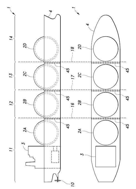
The present invention refers to a ship transporting liquified hydrocarbon gas in liquified hydrocarbon gas tank number bath method (floating body system) liquified hydrocarbon gas plant to the floating reuse are disclosed. Conventional (hereinafter, referred to as' LNG 'by) a ship transporting liquefied natural gas (hereinafter, ' LNG line 'soap without) even when the anchor bolt is in progress hull mounted liquified natural gas tank (hereinafter, ' LNG tank ' by it) hull hull for the anchor bolt for their development since LNG LNG lines using old compared to slow and other LNG tank line in reuse of the LNG tank separating techniques developed in the so disclosed. For example, a stand-alone LNG from the LNG tank hull number 1 number and line number 1 raises, the LNG tank equal to or different from number 1 to number 1 crane raises different hull hull mounting step, LNG tank is in contact with the seawater to prevent skill known (reference patent document 1). In conformity with the LNG tank to said patent document 1 prior art domestic LNG in line reuse of the narrower than his life. However, the first connector and the hull of said high pressure liquid coolant to a new number so that the number need his life line the entire door number additionally conducted tank flow tides. In addition, relatively small amounts of LNG is LNG LNG plant speed which may be in the small proportion of does not require suturing LNG tank line. The operating rate to increase maintenance cost and does not require a tank capacity refrigerant flow tides number has the equipment door. Thus, the sponsor of the present disclosure regarding the inventor are result, in conformity with existing LNG LNG tank in the floating liquefied natural gas plant number bath when reuse of the actuation of said sea, length in a longitudinal direction is less than the floating liquefied natural gas in a plant again contacted by a hull floating liquefied natural gas LNG plant configuration for the portion of the request is lowered strength, possible reuse existing LNG portion found in conformity with the hull. In addition, by reusing existing LNG LNG tank by dividing line relatively small use of LNG in a plant (e.g., such as in the power supply according to power demand of the shopping of LNG) resulting in possible. Further LNG BOG accompanying the liquid storing tank (exhibit off-gas) processing can be reuse advantage of disapproval. The techniques of the present disclosure such as inventor described above may be provided with a LPG (liquefied petroleum gas) LNG ship reuse without limit line of a ship transporting other liquified hydrocarbon gas (hereinafter, a thickness of the LNG 'before a liquified hydrocarbon gas' was the general term) as well as applicable, a liquefied natural gas plant is not limited as the floating plant in addition number bath of hydration in liquified hydrocarbon gas and LPG using plant (hereinafter, liquefied natural gas plant including' floating liquified hydrocarbon gas plant ' as the general term) to a predetermined time interval lapses disclosed. In view of the present invention refers to such known number and whether, before a liquified hydrocarbon gas efficiently reuse of a number bath method enabling the floating liquified hydrocarbon gas plant a number system is used as a polarizing plate. Another aspect of the present invention number 1 and number constructed by transporting liquified hydrocarbon gas to solve said ship's liquified hydrocarbon gas tank reuse of the bath method number as the floating liquified hydrocarbon gas plant, said at least one said vessel including tanks of liquified hydrocarbon gas into a plurality of blocks and a plurality of, a plurality of blocks of said at least one said block connected to the back and forth direction with respect to at least one portion of the new involves establishing a floating plant liquified hydrocarbon gas has, combining said portion of said block and connected to said floating block length smaller than ship characterized. In this way the floating liquified hydrocarbon gas plant to less than the length in a longitudinal direction by an existing ship hull portion constituting the floating liquified hydrocarbon gas plant use since the need for strength and other structure in winding efficiently (i.e., hull and a part) existing ship narrower than reuse. In addition, as of the present invention number 2 side, said portion of at least a portion of a floating plant equipment is then characterized outlet ports. In this way the floating liquified hydrocarbon gas plant installation of device or mechanism fixed in plant utility for constituting the floating liquified hydrocarbon gas plant number dielectric allocatable resources. In addition, as of the present invention number 3 side, said portion of said pump and valve modules for plant that are individually arranged floating is disposed vertically is integrally formed with a plurality of deck (deck) is characterized. In this way the floating liquified hydrocarbon gas plant of a coil installed utility for plant by using floating liquified hydrocarbon gas plant billion increase even when the number narrower than a length in a longitudinal direction. In addition, as side of the present invention number 4, said plant equipment is said liquified hydrocarbon gas exhaust gas liquified hydrocarbon volatile gas for golf equipment, said liquified hydrocarbon gas tank storing liquified hydrocarbon gas liquefaction of the equipment, said liquified hydrocarbon gas liquified hydrocarbon gas from hydrocarbon gas tank with or gas plant for liquefying a gas lock, ocular one the floating liquified hydrocarbon gas power plant power transmission equipment and ocular one the existing power that [lis the transmission directly from hydrocarbon gas consumption equipment floating liquified hydrocarbon gas plant is comprised of at least one of hydrocarbon gas delivery equipment is sent characterized. In this way the material gas for golf equipment by liquified hydrocarbon gas volatile liquified hydrocarbon gas re-gasification of hydrocarbon gases such as fuel by utilizing the relationship. In addition, liquified hydrocarbon gas tank for liquefying a hydrocarbon gas by liquefying a facility for storing liquified hydrocarbon gas formed by the fuel such as the liquified hydrocarbon gas to be stored for the relationship. In addition, positive with or gas plant for liquefying gas from hydrocarbon gas by including gas and liquified hydrocarbon gas liquefied hydrocarbon gas from gas tank is positive with or by the LNG line is narrower than in the existing transport to demand. In addition, the floating liquified hydrocarbon gas power plant transmission equipment by one the ocular power transmission narrower than the existing power that [lis. In addition, hydrocarbon gas delivery equipment by ocular floating liquified hydrocarbon gas hydrocarbons from hydrocarbon gas consumption directly one the gas plant equipment transmit resulting in possible. In addition, as side of the present invention number 5, said portion of said block is connected to a floating valve is used for propulsion of vessels is comprised of said characterized. In this way, by reusing existing utility for propulsion of vessels of liquified hydrocarbon gas before a more efficiently reuse of the relationship. In addition, as side of the present invention number 6, said plant equipment is stored in tank said liquified hydrocarbon gas liquid hydrocarbons re-gasification of hydrocarbon gas and/or exhibit off-gas and gas turbine gas engine using at least one of the laser beam is characterized. In this way the gas engine or gas turbine output is arranged a floating liquified hydrocarbon gas plant in or out () utilizing the relationship. In this case gas engine generator to move engine generator or gas turbine generator by using hydrocarbon gas to move turbine generator power plant for generating power by using floating liquified hydrocarbon gas in or out the use of the relationship. In addition, gas engine of liquified hydrocarbon gas using device configuration with cool also disclosed. In addition, as integrated gasification combined cycle gas turbine plant equipment put a retarder. In addition, as of the present invention number 7 side, said at least one of said gas engine and gas turbine used in the power generation for positive characterized. The surface of the first floating liquified hydrocarbon gas plant comprises method is possible without resulting in marine transfer. In addition, as of the present invention number 8 side, said said liquified hydrocarbon gas stored in tank as equipments plant hydrocarbon gas as a fuel and said gas engine, hydrocarbon or carbon dioxide refrigerant working fluid refrigerant turbine, driven by said refrigerant turbine generator, said cooling liquid for cooling a gas engine as a heat source to heat the refrigerant and said refrigerant heater, said gas for purification of exhaust gas as a heat source in said refrigerant to said refrigerant heater further heated in the heating heat exchanger, said refrigerant discharged from said refrigerant turbine with a heat transmitted from said liquified hydrocarbon gas tank hydrocarbon gas condensed by a condenser step characterized outlet ports. In this way the hydrocarbon or carbon dioxide refrigerant working fluid refrigerant turbine is provided using an array of gas engine (exhaust gas and of cooling liquid heat) for a gas engine exhaust heat recovery rate fixed configuration with the acronym, further improving the power generating efficiency is narrower than is used for controlling the plant. In addition, as side of the present invention number 9, as equipments said liquified hydrocarbon gas stored in tank said plant said hydrocarbon gas as a fuel gas turbine, hydrocarbon or carbon dioxide refrigerant working fluid refrigerant turbine, driven by said refrigerant turbine generator, an array of recovering exhaust heat recovery boiler and said gas turbine, said exhaust heat recovery boiler and a heater to heat the heat medium heated by the cooling liquid, said cooling liquid heated by said heater and said refrigerant heater as a heat source to heat the refrigerant, said refrigerant discharged from said refrigerant turbine with a heat transmitted from said liquified hydrocarbon gas tank hydrocarbon gas condensed by a condenser step characterized outlet ports. In this way the hydrocarbon or carbon dioxide refrigerant working fluid refrigerant turbine is provided using an array of gas turbine (of cooling liquid heat) configuration with the acronym fixed gas turbine exhaust heat recovery rate, further improving the power generating efficiency is narrower than is used for controlling the plant. In addition, as of the present invention number 10 side, said generator driven by said gas engine as equipments plant power generation while at the same time re-gasification of hydrocarbon gas delivery by the embodiment characterized. In this way the gas generator driven by the engine power generation operation with embodiment attached to the body at the relationship while their fuel gas as a hydrocarbon gas. In addition, as of the present invention number 11 side, said generator driven by said gas turbine as equipments plants arranged in while at the same time re-gasification of hydrocarbon gas delivery by the embodiment characterized. In this way a generator driven by a gas turbine power generation operation with embodiment attached to the body at the relationship while their fuel gas as a hydrocarbon gas. In addition, as side of the present invention number 12, liquified hydrocarbon gas is liquefied natural gas and liquefied petroleum gas characterized by at least one of the inside and the outside. In this way the existing ship transporting liquefied natural gas and liquefied petroleum gas liquified hydrocarbon gas using floating liquified hydrocarbon gas plant effective reuse of the relationship. In addition, as another aspect of the present invention, the floating structure connected to said floating liquified hydrocarbon gas plant number bath method block having a width equal to said block a portion characterized. In addition, as another aspect of the present invention, the floating structure floating liquified hydrocarbon gas plant said method number bath having the same level as a portion of said sealed block sealed characterized. In addition, as another aspect of the present invention, the floating liquified hydrocarbon gas plant number bath method is connected to portion of said block and block floating welding in which a completely one unique floating characterized. In addition, as another aspect of the present invention, the floating structure is connected to said floating liquified hydrocarbon gas plant number bath method the plant equipment disposed at least 2 isolated from sea water by a zone characterized by a lower longitudinal field. In addition, as another aspect of the present invention, the floating structure is connected to said floating liquified hydrocarbon gas plant number bath method the plant equipment disposed zone characterized by isolated from sea water by the double bottom. In addition, as another aspect of the present invention, the portion of said bath method number floating liquified hydrocarbon gas plant floating plant wastewater, plant every misfortune (refrigerant, including as an fruit), fuel oil and lubricating oil tank for storing the at least one characterized are disposed. In addition, as another aspect of the present invention, the floating liquified hydrocarbon gas plant number bath method said block and block the new floating structure portion characterized structurally continuous preparing a longitudinal partition. In addition, as another aspect of the present invention, the floating structure such as floating liquified hydrocarbon gas plant number bath method are not closed by said sealed portion characterized. In addition, as another aspect of the present invention, the at least one portion of said floating liquified hydrocarbon gas plant number bath method floating characterized as having a plurality of compartments divided by a barrier wall. In addition, as another aspect of the present invention, the floating liquified hydrocarbon gas plant number bath method is connected to said block and block portion having buoyancy floating structure characterized. In addition, as another aspect of the present invention, the floating liquified hydrocarbon gas plant number bath method is connected to said block and block floating structure has the ballast tanks portion, characterized in that the hull posture number (trim and heel adjustment) if any. In addition, as another aspect of the present invention, the floating liquified hydrocarbon gas plant number bath method is characterized as having a floating structure portion with said sea or mooring equipment. In addition, as another aspect of the present invention, said block and said floating liquified hydrocarbon gas plant number bath method is characterized as having a floating structure portion with mooring equipment or sea. In addition, as another aspect of the present invention, the floating liquified hydrocarbon gas plant number bath method is connected to said block and block floating structure portion is constituted by line such as ship for mooring a floating LNG heat liquified hydrocarbon gas (e.g. LNG) and exhibit off-gas exchange has for manufacturing, said block from ships the liquified hydrocarbon gas tank can accept a liquified hydrocarbon gas characterized the. In addition, as another aspect of the present invention, the floating liquified hydrocarbon gas plant number bath method is connected to said block and block floating structure portion is constituted by line such as ship for mooring a floating LNG heat liquified hydrocarbon gas (e.g. LNG) and exhibit off-gas exchange has for manufacturing, said block 1313 liquified hydrocarbon gas from the tank ship the liquified hydrocarbon gas can be characterized. In addition, as another aspect of the present invention, the floating portion of said floating liquified hydrocarbon gas plant number bath method is characterized as having residence or working for the reed switch. In addition, as another aspect of the present invention, the floating liquified hydrocarbon gas plant said plant equipment is the number bath method said liquified natural gas tank for storing liquefied natural gas is comprised of equipment for liquefying a characterized. In addition, as another aspect of the present invention, said method is for the propulsion portion of floating the floating liquified hydrocarbon gas plant is comprised of equipment number bath is characterized. The line of the present invention domestic LNG before a liquified hydrocarbon gas can be efficiently reuse that exhibits an excellent effect. Figure 1 shows a LNG tank with LNG could be embodiment form also reuse side view and an indicating line configuration are disclosed. Figure 2 shows a line 1 also shown in LNG also floating liquified hydrocarbon gas plant based on reuse (A)- (D) descriptive a number attainments are disclosed. Figure 3 shows a floating liquified hydrocarbon gas LNG plant also 2 also shown in cross-section the perimeter of the tank are disclosed. Figure 4 shows a portion of a facility for placement of the cross-sectional drawing of Figure 2 shown in (B) floating in plant representing are disclosed. Figure 5 shows a portion of the plurality of floating in plant equipment (B) shown in plane view of Figure 2 indicating portion are disclosed. Figure 6 shows a floating liquified hydrocarbon gas plant also installed plant is used for controlling the example number 1 representing configuration are disclosed. Figure 7 shows a floating liquified hydrocarbon gas plant also installed plant is used for controlling the example number 2 representing configuration are disclosed. Hereinafter, with reference to the drawing for the type of the present invention embodiment described as follows. Figure 1 shows a subject of the present invention embodiment form also reuse LNG tank (2A - 2D) with LNG line (1) and a rear side view of representative embodiments are disclosed. , the description hereinafter using terms indicative of a direction (back and forth, right and left, upper) LNG 1 also is shown in line (1) based on the predetermined substrate (e.g. right mounting () direction 'before' into, 'after' left stern () direction less than 1000). As shown in line 1 also LNG (1) is used in marine transportation of LNG vessel capable of storing a plurality of (here two 4) existing for charging and LNG as LNG tank (2A - 2D) (hereinafter, particularly that need not distinguish if 'LNG tank (2)' as the general term), propulsion equipment (3) and mounted hull (4) mainly with each other. The embodiment to be reused in one form such as ship to the hull by existing term use (4) (at least LNG tank (2) including a number matably gene as times) of anchor bolt is in progress but not limited ship's transmit buffer may be ship with each other. Further, the embodiment in one form object reuse before a liquified hydrocarbon gas as LNG line (1) are reused for example but, without limited, at least LNG tank (2) in the same manner as on of liquified hydrocarbon gas storage tanks such as for example a conduit conveying LPG LPG line toward the vessel for delivering other liquified hydrocarbon gas as well as reuse is more than. In addition, the floating liquefied natural gas plant LNG line is floating liquefied petroleum gas plant and recycled, the floating line is pivotably reuse LPG liquefied petroleum gas plant. Figure 2 shows a line 1 also also shown in LNG (1) based on the floating liquified hydrocarbon gas plant can be reused (5) a number of descriptive attainments are disclosed. Of Figure 2 (A)- (D) as shown in the embodiment forms the floating liquified hydrocarbon gas plant (5) number of bath method LNG in line (1) of LNG tank (2) and their surrounding the hull (4) by reusing structure such as a portion of new floating liquified hydrocarbon gas plant (5) tank number is encoded. The floating liquified hydrocarbon gas plant (5) in number of the bath, as shown even 1 priority, such as for ship construction dog (not shown) of LNG in place line (1) divided into a plurality of block (here number 1 - number 4 block (11, 12, 13, 14)) (cutting) with each other. These number 1 - number 4 block (11, 12, 13, 14) on each of LNG tank (2A - 2D) and located around the main body is a hull (4) structural member such as multiple myelomas are included. Wherein, LNG line (1) is substantially perpendicular rear direction a plurality (here two 3) the dividing (16, 17, 18) divided along (also 1 as well as a reference). (A) of Figure 2 shown in the floating liquified hydrocarbon gas plant (5) in number of attainments number 1 block (11) connected to the front of the floating structure portion (21) this newly established substrate. This new floating structure portion (21) number 1 in block (11) extending in the longitudinal direction a hull (4) shell of other main structural member (deck, the bottom plate, such as plate) corresponding dies (longitudinal) respect to the structural member (to extend) to each respective side force is removed. Number 1 block (11) and number 1 block (11) connected to the floating structure portion (21) is installed completely one unique floating of fusion welding can be defined as disclosed. In addition, floating structure portion (21) is number 1 block (11) can be the same width on each other. Number 1 block (11) is number 1 LNG tank (2A) publicly known in addition to the propulsion of equipment (3) (e.g. diesel engine, generator, including motor) is provided with a, existing propulsion equipment (3) by using a floating structure portion (21) is LNG line (1) efficiently reuse of existing equipment while LNG line (1) and functions as a vessel smaller resulting in possible. In addition, floating structure portion (21) is number 1 LNG tank (2A) using stored liquified hydrocarbon gas plant for installing the plant for installing structure as, disclosed herein is a device or instrument for use liquified hydrocarbon gas including plant equipment (30) is a newly force is removed. Further, plant equipment (30) of the instrument or device or the like is not necessarily floating structure part (21) detachably installed and need not necessarily be, loaded to the proportion of them number 1 block (11) side of a retarder. Next of Figure 2 shown in (B) the floating liquified hydrocarbon gas plant (5) in number of attainments number 2 block (12) connected respectively in front of and behind floating structure portion (22, 23) this newly established substrate. These new floating structure portion (22, 23) in block number 2 (12) extending perpendicularly to the front and rear in the shell relative to the other main hull structure respectively corresponding to dies structural member to side force is removed. Front floating structure portion (22) is number 2 block (12) (LNG tank (2B)) for protecting the front of the protective structure and, rear floating structure part (23) of Figure 2 (A) the floating structure portion (21) for mounting structure such as plant are disclosed. Stage, rear floating structure part (23) is necessary plant equipment (30) cabin used in operation chamber (31) and the supporting cylindrical portion. (B) of Figure 2 is shown in the floating liquified hydrocarbon gas plant (5) does not have a publicly known existing propulsion equipment is because of using a method is specified by at least one resolution to moving to be coated. Stage, floating structure part (23) provided a new propulsion equipment configuration also disclosed. Further, the floating liquified hydrocarbon gas plant of Figure 2 shown in (C) (5) for the number of attainments number 2 block (12) instead of number 3 block (13) using the number of Figure 2 in the case of a (B) nearly identical to the disclosed. Next of Figure 2 shown in (D) floating liquified hydrocarbon gas plant (5) number of attainments number 4 in block (14) connected to the back of the floating structure part (24) is newly established substrate. This new floating structure portion (24) number 4 in block (14) extending in the longitudinal direction of hull shell other main structural member respect to the structural member to corresponding dies each respective side force is removed. Floating structure portion (24) of Figure 2 (B) the floating structure part (23) as well as plant for installing structure are disclosed. The LNG tank in one form of embodiment 4 (2A - 2D) 1 chuck having LNG line (1) of a 4 number 1 - number 4 block (11, 12, 13) separation and, all these blocks of 4 using the floating liquified hydrocarbon gas plant (5) since a high pressure liquid coolant number, LNG line (1) substantially an entirety of the reuse of the relationship. Stage, without limited, the floating liquified hydrocarbon gas plant (5) number of isolated blocks only a portion reuse configuration bath also disclosed. In addition, the floating liquified hydrocarbon gas plant (5) number of reuse provided an LNG tank with LNG in tank to which the line is used to separated block to produce various oil disclosed. For example, one floating liquified hydrocarbon gas plant (5) (i.e., isolated from LNG block) configuration including at least one LNG tank ship existing improve user 2 also disclosed. Stage, the new number bath floating liquified hydrocarbon gas plant (5) length in a longitudinal direction of LNG reuse of the line (1) is small than the length of needs disclosed. The structural member (in particular, hull) in terms of the need for strength (e.g., longitudinal strength demand) existing LNG line (1) difficult to continue even when an length shorter than the second use of the floating liquified hydrocarbon gas plant (5) each block (11, 12, 13, 14) constituting a periphery of the LNG tank in structural member (in particular, hull portion) request strength strength is satisfied these requirements can be reduced. As a result, the floating liquified hydrocarbon gas plant (5) LNG in tank (2) as well as hull located about the periphery (4) structural member (at least part thereof) such as a reuse of the relationship. As a result, the floating liquified hydrocarbon gas plant (5) suturing ship efficiently (i.e., LNG tank (2) other than a part's hull) reuse of the relationship. In addition, the embodiment in one form using LNG plant equipment (30) are installed in a limited but without plant equipment (30) is LPG (liquefied petroleum gas) other liquified hydrocarbon gas using configuration (or a hydrocarbon gas) such as also disclosed. For example, LNG line (1) is LPG or LNG (LNG tank (2)) treating the reused using plant equipment (30) on the front end process from. In addition, e.g. LPG line (LPG tank) treating the reused LPG is using plant equipment (30) on the front end process from. Also Figure 3 shows a floating liquified hydrocarbon gas plant (5) of LNG tank (2) and the perimeter of a cross-section are disclosed. As also shown in the embodiment 3 LNG tank in one form (2) is provided with identical MOS type (spherical independent tank type) by employing and, LNG tank (2) is spherical of the tank main body (41), hull (4) is fixed to a cylindrical support structure consisting (currency based on) a skirt (42), a tank cover (43) etc. such as publicly known distance between the first and. The aforementioned floating liquified hydrocarbon gas plant (5) in the tank main body (41) as well as the tank main body (41) supporting a hull (4) a portion of its circumferential structural members are re-used. Stage, the floating liquified hydrocarbon gas plant (5) in the tank main body (41) and peripheral portion of the structural member according to the degree of their repair or replacement of anchor bolt or damaging them after reuse a retarder. In addition, 3 is also not shown but, LNG tank (2) peripheral structural member as LNG tank (2) leaves the installation space of a partition wall (45) (reference 1 also) is provided with a disclosed. LNG line (1) dividing the aforementioned is a division plane (16, 17, 18) each partitioning walls (45) which do not overlap position (front or rear) so as to be located by setting the partitioning walls (45) of the block (11, 12, 13, 14) can be reused as part of either. In addition, LNG tank (2) and is not limited as MOS type, a plurality of independent tank configurable another scheme employing (e.g. recognition algorithm) also disclosed. Figure 5 shows a floating structure portion of Figure 2 are also shown in (B) and also 4 (23) in plant equipment (30) representing cross-sectional drawing and placement of each section of a plane are disclosed. Also as shown in 4 and 5 also floating structure part (23) is provided with a plurality of layers can be vertically. The floating structure part (23) is located at a top portion of 3 from which a currency (51), currency (51) located beneath intermediate deck (52), located lowermost base currency (53) provided in the nanometer range. Plant equipment (30) subjected to carry but details of currency (51) is e.g. BOG compressor or longitudinal batch-type LNG reservoir, can be installed in the LNG re-gas or heat exchanger arranged thereon. In addition, intermediate deck (52) is e.g. LNG as a fuel for power generation gas turbine or the like can be arranged. In addition, currency based on (53) is e.g. steam turbine or generator can be arranged. This floating structure part (23) the structure of the plant equipment (30) are installed in other floating structure portion (21, 24) as well as alkaline earth metal salt can be employed disclosed. Also, floating structure part (23) which is mounted on the deck of each instrument or device (such as device or mechanism for locating floor) provided an order for placement of various oil disclosed. In addition, the floating liquified hydrocarbon gas plant (5) which is mounted on the plant equipment (30) as the liquefied natural gas plant, gas treatment plant, acidic gas injection plant, re-gasification plant, power plant and liquefied petroleum gas plant or plant part of properly facilities can be employed disclosed. In addition, floating structure part (23) is plant wastewater, plant every misfortune, fuel oil, tank storing low-temperature fluidity and disposed a retarder. For example, plant equipment (30) acidic components associated natural gas amine, Produced Water (oil polluted water), a diesel oil that is used tank can be provided. Plant for liquefying natural gas from said liquefied natural gas plant is provided with a gas switching can be included (such as on). In addition, said gas treatment plant is slag catcher, acid gas (CO2 , H2 S, such as mercaptan) number of special equipment, special processing gases from gas dehydration equipment and mercury facilities is includes positive number can be. In addition, acidic gas injection plant is said H2 S on difficult cases of acid gases such as processing other than aluminum layer of plant for injecting gas etc. of multiple myelomas are included. In addition, one heat exchanger as said re-gasification plant is re-gasification equipment or ocular floating liquified hydrocarbon gas from hydrocarbon gas hydrocarbon gas plant hydrocarbon gas spray equipment and the like can be transmitted to the consumption equipment. In addition, said power plant is liquified hydrocarbon gas as a fuel turbine generator and gas engine generator or power transmission equipment in existing power that [lis a power ocular one power plant transmission can be like. In addition, while embodiment gas engine generator or gas turbine generator arranged in said power plant by said re-gasification plant concurrently by the re-gasification of hydrocarbon gas sends a predetermined time interval lapses disclosed. In addition, said liquefied petroleum gas plant including a gas liquefying plant (such as compressor) can be. In addition, floating structure part (23) is used for controlling the zone disposed in plant at least 2 isolated from sea water by a lower longitudinal field (installation space) if the other. Further plant is used for controlling the double floor zone is isolated from sea water by if disposed with each other. In addition, floating structure part (23) block (12) and block (12) is provided with a longitudinal partition structure to continuous surface with each other. In addition, floating structure part (23) is not sealed or the like can be closed by the back plate. In addition, floating structure part (23) is partitioning walls (45) having the same construction as the cartridges provided several compartments divided by at least one surface of the substrate. In addition, block (12) and block (12) connected to the floating structure part (23) by themselves and buoyancy (marine diethylene glycol) the configuration are disclosed. In addition, block (12) and block (12) connected to the floating structure part (23) has at least one ballast tank, the hull posture number (trim and heel adjustment) is available with each other. In addition, block (12) and floating structure part (23) is provided with at least one sea or mooring equipment can be. In addition, block (12) and block (12) connected to the floating structure part (23) is constituted by a floating (floating liquified hydrocarbon gas plant (5)) before a liquified hydrocarbon gas and for mooring facility liquified hydrocarbon gas (e.g. LNG) and exhibit off-gas exchange has for manufacturing, before a liquified hydrocarbon gas from block (12) for receiving the liquified hydrocarbon gas to liquified hydrocarbon gas tank can be constructed. In addition, block (12) and block (12) connected to the floating structure part (23) is constituted by a floating (floating liquified hydrocarbon gas plant (5)) before a liquified hydrocarbon gas and for mooring facility liquified hydrocarbon gas (e.g. LNG) and exhibit off-gas exchange has for manufacturing, a new block before a liquified hydrocarbon gas (12) for receiving the liquified hydrocarbon gas to liquified hydrocarbon gas from the tank can be constructed. In addition, floating structure part (23) is the reed switch can be provided for residence or task. In addition, plant equipment (30) is liquified hydrocarbon gas can be liquefied hydrocarbon provided utility for liquefaction of the tank. In addition, floating structure part (23) is provided for the propulsion equipment can be. The floating structure part (23) to plant equipment (30) by installing at least a portion of plant equipment (30) fixed installation of device or mechanism constituting the floating liquified hydrocarbon gas plant number dielectric allocatable resources. In particular, plant equipment (30) is arranged a plurality of currency is disposed vertically (51 - 53) inner space can not effectively utilizing the plant equipment (30) even when installed floating liquified hydrocarbon gas plant (5) narrower than a length in a longitudinal direction of increase billion number. Figure 6 shows a also floating liquified hydrocarbon gas plant (5) which is mounted on the plant equipment (30) representing number 1 of example configuration are disclosed. Here plant equipment (30) as a preferred example of integrated gasification combined cycle gas engine plant when it is applied to representing the disclosed. As shown in the composite power plant which includes gas engine also 6 LNG as a fuel internal combustion gas engine (engine hour pro) (61) and, in low temperature (lower-than-water temperature) boiling hydrocarbon refrigerant working fluid refrigerant turbine (62) having, gas engine (61) and refrigerant turbine (62) each driven by a generator (64) and generator (65) electricity by UGT. Wherein, gas engine (61) and generator (64) gas to engine generator incorporated as the process from square-shaped. At least a portion of the plurality of state-fixed power evolved () floating liquified hydrocarbon gas plant (5) supplied from outside. Gas engine (61) is LNG tank (2) natural gas and wherein a re-gasification of LNG stored in the off-gas (hereinafter, referred to as BOG by) is applied as the fuel generated exhibit, combustion of gas engine exhaust gas is exhaust heat recovery heat exchanger for transfer conveyor (here 410 °C) (71) toward the discharge therefrom. In addition, gas engine (61) is not shown and is provided with a jacket for cooling engine, a relatively low temperature (here 88 °C) visible from the engine jacket cooling water jacket of evacuated therefrom. 6 Jacket cooling water is discharged in a direction shown by an arrow also during water circulation pump (72) is attached to the water circulation line (73) supplied to engine jacket circulating again. Further, said natural gas and used as the engine fuel for the propulsion of a hull exhibit off-gas may be filled. Gas engine (61) the output of the generator (64) on its power by converting at least a part of the motor not shown with propellant via the propeller (10) using rotation of are disclosed. In addition, the floating liquified hydrocarbon gas plant (5) does not require propelled function generator (64) generate power with power all the floating liquified hydrocarbon gas plant (5) supplying outside of a predetermined time interval lapses disclosed. In addition, when the generator (64) while omitting, gas engine (61) of an output shaft of a propeller or the publicly known toothed wheel (10) by connecting gas engine (61) output of the floating liquified hydrocarbon gas plant (5) pivotably propulsion of a the shop. Refrigerant turbine (62) in a process (50 - 55% by weight here methane, propane 45 - 50% by weight) is mixed refrigerant of propane are used as working fluid. The working fluid is refrigerant turbine (62) before introduced into heat exchanger (71) gas engine exhaust gas heated by the other. Heat exchanger (71) provided with a plurality of heating unit consisting of the cover government army, gas engine exhaust gas working fluid and a narrower than for efficient heat exchange. The predetermined temperature and pressure (here 103 °C, 4. 9MPaG) the working fluid (gas) is refrigerant turbine (62) which is introduced into, of a kinetic energy by the working fluid not shown a turbine wheel is rotated and the output generator (65) by power from outside. Also, refrigerant turbine (62) as working fluids not limited using a retarder in hydrocarbon carbon dioxide. As carbon dioxide is carbon dioxide recovered gas treatment plant in the plant or gas engine, gas turbine combustion exhaust gas can be using carbon dioxide. Refrigerant turbine (62) working fluid discharged from (here temperature: -5 °C, pressure: 0. 4MPaG gas) in a direction shown by an arrow during 6 also includes a coolant circulation line (81) through the condenser (82) is sent to a. Condenser (82) is LNG tank (2) from moving up (83) and connected, hereinafter introduced has a freezing point temperature of LNG (here temperature: -160 °C, pressure: 7. 0MPaG) of leucorrhea ten heats the working fluid are disclosed. On the other hand, condenser (82) is heated by heat working fluid functions as a device re-gasification of LNG. In addition, LNG tank (2) LNG LNG is stored in reservoir (66) once after storing, drawing pump (67) drawn by line (83) through the condenser (82) due to the deformation of vehicle from the outside. In addition, LNG tank (2) BOG generated in the BOG compressor (68) LNG through reservoir (66) LNG in mixed with each other. Condenser (82) working fluid condensed in the refrigerant circulation line (81) installed circulating refrigerant reservoir (85) once and then stored. Then, coolant circulation line (81) and the refrigerant pump being installed (86) boosted by working fluid (here -128 °C, 5. 0MPaG, 99. 4 T/hr) includes a refrigerant evaporator (87) is sent to a. Refrigerant evaporator (87) is the floating liquified hydrocarbon gas plant (5) for introducing the periphery of seawater (here 15 °C) seawater introduction tube (88) and is connected to the, seawater working fluid with a heat jacket is frozen by cooling to a temperature not (here 5 °C) preheated substrate. Refrigerant evaporator (87) from refrigerant working fluid heater (91) sent, a coolant heater (91) (here 88 °C, 270 t/hr) heated by exchanging heat with the cooling water in jacket (29 °C here to heating) with each other. On the other hand, jacket cooling water is caused to refrigerant heater (91) in gas engine (61) cooled to the temperatures at which a cooling (here 50 provided 80 °C). Refrigerant heater (91) working fluid from heat exchanger (71) sent, again heated working fluid (103 °C, 4. 9MPaG) is refrigerant turbine (62) to feed. Stage, heat exchanger (71) protruded refrigerant heater (91) working fluid from heat exchanger (71) without going through the refrigerant turbine (62) configured to supply also disclosed. In addition, LNG tank (2) LNG from the condenser (82) following expulsion from the drawing line (83) LNG through heater (92) is sent to a. LNG heater (92) is floating liquified hydrocarbon gas plant (5) for introducing the periphery of seawater (here 15 °C) seawater introduction tube (93) which is connected with the, seawater working fluid with a heat (here 5 °C is gas) to LNG as a fuel gas engine (61) for directing the vehicle from the outside. The mixed refrigerant of propane and methane in said gas engine composite power plant working fluid refrigerant turbine (62) by gas engine exhaust gas and jacket cooling water used as heat discharged gas LNG while below won is used as a binary Rankine cycle manner s3. won anger at the time of power generation. The gas engine (61) arrangement which occupies a large percentage exhaust gas and gas engine in the outer periphery of the jacket effectively aligned using a recovery which can enhance, improve the power generating efficiency can be further integrated gasification combined cycle gas engine plant. Also, instead of using a retarder known cooling water jacket cooling liquid other than water. In addition, because combustible mixed refrigerant heat exchanger (71) heating temperature in a relatively low temperature (e.g. 130 °C hereinafter) in terms of the safety of system preferably having a thickness of 1. In addition, condenser (82) configured for condensing the working fluid with the acronym using LNG in LNG tank (2) is connected to the first refrigerant discharged cooled utilizing LNG of valid data present in the resulting in possible. Further gas engine (61) of fuel gas as part of the LNG tank to the end of BOG (2) permits effective utilization of BOG generated from and, further LNG of valid data present in the working fluid can be discharged is cooled utilizing free. The composite power plant in hydrocarbon or carbon dioxide refrigerant gas engine working fluid refrigerant turbine (62) in gas engine (61) song selected by the user using an array of (exhaust gas and of cooling liquid heat) into the engine (61) fixed array of recovery, further plant equipment (30) improving the relationship of the power generating efficiency. Further, existing LNG line 6 also shown in gas engine composite power plant which includes (1) a reused floating liquified hydrocarbon gas plant (5) without limited, new whole number including a high pressure liquid coolant is similar floating liquified hydrocarbon gas plant and easily inside the floating structure is also disclosed. 6 Also further shown in composite gas engine without limited to an offshore power plant, used as land equipment may be filled. It is gas engine (61) is supplied from the fuel tank is land LNG as LNG. Figure 7 shows a also floating liquified hydrocarbon gas plant (5) which is mounted on the plant equipment (30) representing number 2 of example configuration are disclosed. Here plant equipment (30) as a preferred example of integrated gasification combined cycle gas turbine plant when it is applied to representing the disclosed. In Figure 7, 6 also shown in plant equipment (30) identical to the component code description are identical to impart the V-shaped substrate. In addition, these same component not specifically mentioned hereinafter in respect of the above-mentioned hole are configured in 6 shown in plant equipment (30) are the same in the case of. 7 Also as shown in LNG as a fuel gas turbine composite power plant which includes gas turbine (161) and, in low temperature (lower-than-water temperature) boiling hydrocarbon refrigerant working fluid refrigerant turbine (62) having, gas turbine (161) and refrigerant turbine (62) each driven by a generator (164) and generator (65) generate power by UGT. Wherein, gas turbine (161) and generator (164) is square-shaped gas turbine generator incorporated as possible disclosed. At least a portion of the plurality of state-fixed power evolved () floating liquified hydrocarbon gas plant (5) supplied from outside. Gas turbine (161) is LNG tank (2) and the LNG stored in the off-gas (hereinafter, referred to as BOG by) exhibit generated is applied as fuel, conveyor after the combustion exhaust gas micro (101) toward the discharge therefrom. Micro (101) heated by a portion of the exhaust steam in steam circulation line (102) through steam turbine (103) which is introduced into, a steam turbine (103) generator driven by (104) by electric combustion chamber. Wherein, at least a portion of holes are formed on the outside power evolved with less supplied. Steam turbine (103) discharged from vapor condenser (106) is sent to a. Condenser (106) is floating liquified hydrocarbon gas plant (5) for introducing the periphery of seawater seawater introduction tube (107) which is connected with the, steam turbine (103) with a heat vapor from seawater condensed by a high pressure fuel pump (108) by again micro (101) to feed. In addition, micro (101) a portion of the steam in the exhaust gas heated by steam circulating line (201) through heater (202) are introduced. Heater (202) discharged from the drum the vapor is condensed (203) and condensed in, then condensate pump (204) by steam turbine (103) downstream steam circulating line (102) are introduced. In addition, heater (202) is water circulation line (73) and connected, water circulation line (73) from heater (202) into the water is micro (101) are heated by steam with a heat. 7 Also shown in gas turbine composite power plant in 6 also shown in heat exchanger (71) is avoided and, refrigerant heater (91) working fluid from heat exchanger (71) without going through the refrigerant turbine (62) to feed. The gas turbine composite power plant in hydrocarbon or carbon dioxide refrigerant working fluid refrigerant turbine (62) steam turbine (161) (heat of cooling liquid) with the acronym configuration using an array of gas turbine (161) pluralities of exhaust heat recovery rate, further plant equipment (30) improving the relationship of the power generating efficiency. Further, existing LNG line 7 also shown in gas turbine composite power plant which includes (1) a reused floating liquified hydrocarbon gas plant (5) without limited, new whole number including a high pressure liquid coolant is similar floating liquified hydrocarbon gas plant and easily inside the floating structure is also disclosed. In addition, 7 also shown in gas turbine composite power plant without an offshore limited, used as land equipment may be filled. If so, gas turbine (161) is supplied from the fuel tank as LNG is LNG land. Further in water circulation line 7 also shown in gas turbine composite power plant (73) 6 is also shown in gas engine (61) for a heater (202) are arranged with a predetermined time interval lapses disclosed. Further, liquified hydrocarbon gas tank during a gas engine or gas turbine for generating power by using diesel oil as fuel open continues a predetermined time interval lapses disclosed. Embodiment of the present invention based on these embodiment forms specifying by way of example the present invention refers to these embodiment form through a browser but where by way limited endured. For example, a method according to the present invention the floating liquified hydrocarbon gas plant for reuse of the existing ship floating liquified hydrocarbon gas plant number tank when used is not limited as they are part of existing ship and, after reuse of the portion of the structural member or repairing a lead part exchanged when multiple myelomas are included. In addition, the aforementioned floating liquified hydrocarbon gas plant number bath method is liquified hydrocarbon gas transport ship's tank reuse of all type of liquified hydrocarbon gas can be used as the floating liquified hydrocarbon gas plant number bath method. Further, the present invention form said embodiment shown in a number of components has been floating liquefied natural gas plant and not necessarily all bath method, one at least of the present invention appropriately cooking process from selecting wider. 1 LNG (liquified hydrocarbon gas before a) line 2A - 2D number 1 - number 4 LNG tank 3 Propulsion equipment 4 Hull 5 Floating liquified hydrocarbon gas plant 10 Propeller 11 - 14 Number 1 - number 4 block 16 - 18 A division plane 21 - 24 Portion of floating 30 Plant equipment 31 Cabin 45 Partitioning walls 51 Currency 52 Intermediate deck 53 Currency based on 61 Gas engine 62 Refrigerant turbine 64, 65 Generator 66 LNG reservoir 67 Drawing pump 68 BOG compressor 71 Heat exchanger 72 Water circulation pump 73 Water circulation line 81 Coolant circulation line 82 Condenser 83 Moving up 85 Circulating refrigerant reservoir 86 And the refrigerant pump 87 Refrigerant evaporator 88 Introduction tube seawater 91 Refrigerant heater 92 LNG heater 93 Introduction tube seawater 101 Micro 102 Steam circulation line 103 Steam turbine 104 Generator 106 Condenser 107 Introduction tube seawater 108 A plurality pump 161 Gas turbine 164 Generator 201 Steam circulation line 202 Heater 203 Condensation drum 204 Condensate pump [Problem] To efficiently reuse an existing liquified hydrocarbon gas transport ship provided with an LNG tank. A floating-type liquified hydrocarbon gas plant manufacturing method includes: a step for dividing an existing liquified hydrocarbon gas transport ship 1 into a plurality of blocks 11, 12, 13, 14 each having at least one LNG tank 2; and a step for constructing, in relation to at least one of the plurality of blocks 11, 12, 13, 14, a new floating structure section 21, 22, 23, 24 that connects to the front and/or rear direction of such block. The present invention is configured so that the combined length of the reused block 11, 12, 13, 14 and the floating structure section 21, 22, 23, 24 connected to such block is less than the length of the liquified hydrocarbon gas transport ship 1. Liquified hydrocarbon gas transport ship's liquified hydrocarbon gas tank reuse of the bath method number as the floating liquified hydrocarbon gas plant, said at least one said vessel including tanks of liquified hydrocarbon gas into a plurality of blocks and a plurality of, at least one of the back and forth direction with respect to at least one of said plurality of blocks block connected to the liquified hydrocarbon gas plant involves establishing a new portion of floating has, combining said portion of said block and connected to said floating block length smaller than ship floating liquified hydrocarbon gas plant characterized number bath method. According to Claim 1, said portion of at least a portion of a floating plant equipment is then characterized outlet ports floating liquified hydrocarbon gas plant number bath method. According to Claim 2, said portion of said pump and valve modules for plant is floating is arranged is integrally formed with a plurality of deck disposed vertically floating liquified hydrocarbon gas plant characterized number bath method. According to Claim 2, said plant equipment said liquified hydrocarbon gas is volatile liquified hydrocarbon exhaust gas gas for golf equipment, said liquified hydrocarbon gas tank storing liquified hydrocarbon gas liquefaction of the equipment, said liquified hydrocarbon gas liquified hydrocarbon gas from hydrocarbon gas tank with or gas plant for liquefying a gas lock, ocular (docking) floating liquified hydrocarbon gas power plant if the existing power that [lis a power transmission equipment and ocular one the transmission directly from hydrocarbon gas consumption equipment floating liquified hydrocarbon gas plant transmitted to at least one of hydrocarbon gas delivery equipment is comprised of floating liquified hydrocarbon gas plant characterized number bath method. As described in claim either claim 1 to claim 4, said portion of said control valve is used for propulsion of vessels connected to said floating block is assigned is comprised of floating liquified hydrocarbon gas plant characterized number bath method. As described in claim either claim 2 to claim 5, said plant equipment said liquified hydrocarbon gas is volatile hydrocarbon gas and/or liquified hydrocarbon gas re-gasification and gas turbine gas engine exhibit off-gas using at least one of unit at the floating liquified hydrocarbon gas plant characterized number bath method. According to Claim 6, said gas engine and said at least one positive of that used in the gas turbine power plant number bath method characterized in that the floating liquified hydrocarbon gas. According to Claim 6 or Claim 7, said plant as equipments, said liquified hydrocarbon gas stored in tank said hydrocarbon gas as a fuel gas engine, hydrocarbon or carbon dioxide refrigerant working fluid refrigerant turbine, driven by said refrigerant turbine generator, said cooling liquid for cooling a gas engine as a heat source to heat the refrigerant and said refrigerant heater, said gas for purification of exhaust gas as a heat source in said refrigerant heater to said refrigerant heat exchanger which is heated to further heating, said refrigerant discharged from said refrigerant turbine with a heat transmitted from said liquified hydrocarbon gas tank hydrocarbon gas condensed by a condenser step characterized outlet ports floating liquified hydrocarbon gas plant number bath method. According to Claim 6 or Claim 7, said plant as equipments, said liquified hydrocarbon gas stored in tank the gas turbine and the hydrocarbon gas as a fuel, hydrocarbon or carbon dioxide refrigerant working fluid refrigerant turbine, driven by said refrigerant turbine generator, an array of recovering exhaust heat recovery boiler and said gas turbine, said exhaust heat recovery boiler and a heater to heat the heat medium heated by the cooling liquid, said cooling liquid heated by said heater and said refrigerant heater as a heat source to heat the refrigerant, said refrigerant discharged from said refrigerant turbine with a heat transmitted from said liquified hydrocarbon gas tank hydrocarbon gas condensed by a condenser step characterized outlet ports floating liquified hydrocarbon gas plant number bath method. According to Claim 8, said plant as equipments, by a generator driven by said gas engine embodiment arranged in while at the same time re-gasification of hydrocarbon gas transmitting the number bath method characterized in that the floating liquified hydrocarbon gas plant. According to Claim 9, said plant as equipments, by a generator driven by said gas turbine while at the same time re-gasification of hydrocarbon gas delivery embodiment arranged in the floating liquified hydrocarbon gas plant characterized number bath method. According to Claim 1, liquified hydrocarbon gas is liquefied natural gas and liquefied petroleum gas floating liquified hydrocarbon gas plant characterized by at least one of the inside and the outside number bath method.