Improvements with the benches of moulding of hollow plastic body by blowing, of the oscillating type.
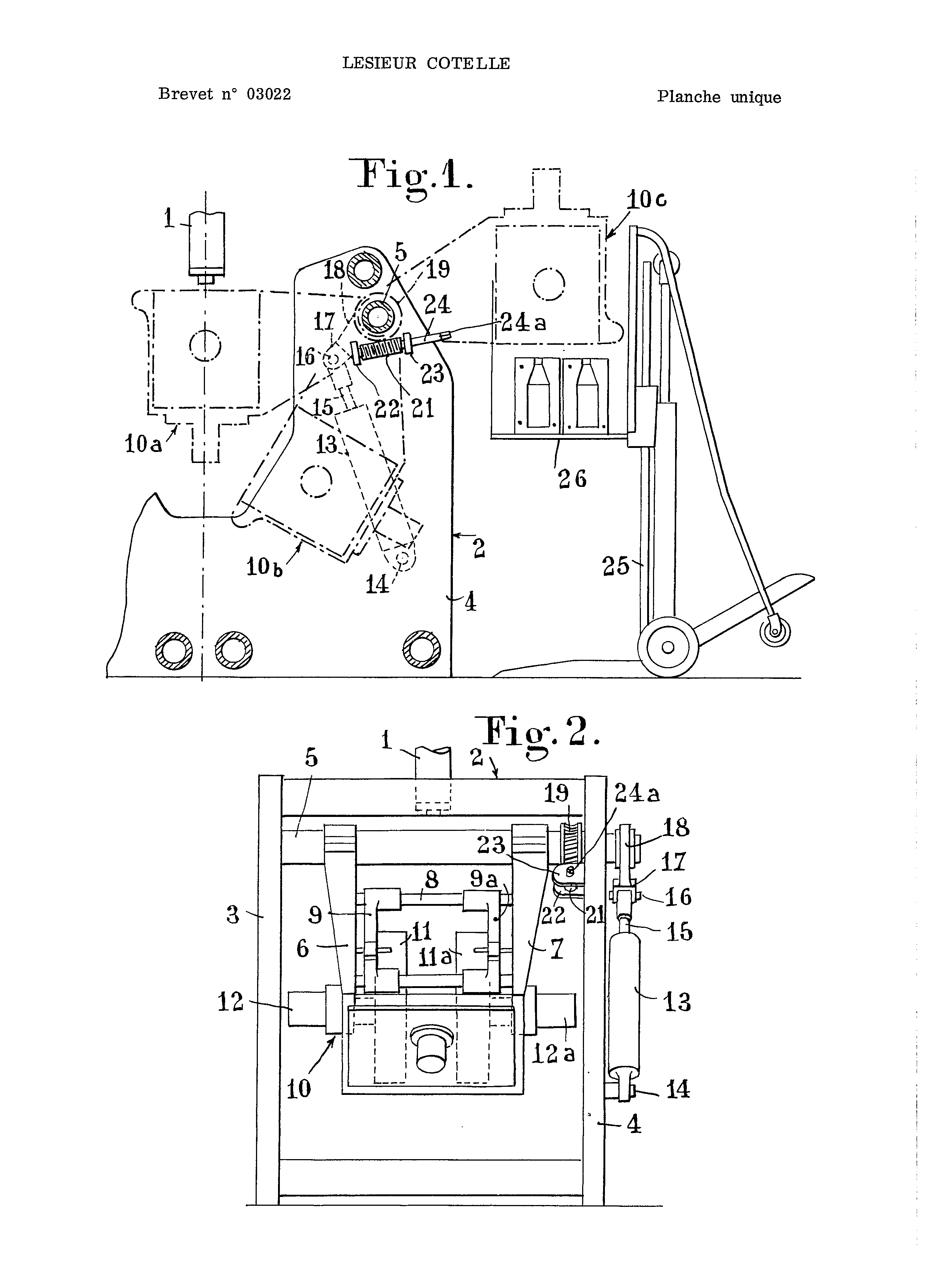
PATENT AS AFRICAN AND MALAGASY INDUSTRIAL PROPERTY P. 887 in Yaounde (Cameroon " International Patent Classification: 29 № 03022 b. O A'm w. THE I. 15 To 40 hr 17 March 1969 requestedmin the O.A.M.P.I. (G.P. no. 53,549) by the company anonymous said: Sieur corded residing in France. 15 DECEMBER 1970 PROVIDES THE Published at no. 5 of 1970 official ballot PRIORITY: Patent application filed in France under the no. 144,212 18 March 1968 on behalf of the firm anonymous said: ELCO company operating-LeSieur corded & FOUCHER. The present invention relates to improved banks body molding hollow plastic blow, the swing type. A known molding machine plastic hollow body blow, which essentially comprises a vertical-axis extruder having associated therewith at least one bench type molding oscillating. This bench comprises essentially a pair of racks parallel movable between which there are slidably mounted of platens and forming a dimensionally stable assembly integral with a horizontal oscillating shaft that is journaled to the top of the fixed frame of the bench. The oscillating assembly moves between two extreme positions, namely a high position, corresponding to the horizontal, wherein the extruded parison is pinched between the molds, and a low position in which the molds are opened and the molded articles are ejected. The oscillating motion is generally controlled by a reciprocating drive device comprising a hydraulic cylinder. The present invention provides an improvement to this type of bench molding in order to facilitate the operation of changing mold while increasing the EFS VBE1 irity during this operation. To this end, this bank from aqueous solutions plastic blow, the swing type, comprising a mold station integral with an oscillating shaft that is journaled on a fixed frame and which is coupled to a reciprocating drive, is characterized in that the rocker arm is further coupled, via a reduction gear train, to a manually operated shaft rotatably mounted on the fixed frame. When a change of mold is to be performed, it is sufficient to disengage the oscillating shaft of its drive device and manually rotating the control shaft for pivoting the entire assembly mold support outwardly of the bench to a horizontal position symmetrical to the high position, in which the mold is closed, with respect to the oscillation axis. Once the mold station was brought hard this position, it is very ensue at de-mounting the noule which can then be aIs e th collected on a forklift discharging the mold old and replacing it with the new mold. Describe hereinafter, exemplary non-limiting embodiment of the present invention, with reference to the attached drawing, on which: Figure 1 - is a cross-sectional view schematic of a machine for blow molding comprising a bank to oscillating motion; figure 2 - is a view in elevation. The molding machine shown schematically in the drawing comprises essentially an extruder 1 with vertical axis, of which only the head is shown, and a tip assembly having the swing type, designated as a whole by 2. EO bank includes a fixed frame includes two mounts 5 4 and braced by stringers and top of which an oscillating shaft 5 · tourilionne this shaft 5 is secured to a movable mold assembly 10 essentially comprising two transverse frame 6 and 7 braced by longitudinal columns 8 on which are mounted to slide trays mold 9 and 9a. On these plates 9 and 9a are attached the two halves of the mold 11 and 11a and the sliding movement of the platens 11 and 11a is controlled by respective cylinders 12 and 12a carried by the racks 6 and 7 · the movable assembly 10 also carries a suitable blowing device (àcanne or needle), which is not shown to simplify the drawing. The oscillating motion of the shaft 5 is controlled by a hydraulic vério 15 whose body is articulated in 14 on the post 4 and whose rod 15 is hinged, via an axis 16, on a clevis 17 terminates a radial arm 18 integral with the end of the shaft 5 * thus,<. with each stroke reciprocation of the rod 15 of the cylinder 13 corresponds to a complete cycle of oscillation of the shaft 5 - l ' mobile assembly 10 having the racks 6, 7 and 9, 9a the platens thus oscillates between an extreme high corresponding to the horizontal, indicated in Figure 2 10a, 10b low position and an end position. In the high position 10a, of the mold halves are closed onto the parison exiting the extruder 1 and during movement of downward rotation of the movable assembly 10, from the high position to the low position 10a 10b, occur the blow and cooling of the hollow bodies. 10B in the low position, the molded articles are discharged. After this evacuation, the movable assembly is returned from the lower position to the upper position 10a 10b and the cycle continues. The amplitude of the oscillation is about 60 degrees, and it is shown in Figure 2. To facilitate changing of the mold halves 11 and 11a, there is provided a device for delivering all the movable assembly 10 in a horizontal position 10ç, to. outside the machine, which is symmetrical, with respect to the oscillation axis, the raised position 10a where takes place closing the mold. To this end, the swivel shaft is integral with a worm wheel 19 which is in engagement with a worm 21 journaled in brackets 22 and 23 forming naliers, 4 attached to the mast of the stationary housing. The worm shaft 21 is extended by a manually operated 24 whose end 24a may have for example a square cross section. Would be providing any other gear train reduction gear between the oscillating shaft 5 and the shaft 24 to manual control. The gear shift operation is carried out very easily mold. It is sufficient in effect ' decoupling transistor outline ^ T-initially shaft 5 of the drive cylinder 13, by eliminating the connection between the rod 15 of this cylinder and the clevis 1?, it is to say by removing the axis 16. Once the shaft 5 released, is simply rotated, by means of a crank, the manually operated shaft 24 in the appropriate direction, so as to rotationally drive the shaft 5 and consequently the movable assembly 10 in the reverse direction clockwise in Figure i. the movable assembly 10 then passes from the low position to the horizontal position 10b 10 _c which is symmetrical to the high position 10a with respect to the oscillation axis. The replacement of the mold can be effected then very readily using a forklift 25 engaged between the two legs 3 and 4 of the frame of the machine. Bringing the movable platen 26 of the lift truck as high as possible in the mold halves to accommodate them once they have been separated from the platens 9 9a and evacuating the old mold is easy and placing the new mold is carried out in the same manner by bringing up the new mold by means of the tray 26, wherever suitable for fixing it to the platens. By designing, based on the foregoing, that the shifting operation of mold is carried out safely since the molds are secured against falling out on the floor inadvertent actuation. In the case of a bank molding dual, this mold changing may be one of the banks while the other continues to operate normally. In another embodiment, the screw without end 21 is mounted, on the holders 22 and 23, so as not to be engaged with the worm wheel 19 during normal operation of the bank of molding. For the mold changing operation, it becomes necessary to carry this worm 21 engages the wheel 19 for driving engagement with the shaft 3 by a crank As will be understood the embodiments which have been described above, with reference to the attached drawing, have been exemplary purely indicative and will not limiting, and that many modifications may be made without deviating from this frame of the present inventiono 1,267,531. Blow-moulding. LESIEURCOTELLE S.A. 17 March, 1969 [18 March, 1968], No. 13887/69. Heading B5A. In a blow-moulding machine, the mould carrier assembly is carried on and rigid with a shaft trunnioned on a fixed frame structure and coupled to a reciprocating motion drive for rotary oscillating movement about its longitudinal axis for moving the carrier between a first, mould loading position and a second, mould discharge position and the shaft is also coupled to a manual drive through reduction gearing to move the shaft to a third, mould replacement position. As shown in Fig. 1, mould assembly 10 oscillates about rotary shaft 5 between position 10a in which it receives a tubular extrudate from extruder 1 and position 10b in which the mould article is ejected. This motion is effected by cylinder 13 mounted on frame 2 at 14, piston-rod 15 being connected to shaft 5 through a coupling 17 carried by the outer end of arm 18 rigid with the shaft. The mould assembly is also movable to position 10c for replacement of moulds by means of wheel 19 on shaft 5 engaging worm 21 which is connected to frame 2 at 22, 23 and has a stub shaft extension 24, the square-sectioned end 24a of which is engaged by manual drive means, e.g. a handwheel. Two mould assemblies 10 may be used if desired, the mould(s) of one being replaced independently of the other. 1. - White body molding plastic blow, the swing type, comprising a mold station integral with an oscillating shaft that is journaled on a fixed frame and which is coupled to a device d * changeable drive, characterized in that the oscillating shaft can be coupled, via a gear train reduction gear to a manually operated shaft rotatably mounted on the fixed frame. 2. Mold blank according - 1 characterized in that the oscillating shaft is integral with a worm wheel meshing with a worm journaled in two bearings carried by the frame, the worm being rigidly connected to the manual control whose end is configured so as to be coupled to a crank or a handwheel. 3. Mold blank according - 1 characterized in that the oscillating shaft is integral with a radial arm ending in a fork coupled, by means of a readily removable axis, with the rod of a cylinder. OFFICE CAZENAVEImprovements to the banks body molding hollow plastic blow, the swing type.