Reflectors collapsible radar.
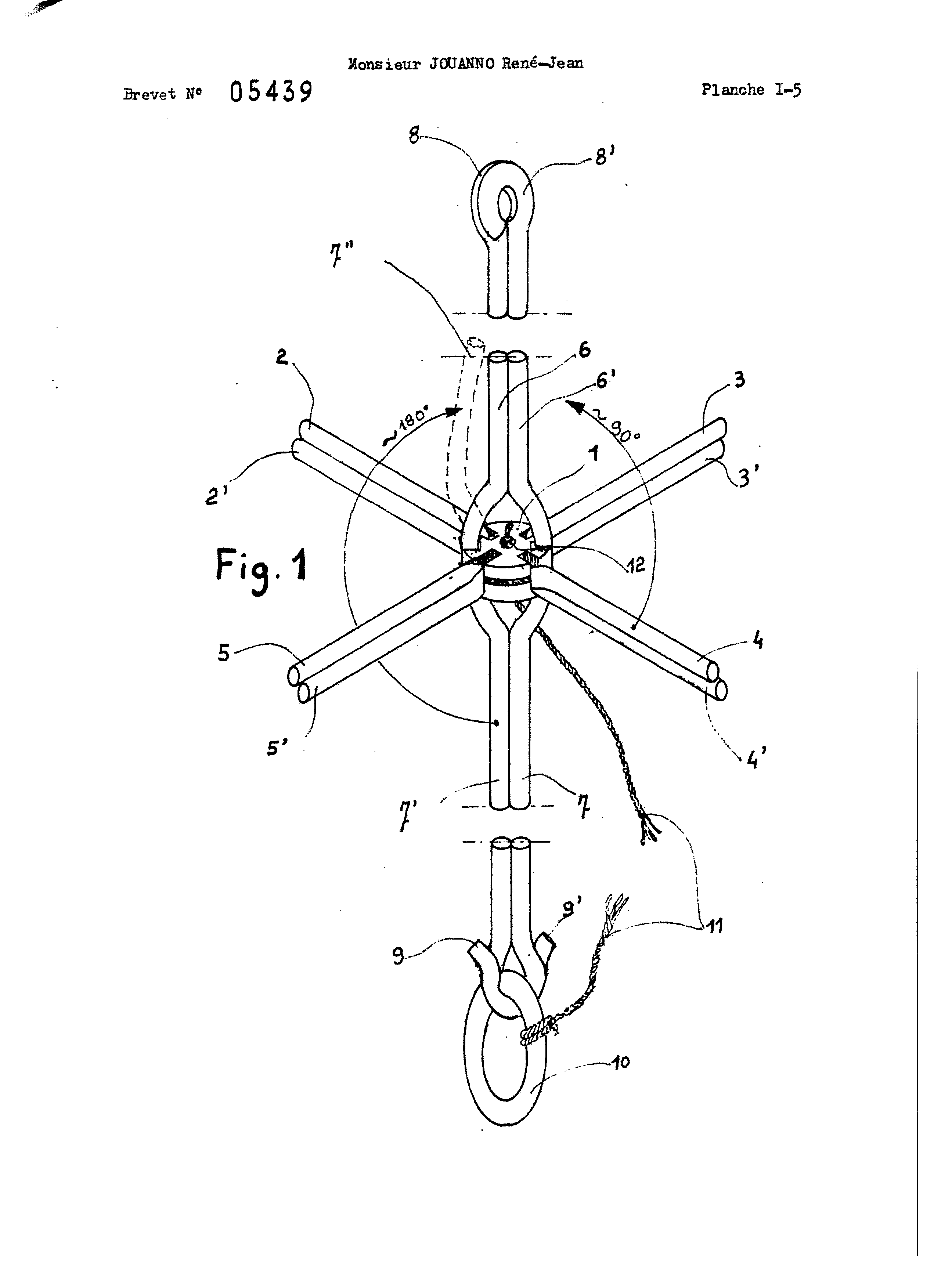
The present invention relates to a radar reflector for use as a target in weather survey. These devices are constituted by a juxtaposition of similar tetrahedrons. Each tetrahedron identical faces comprises, in the shape of isosceles right-angled triangle, orthogonal to each other and made of a reflective material. The fourth face, or base, is not materialized. This juxtaposition of tetrahedrons constitutes a volume whose center point is occupied by all of the apices of all tetrahedra; the latter having two two-a common face. In the present state of the technique, the reflectors may be classified into two categories: " those delivered in parts and mounted for the place and when required by the user. This arrangement, tedious, must necessarily be performed near the location of the pitch and in good conditions of installation; it is impossible to make the darkness or by strong wind. - those which, already assembled during manufacture, have been stored, folded and only have to be deployed and locked to be used. They have the general shape of an umbrella. The complexity of systems currently on the market is such that the weight and the cost of these devices are too high and that, despite their obvious advantages, their use is currently reserved special cases. The reflector, object of the present invention, is of the type "umbrella"; its originality resides in its wing and in the design of an armature lightweight, fully collapsible, which make stiff edges from the common vertex to all tetrahedra constituted by the reflective elements, said armature said canopy rigldifiant * More specifically, the radar reflector folding being of the present invention, of the type consisting of eight of the cube corner adjacent to each other and having a common vertex, the Doe desdite tetrahedrons being not materialized and forming a regular octahedron whose center is said common vertex, is particularly noteworthy in that it includes a sail made before mounting of three squares made of flexible material and reflective, cut to half-diagonal, it is to say according to each line joining the center of the square to one of the corners of said square, and assembled together if level of said half-diagonal to form a spiral, said canopy being maintained tight after deployment of said reflector by a rigid frame * According to mth characteristic OD the inventi n-©, the techniques, reinforcement is S © ISF=daire a black central hinge " According to another feature of the mth 18indention, said asæsfor CD © © pars to SIS constituted by rods pivoted on the central, parallel when the reflector is folded and © nthogenales two to CTAs when the reflector is deployed Mainly in one embodiment, a packaging protects the th® " folded and the person operating the plex maintains a minimum'd *§© aces in this space, the opening of the reflector is controlled by tractirn on U.S.. confectioneries ringO opening " PI-ading® the tearing of the sheath and leaves e8 develop the reflector® With this particular device, in enabling the reflector does request - between when it is still in the package. and the time when it may be dropped - that the m time very smiled§further, this operation can be carried out under all conditions. Other advantages and features of b * shall become apparent better upon reading the description which will follow, made facing of Figures data indicative titrated to the least and limiting, among which O figure 1 schematically shows - the armature of the reflector with a first type of central, figure 2 - shows an example of wrapping of the canopy hovering around the armature of Figure 1, ® figure 3 - is a detail of Figure 2, figure 4 - represents one of three squares constituting the voilursgrams figure 5 - is a sectional view taken along line a-a of Figure 4 when the three squares are assembled according to the present invention® - figure figure 7 - illustrates the reflector partially deployed, *=" Figure 8 represents the reflector fully deployed, Figures 9 and 10 degrees provide an alternate mounting of the sail, - Figure 11 illustrates * another type of useful middle, - figure 12 represents the nut of Figure 11, in the position which it has when the reflector is deployed, and Figure 13=. represents the reflector, provided with the nuts of Figures 11 and 12, partially deployed. Mainly in Figure 1 dedicated to the armature, the central 1 receives the six branches 1' frame s at each branch consists of two rods in the use position of the reflector, all © AE rattling are orthogonal, while in the folded position, they are grouped and substantially parallel to the upper limb made rods® In the embodiment described herein, this upper limb is fixed, while the four horizontal branches, respectively - 5 centeredly constituted by the rods and 2 * 2, * 3 and 3" 4 and 4', 5 and 5,: are hinged at the 1 upward and could describe a circular arc substantially equal to 90 * for the carrying parallel to the upper arm, it is to say to the rods Without the embodiment chosen for example, the fixed shafts Similarly, the rods 7 and 7 *, in their lower part, are machined shaped crooks εf 9 * 9•these hook members are locked with the ring 10 connected to the nut 1 by the tether 11 using a node 12, or other means. That these crooks are directed toward the center (Figure I) or outward (fig.. 8) does not compromise to this type of lock. Before describing the preparation of the sail, it is necessary to include its principle using Figure 2 which indicates, by numbered arrows on the tape embodying the sails, one of many possible paroours. See that the canopy can be wound around the pins by bending all the quarter of a turn to 90° without ever back in the same place. Figure 3 shows in detail the winding around each of the rods constituting one of the branches. The canopy (Figure 4) is formed in three squares flexible reflective strictly superposed in all their elements, each to each 13, it may be, if it finds useful, forming hole 14 for ii 1I ) - to facilitate the markings during assembly, 2I ) - to allow passage of a ring 15 (fig. 6 *) which connects the two rods of a single branch (except for the lower rods 7 and 7')" At oentre square of each of 16 is provided an opening for passage of the nut 1; during assembly, the rods of the frame to be housed in the half diagonals 17 - 18 - 19 and 20. The half diagonalee 20 have reactors provided they are split and joined two & two spiral (Figure 5) about an axis provided by the superposition of the centers of three squares. Said spiral may also be obtained by cutting said tiles, not just spent half-diagonal, but wears line, right or not, joining the center of each square to one edge thereof. Can also be used in an alternative construction each square mounted separately, but it is constrained to realize the three junctions when mounted on the frame. It is also possible to use twelve angled isosceles triangles each representing one-quarter of one of three squares, but it is necessary to secure the connection in all diagonals on each of the twelve rods. Of Be same, without departing from the scope of the invention, it may be interesting to reinforce the corners of the squares of the wing for capping the IO end horizontal rods, for example, and reinforce the central hole optionally; by providing this reinforcement guides for facilitating the positioning of the rods. Figure 7 shows the reflector being deployed} only by matching by a pressure Pi p2 toward the crooks 9 and 9' (the angle The locking of the two crooks is effected by introducing the ring 10 as represented in Figure 1. Figure 8 illustrates the reflector fully deployed and tensioned} fear the simplification of the drawing; the bored 14, as well as the hinge rods in the DUT I-, have not been represented in Figure 8. Alternatively mounting the canopy appears in Figures 9 and 10, using each frame leg does each having the ' a single rod 21; the blade in this case is to be scored in the manner of a hinge on each of its diagonals. Other variations are also possible within the reflector; thus than at the center where the articulate the various branches, it is preferable to use that the walnut pîutêt 1 made of rigid parts, the nuts which can now be described and which, by virtue of a particular shape, allows by bending at certain points, pass from the folded to the unfolded form, without using rigid pivot axes * According to Figure 11, the nut 22 is made of a cross-shaped web; at the top, it has in its center, a block 23 pierced by a pair of vertical blind holes, the rod-receiving vertical upper * without the example selected, this block is traversed by two small holes extending vertically as well 24 for passage of the cable 25. 1 Adjacent to1 central block of square base plate 23 and connected thereto by the web hinge 26 are four other blocks 27 each having a pair of blind bored for receiving the rods of the horizontal branches of 1' frame, after being folded 90° of each web portion connecting to said central block 23" on either side of one of the branches of the oroiz are located two half-Bloos v Bouyer 28 connected thereto by the web hinge 29; these half-blocks 28, having each of its stem, constitute 25 Slid onto the cable, 22 symmetrically to the} two end pieces 31 and 32 having double thus each two blind holes for securing the vertical rods: the top cap 31 is delivered mounted on the end of the upper vertical rod; the lower end cap 32 is installed by the user. On the upper end of the tether is fixed, in this embodiment, a triangular eye 33 for the suspension of the reflector; on the lower end EE even line 25 is attached a ring 34 for the commissioning of the refleotor. It also serves & keying of the radio probe under the reflector. Figure 12 represents the nut 22 deformed, and it is when the reflector is in a fully expanded thereby having six pairs of orthogonal holes. Figure 13 represents 1' apparatus deployed, but not yet tightened; i. by touching the two corners of the lower wing, materialized by the rods 35 and 36 to be stretched the entire reflector; a user puts together the lower rods 35 and 36 using the dual nozzle 32 by sliding it upwards onto the cable 25: the reflector is then ready for use. In one ' ^ érticulier embodiment, the bent reflector is delivered in a sheath, for example plastic, easily tearable, grSce tethers to 11 or 25 by pulling on the loops 10 and 24" A radar reflector is made from six ribs which may be formed from six pairs of rods hinged to a central hub so that when unfolded the ribs are mutually orthogonal. The reflecting surface comprises three squares of reflecting material interconnected along lines cut from the center of each square to an edge portion thereof so as to form a helix. 1 * - Disclosed TMs reflector yadar fold, type ' consisting of eight of the cube corner adjacent each had poked and having an apex coQnnm} the Doe said tetrahedron the n * not materialized and forming a regular octahedron whose center is said common vertex, characterized in that it includes a sail made before mounting of three squares made of flexible material and reflective, cut or link as a half-diagonal, it is to say according to a line joining the center of the square to one of the corners of said square, or any line, right or not, joining the center of the square to an edge thereof, and joined to each other at said half-diagonals, or lines, to form a spiral, said canopy being maintained tight after deployment of said reflector by a rigid reinforcement|reflector comprises specially the characteristics enunciated in LEA-following paragraphs, together or separately0 3e - means is provided for securing the joint of the two rods constituting each branch, thereby stiffening the latter, recesses being provided for this purpose in the diagonal squares constituting the airfoil * 4* - The center is designed such that four pairs of rods are rotatable through an angle of 90°j while the shanks are separately movable 180I , all rods being parallel to the top rods AE location when the reflector is folded * 5 * - The central nut is made of flexible plastic material, cross-shaped, each branch comprising a pivot block 90° relative to the central block about a hinge formed by the plastics material web, two half-blocks being further provided adjacent to two opposite blocks, said half-blocks pivoting of 90I with respect to the blocks by the hinge * 6* - The nut comprises a stop located below the central block and restricting the pivot blocks and half blocks * 7 * - The lower rods are provided at their end of the crossover which cooperate with a loop while maintaining them in closed position, thereby tensioning the canopy of the reflector and thus locking the latter * 8 * - A tip is provided, - with two holes for receiving the lower ends of the rods, thereby locking the reflector * Each connected of the armature consists of a single rod, . the sail being then scored in the manner of a hinge. 10. - The reflector is provided with a ring for its suspension and a ring attached to the central noil by a rope for hooking to said reflector, a radio probe*