Method for detecting deterioration defect of structural part
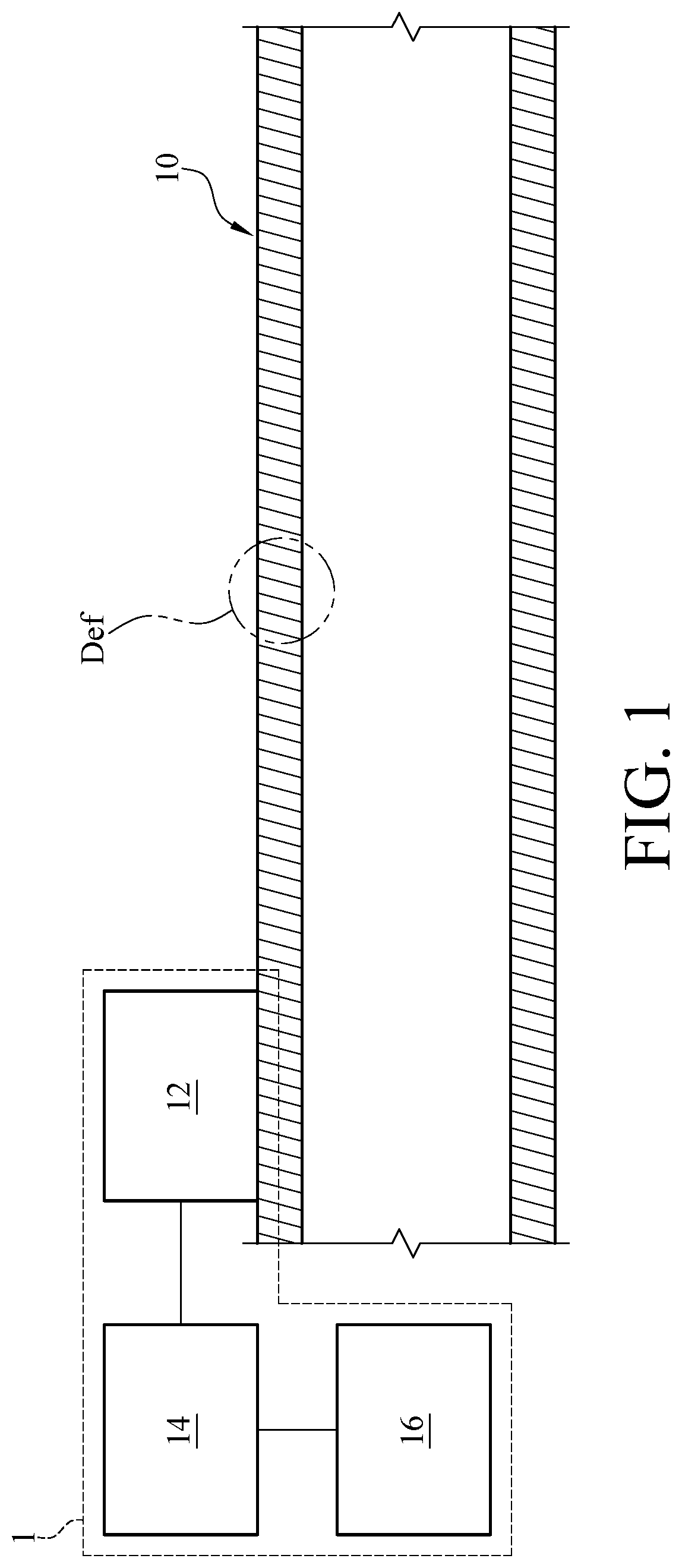
This non-provisional application claims priority under 35 U.S.C. § 119(a) on Patent Application No(s). 106140912 filed in Taiwan, R.O.C. on Nov. 24, 2017, claims priority under 35 U.S.C. § 119(e) on Provisional Application No(s). 62/532,924 filed in U.S. on Jul. 14, 2017, the entire contents of which are hereby incorporated by reference. The disclosure relates to method for detecting a deterioration defect of a structural part. Recently, the frequency of occurrence of accidents involving domestic industrial pipelines increases. When industrial pipelines leak due to abnormalities, it leads to serious disasters, such as casualties and property damage. The main cause of anomalies in industrial pipelines is human-induced factors, and secondly material deterioration in pipelines or equipment. In order to avoid such disasters, full-time monitoring of industrial pipelines is considered as a priority. Although manufacturers of various countries have developed a monitoring system in this regard, the concept of the monitoring system is based on a monitoring of process parameters, an analysis of operating status and performance and still lacks the capabilities of detecting deterioration. In other words, this type of monitoring system only detects when the pipeline is damaged and leaks, and fails to meet the demands of the safety operation of factories and the reduction of risks. The main technical shortcomings of the present industrial pipeline safety monitoring are summarized as follows. First, the environmental sensors or process parameters sensors set up at the site are used for the process monitoring to regulate the production process, and it lacks appropriate safety diagnosis modules for the logical judgment analysis. Second, it lacks the monitoring technology of sensing deterioration remotely, and commonly used non-destructive detection technology is only applicable to the position of partial pipeline where the sensors are disposed. This type of detection technology can only be used for detecting when the pipeline is broken and fluid leaks, and it is impossible to send out an early warning signal in the event of deterioration. Third, the operating environment of industrial plants varies with the system, structure and components. The sensors must have the durability to overcome the problems of high temperature and high humidity environment as well as long-term monitoring. In other words, it is not easy to instantaneously detect damage or deterioration of the pipeline due to the limitations of the conventional pipeline inspection methods and technique. Accordingly, the proper time for immediately performing maintenance and dealing with contingency is missed. Therefore, in the field of industrial safety, it is necessary to develop technologies related to diagnosis and monitoring so as to establish a complete monitoring system for the issue of pipeline safety. A method for detecting deterioration defect of a structural part is disclosed according to one embodiment of the present disclosure. The method includes the following steps: detecting a waveform of time domain of the structural part by a sensor disposed on the structural part; performing a conversion of time domain to frequency domain for the waveform of time domain by a processor electrically connected to the sensor so as to obtain an actual modal parameter of each of a plurality of modals related to a waveform of frequency domain of the structural part; comparing the actual modal parameter of each of the plurality of modals to modal parameter information stored in a database to determine whether a deterioration defect exists in the structural part; and determining a degree and a position of the deterioration defect when the deterioration defect exists in the structural part; wherein the modal parameter information comprises sets of comparison modal parameters, and each of the sets of comparison modal parameters indicates a respective one of the deterioration defect of the position and other deterioration defects of other positions in the structural part. The present disclosure will become more fully understood from the detailed description given hereinbelow and the accompanying drawings which are given by way of illustration only and thus are not limitative of the present disclosure and wherein: In the following detailed description, for purposes of explanation, numerous specific details are set forth in order to provide a thorough understanding of the disclosed embodiments. It will be apparent, however, that one or more embodiments may be practiced without these specific details. In other instances, well-known structures and devices are schematically shown in order to simplify the drawings. Please refer to Please further refer to Then, in step S205, the processor 14 compares the actual modal parameter of each of the plurality of modals M1-M5 to modal parameter information stored in the database 16 to determine whether a deterioration defect exists in the structural part 10, such as the deterioration defect Def shown in Please refer to The modal M1 is illustrated as an example in the following paragraph. When the processor 14 obtains the amplitude value V1 of the characteristic frequency f1 of the modal M1, the processor 14 is capable of finding out a respective first deterioration curve among the plurality of first deterioration curves included in the comparison modal parameters MA1 among the sets of comparison modal parameters stored in the database 16, as shown in The system for detecting deterioration defect 1 is not capable of obtaining the first deterioration curve of the structural part 10 through the amplitude value due to the limitation of the disposing position of the sensor 12 on the structural part 10 when using the amplitude value of the characteristic frequency shown in The aforementioned embodiment of The embodiment of In this embodiment, assume that the modals M1 and M2 of the structural part 10 obtained by the processor 14 respectively correspond to the set of comparison modal parameters MF1 and MF2 stored in the database 16, and the actual modal parameter of the modal M1 and the actual modal parameter of the modal M2 respectively includes the characteristic frequency f1 and the characteristic frequency f2. The processor 14 searches for possible degree and position of the deterioration defect of the structural part 10 according to the characteristic frequency f1 and the second deterioration curves P1-P16 included in the set of comparison modal parameters MF1 stored in the database 16. As shown in More specifically, in one embodiment, the step that the processor 14 determines the degree and the position of the deterioration defect according to the at least two sets of predicted deterioration defect parameters includes filtering out at least one predicted deterioration defect parameter repeated by comparing the at least two sets of predicted deterioration defect parameters, and the at least one predicted deterioration defect parameter is related to the degree and the position of the deterioration defect. In this embodiment, the processor 14 filters out the predicted deterioration defect parameters repeated, which are predicted deterioration defect parameters DQ1-DQ3, by comparing the set of predicted deterioration defect parameters DP1-DP8 and the set of predicted deterioration defect parameters DQ1-DQ3. Thereby, the processor 14 determines that the degree and the position of the deterioration defect of the structural part 10 are respectively the degree and the position of the deterioration defect corresponding to one of the predicted deterioration defect parameters DQ1-DQ3. In practice, in order to determine the degree and the position of the deterioration defect more accurately, the processor 14 obtains a set of predicted deterioration defect parameters other than the above two sets of predicted deterioration defect parameters further according to a characteristic frequency included in an actual modal parameter of a modal other than the aforementioned modal M1 and M2, as well as a set of comparison modal parameters other than the aforementioned set of comparison modal parameters MF1 and MF2. Then, the processor 14 further compares the set of predicted deterioration defect parameters to the above two sets of predicted deterioration defect parameters to filter out at least one predicted deterioration defect parameter repeated. In other words, the more characteristic frequencies of modals the processor 14 obtains, the more accurately the processor 14 is capable of determining the degree and the position of the deterioration defect of the structural part 10. In one embodiment, the comparison modal parameter MF1 and MF2 are obtained in their own respective time. For example, the comparison modal parameter MF1 is obtained in a first time, and the comparison modal parameter MF2 is obtained in a second time. The embodiments of The technical ideas of the system and the method for detecting the deterioration defect of the structural part of the present disclosure are adapted to a variety of structural parts with different forms. For example, please refer to In the embodiment of In the embodiment of In the embodiment of In one embodiment, the actual modal parameter of each modal includes a characteristic frequency, and the characteristic frequency has a first frequency in a first direction and a second frequency in a second direction. The method for detecting the deterioration defect further includes determining a form of the deterioration defect according to the first frequency in the first direction and the second frequency in the second direction. Specifically, in this embodiment, the sensor 12 of the present disclosure is a three-axis accelerometer sensor used for detecting frequencies in a variety of directions, such as the frequency in the X axis direction and the frequency in the Y axis direction. The processor 14 determines the form of the deterioration defect of structural part 10 according to the variation of the frequency in the X axis direction and the variation of the frequency in the Y axis direction. The form of deterioration defect is, for example, a uniform defect or a partial defect. In detailed, in one embodiment, the step of determining the form of the deterioration defect according to the first frequency in the first direction and the second frequency in the second direction by the processor 14 includes the step of determining whether the first frequency in the first direction is consistent with the second frequency in the second direction. The form of the deterioration defect is determined as a uniform defect by the processor 14 when the first frequency in the first direction is consistent with the second frequency in the second direction. The form of the deterioration defect is determined as a partial defect by the processor 14 when the first frequency in the first direction is not consistent with the second frequency in the second direction. In one embodiment, the database 16 is a partial-defect database or a uniform-defect database, and the method for detecting deterioration defect of the structural part 10 further includes determining whether the database 16 is the partial-defect database or the uniform-defect database according to the form of the deterioration defect. More specifically, in a practical example, in the method for detecting the deterioration defect of the structural part, the processor 14 determines the form of the deterioration defect according to a first frequency in a first direction and a second frequency in a second direction. When the deterioration defect of the structural part 10 is determined as a partial defect, the database 16 is considered as a partial-defect database. Contrarily, when the deterioration defect of the structural part 10 is determined as a uniform defect, the database 16 is considered as a uniform-defect database. The processor 14 performs the detection for the degree and the position of the deterioration defect based on Based on the above description, in the system and the method for detecting the deterioration defect disclosed in the present disclosure, measurements are detected by the sensor and further analyzed based on time domain signals and frequency domain signals, accompanying with the utilization of the database related to the deterioration defect of the structural part, so as to provide information of the real-time monitoring and the warning in advanced for avoiding accidents of structural parts such as industrial pipelines or industrial tanks. Moreover, the system and the method for detecting the deterioration defect disclosed in the present disclosure are further applicable with the wireless transmission technology across devices to build an industrial safety monitoring platform and provide a high-performance and safe remote monitoring service. A method for detecting deterioration of a structural part includes: detecting a waveform of time domain of the structural part by a sensor disposed on the structural part; performing a conversion of time domain to frequency domain for the waveform of time domain by a processor electrically connected to the sensor so as to obtain an actual modal parameter of each of a plurality of modals related to a waveform of frequency domain of the structural part; comparing the actual modal parameter of each of the plurality of modals to modal parameter information stored in a database to determine whether a deterioration defect exists in the structural part; and determining a degree and a position of the deterioration defect when the deterioration defect exists in the structural part. 1. A method for detecting deterioration defect of a structural part, comprising:
detecting a waveform of time domain of the structural part by a sensor disposed on the structural part; performing a conversion of time domain to frequency domain for the waveform of time domain by a processor electrically connected to the sensor so as to obtain an actual modal parameter of each of a plurality of modals related to a waveform of frequency domain of the structural part; comparing the actual modal parameter of each of the plurality of modals to modal parameter information stored in a database to determine whether a deterioration defect exists in the structural part; and determining a degree and a position of the deterioration defect when the deterioration defect exists in the structural part; wherein the modal parameter information comprises sets of comparison modal parameters, and each of the sets of comparison modal parameters indicates a respective one of the deterioration defect of the position and other deterioration defects of other positions in the structural part. 2. The method for detecting deterioration defect of the structural part according to wherein each of the plurality of first deterioration curves corresponds to a predicted deterioration defect having a deterioration defect value and located in a position of the structural part. 3. The method for detecting deterioration defect of the structural part according to obtaining at least two sets of predicted deterioration defect parameters according to the characteristic frequencies of the plurality of modals and the plurality of second deterioration curves comprised in the sets of comparison modal parameters; and determining the degree and the position of the deterioration defect according to the at least two sets of predicted deterioration defect parameters. 4. The method for detecting deterioration defect of the structural part according to filtering out at least one predicted deterioration defect parameter repeated by comparing the at least two sets of predicted deterioration defect parameters; wherein the at least one predicted deterioration defect parameter is related to the degree and the position of the deterioration defect. 5. The method for detecting deterioration defect of the structural part according to determining a disposing position of the sensor on the structural part according to a characteristic frequency of each of the sets of comparison modal parameters of the database. 6. The method for detecting deterioration defect of the structural part according to 7. The method for detecting deterioration defect of the structural part according to 8. The method for detecting deterioration defect of the structural part according to determining whether the first frequency in the first direction is consistent with the second frequency in the second direction; determining the form of the deterioration defect as an uniform defect when the first frequency in the first direction is consistent with the second frequency in the second direction; and determining the form of the deterioration defect as an partial defect when the first frequency in the first direction is not consistent with the second frequency in the second direction. 9. The method for detecting deterioration defect of the structural part according to 10. The method for detecting deterioration defect of the structural part according to CROSS-REFERENCE TO RELATED APPLICATIONS
TECHNICAL FIELD
BACKGROUND
SUMMARY
BRIEF DESCRIPTION OF THE DRAWINGS
DETAILED DESCRIPTION
0% 22.05239 60.7595 119.0305 196.5821 293.3228 25% 21.67752 58.70199 116.0998 195.5517 292.006 50% 20.77782 54.38835 111.2858 193.6701 289.0152 75% 18.47006 47.43438 105.8418 190.2872 282.3232 0% 22.05239 60.7595 119.0305 196.5821 293.3228 25% 21.08352 60.7286 116.2668 196.3019 287.4922 50% 18.96757 60.63222 111.1252 195.4105 279.0904 75% 15.04959 60.32965 104.5329 192.6023 271.1687 0% 107.6097 299.3441 576.457 912.6012 1229.042 25% 107.0839 296.2418 571.8002 908.6208 1227.168 50% 105.9831 289.5574 561.6209 900.6288 1222.553 75% 102.8482 272.4134 538.6506 881.1895 1208.208 0% 107.6097 299.3441 576.457 912.6012 1229.042 25% 105.8333 295.0557 574.2221 910.5367 1222.309 50% 102.1406 283.489 567.4657 905.5377 1212.337 75% 92.93562 264.4272 549.8736 889.8458 1207.469 0% 79.61369 217.4225 420.4544 682.7447 998.1407 25% 78.88281 214.2276 416.3346 680.6828 995.8001 50% 77.32048 206.8515 407.3621 675.946 989.165 75% 72.86193 189.1832 389.8823 624.6216 968.927 0% 79.61369 217.4225 420.4544 682.7447 998.1407 25% 78.00208 217.2905 417.5578 679.9839 993.1377 50% 74.25027 216.9309 409.6331 646.52 981.6498 75% 64.82471 215.732 391.9877 565.5287 960.5893 0% 219.8807 561.3934 1001.138 1492.311 2007.315 25% 219.0764 557.3356 995.5444 1490.648 2006.844 50% 217.4524 549.2907 984.642 1486.917 2003.783 75% 211.2352 536.2614 967.8168 1481.157 1997.218 0% 219.8807 561.3934 1001.138 1492.311 2007.315 25% 217.679 561.4051 996.8888 1492.386 2000.988 50% 210.4497 561.2004 987.3976 1491.165 1990.76 75% 199.0602 560.656 970.7511 1488.125 1978.935


CPC - классификация
FF1F17F17DF17D5F17D5/F17D5/0F17D5/06GG0G01G01MG01M3G01M3/G01M3/2G01M3/28G01M3/280G01M3/2807G01M5G01M5/G01M5/0G01M5/00G01M5/002G01M5/0025G01M5/003G01M5/0033G01M5/006G01M5/0066G01NG01N2G01N22G01N229G01N2291G01N2291/G01N2291/0G01N2291/01G01N2291/015G01N2291/02G01N2291/023G01N2291/025G01N2291/0258G01N29G01N29/G01N29/0G01N29/04G01N29/048G01N29/1G01N29/11G01N29/4G01N29/44G01N29/442G01N29/4427G01N29/444G01N29/4445G01N29/46Цитирование НПИ
702/38702/39
73/592
TW Office Action dated Jun. 19, 2018 as received in Application No. 106140912.
TW Office Action in application No. 107107654 dated Apr. 12, 2019.
TW Office Action in application No. 107107654 dated Dec. 28, 2018.
“Artificial Neural Network for the Classification of Steel Hollow pipe”, N mohamad, Hafizawati, R.A Siregar, M. Hariharan and Fauziah Mat, Proceedings of International Conference on Applications and Design in Mechanical Engineering (ICADME), Oct. 11-13, 2009.
“Detection of pipe wall-thinning based on change of natural frequencies of shell vibration modes”, Soonwoo Han , Jinho Park , To Kang, 19thWorld Conference on Non-Destructive Testing 2016, Jul. 2016.
“Frequency-based experimental and theoretical identification of multiple cracks in straight pipes filled with fluid”, S.M. Murigendrappa, S.K. Maiti, H.R. Srirangarajan, NDT&E International 37 (Feb. 20, 2004) 431-438.
“Identification of wall-thinning and cracks in pipes utilizing vibration modes and wavelets”, M. El-Gebeily ,Y.A. Khulief, Applied Mathematical Modelling 40 (Dec. 14, 2015) 5335-5348.
“Inexpensive Pipelines Health Evaluation Techniques Based on Resonance Determination”, Numerical Simulation and Experimental Testing, Waheed Sami Abushanab, Engineering, Mar. 27, 2013, 5, 337-343.