Contact element
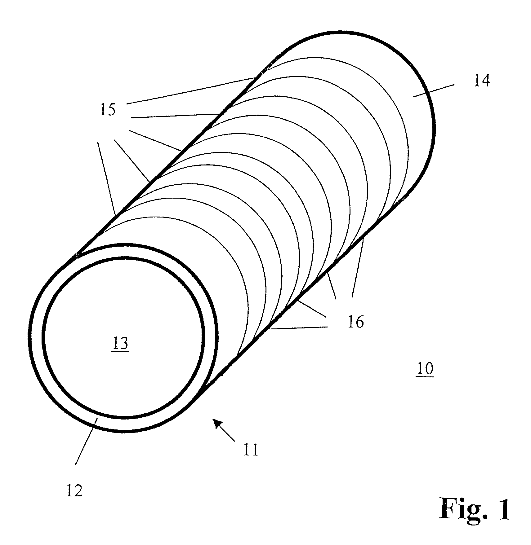
[0001] The invention relates to the design of non-aging contact elements that form a conductive connection between two opposing contacts in the compressed state. [0002] Contact elements corresponding to the generic term in claim 1 are known to the technician and have been used in large quantities to form conductive connections for a long time. [0003] These contact elements, also referred to using the term “conductive rubber”, generally have a rectangular body on the surface of which there are a number of conductors. The body is formed entirely from a foamed or vulcanized plastic to ensure that the body can be elastically deformed when force is applied. [0004] If on a circuit board a row of contacts having a number of contacts located next to each other is to be electrically connected to a row of contacts of a component, for example, then the contact element is first placed on the row of contacts on the circuit board, whereby the conductors on the contact element make contact with the contacts on the circuit board. Then the component with its row of contacts is placed on the contact element so that its contacts make physical contact with the conductors of the contact element. In order to ensure a certain durability of the contact produced in this manner, the height of the contact element when it is in its original state is reduced. This can be done, for example, by lightly pressing the component against the circuit board after it has been placed on the contact element and securing it in this state. If this state is reached and the contact element is clamped between the rows of contacts on the circuit board and component, then the restoring force with which the contact element attempts to assume its height and form when in its original state causes the conductors of the contact element to be pressed against the rows of contacts on the circuit board and component. To achieve the required elasticity and/or ability to store energy, the known contact elements and/or the material used for the body generally have very low expansion energy coefficients. This coefficient is the product of the tensile strength and the fracture elongation. When silicone rubber, which has a tensile strength of approximately 0.49 N/mm2and a fracture elongation of 200%, is used as the body material, then the value of this coefficient, which specifies the ability to store energy, is 98. [0005] Even though this type of contact quick and easy to make, it turns out that such electrical connections only have a limited long-term stability. In particular, it has been determined that the conductive connections made using the contact elements described above do not guarantee a secure contact anymore when subject to environmental influences and variable climatic conditions. Possible reasons for this are that the material may harden and structural changes may arise due to the conditions and influences mentioned. [0006] That is why the invention is the result of the task of specifying a contact element that possesses the necessary long-term stability while still making it quick and easy to connect rows of contacts. [0007] This task is accomplished using the features specified in claim 1. Advantageous extensions and expansions of the invention can be obtained in claims 2 through 5. A method for manufacturing a contact element is specified in claim 6. The features according to claim 7 have a different design that also accomplishes the task. [0008] If the body 11 is formed only by a thin wall that does not necessary completely encircle the hollow space 13 enclosed by the body, then it is ensured that the required elasticity of the body is determined primarily by the thickness of the wall and the three-dimensional shape of the body. However, this does not mean that the properties of the material from which the body or wall is made are entirely insignificant. In contrast to the background of the invention, the material from which the walls are made must have the ability to store a large quantity of deformation energy per unit of volume to ensure that sufficient spring force or clamping force is provided in view of the necessary path of deformation in spite of the fact that the elasticity of the body is determined by the relatively thin wall. According to the experiences of the applicant, the “block” design of the contact elements according to the background of the invention and the material properties needed to produce the required elasticity are responsible for the fact that the contact elements manufactured in this manner have only a limited long-term stability. In more precise terms, the lack of long-term stability of the known contact elements can be attributed to the fact that the material used is subject to shrinkage, amongst other things. If, for example, a foamed material is used for the elastic body, gas bubbles embedded in the body diffuse into the environment after a while, thereby reducing the original spatial dimensions of the contact element at the same time. This shrinkage is responsible for the fact that the force with which a contact element clamped between a circuit board and a component is pressed against the rows of contacts on the component and circuit board is reduced or that the previously existing contact is broken. [0009] However, if in accordance with the invention the body of the contact element is formed only by a thin wall and the required elasticity is achieved through the three-dimensional shape and thickness of the wall, then materials used in “block” designs that also display elasticity do not have to be used, thereby simultaneously reducing or completely eliminating the shrinkage problem. If one uses thin-walled optical fiber or an optical fiber composite material, for example, whereby the overall elastic properties are primarily due to the optical fiber, then neither slow reorientation of the structure of the material nor chemically induced material changes can arise because glass as a material is resistant to these effects. Another surprising result in this context is that materials can be used whose expansion energy coefficients are significantly higher than the values stated in the background of the invention. In order to clarify this here we would like to point out that coefficients greater than 2800 result when fiberoptic materials are used that have tensile strengths greater than 2400 N/mm2and a fracture elongations of about 1.2%. [0010] As stated in claim 2, there are no restrictions placed on the design of the walls. In addition to the solid design of the wall, the use of braided materials is particularly advantageous when the flexural elasticity resulting from a solid design is to be further increased, for example. [0011] There are also no major restrictions when selecting the type of material, as stated in claim 3, as long as the material used has a certain flexural elasticity. [0012] If in accordance with claim 4 an intermediate layer is used between wall and conductors, then this layer may smooth out any irregularities existing on the surface of the wall or on the surfaces of the conductors. The intermediate layer can also be used as all electrical insulator in addition to its smoothing function when the wall is made of a nonconductive material. [0013] There is a defined contact surface, and therefore a defined contact resistance, when there are tabs on the two opposing areas of the wall that exist to establish contact between the corresponding rows of contacts and that are farther from the center point of the body than the areas of the wall 12 directly adjacent to the tabs. [0014] An especially simple method of manufacturing a contact element equipped with an intermediate layer results when the intermediate layer is designed as a tube and the wall of the body does not completely encircle the hollow space enclosed by the body. In this case it is possible to insert the compressed body into the tube. If the body has reached its end position in the tube and the force that compressed the body is removed, then the body will press against the inside of the tube and put pressure on it. It does not matter in this regard if the conductors are placed on the tube before or after connecting it to the body. [0015] If the contact element is designed corresponding to the features in claim 7, then the same advantages already explained in the context of claim 1 exist because regardless of the material of the body, only the inserts can permanently provide the required spring force or clamping force in view of the required path of deformation due to their ability to store a large quantity of deformation energy per unit of volume. [0016] The following figures contain the following: [0017] [0018] [0019] [0020] [0021] [0022] [0023] [0024] [0025] The invention will now be explained in more detail based on the figures. [0026] [0027] The contact element 10 shown in [0028] [0029] Because, in accordance with the invention, the restoring force primarily responsible for the durability of such electrical connections depends less on the material used due to the use of mostly hollow contact elements 10, a number of materials not usually used for this purpose can be utilized to form the contact elements 10. This does not mean, however, that material properties are to be completely ignored. On the contrary, it must also be insured according to the invention that the material or materials used to form the hollow contact elements 10 are elastic and can be deformed as explained in the context of [0030] Even though the wall 12 in the example according to [0031] The wall 12 does not necessarily have to be solid. Good results were also obtained with walls 12 formed from a braid of plastic, metal or fiberoptic material. If the wall 12 is formed as a braid, then the intermediate layer 20 will also provide a smoothing effect to smooth out the natural irregularities found in the surface structure, in addition to its possible insulating effect. [0032] The contact element 10 shown in [0033] [0034] The contact element 10 shown in [0035] In addition there are two tabs 21 shown in [0036] For the sake of completeness, we would like to point out that the tabs 21 are not limited to contact elements 10 with elliptical cross-sections but can also be formed on contact elements according to [0037] [0038] [0039] [0040] Just for the sake of completeness we would like to point out that the contact elements 10 shown in The invention relates to the design of non-aging contact elements 10 that establish a conductive connection between two opposing contacts in the compressed state. Contact elements 10 according to the background of the invention are generally rectangular, on the surface of which there are a number of conductors 15. As the bodies 11 of such contact elements 10 are made of foamed or vulcanized plastic to provide elasticity, they are subject to aging and therefore cannot ensure a permanent connection. For this reason a contact element 10 is specified according to the invention whose body 11 is formed only by a thin wall 12 that does not necessarily completely encircle a hollow space 13 enclosed by the body 11. This guarantees long-term stability, especially when the wall 12 is made of metal or a fiberoptic material. The same results can then be achieved when the body 11 is equipped with thin inserts 22 made of metal or optical fiber. 1. Contact element
with a body 11 and with a number of electrically conductive conductors 15 that are isolated from each other and arranged on the outer surface 14 of the body 11, characterized in that the body 11 is formed only by a thin wall 12 that does not necessary completely encircle the hollow space 13 enclosed by the body 11. 2. Contact element according to the wall 12 is solid or formed from a braided material. 3. Contact element according to the wall 12 and/or the braid is made of metal or an unfoamed plastic, in particular of a fiberoptic material. 4. Contact element according to there is an intermediate layer 20 between the wall 12 and the conductors 15. 5. Contact element according to one of claims 1 through 4 characterized in that
there are tabs 21 formed on two areas opposite from each other on the wall 12 that are farther from the center point of the body 11 than the areas of the wall 12 directly adjacent to the tabs 21. 6. Method of manufacturing a contact element according to the intermediate layer 20 is formed as a tube 20′, the wall 12 of the body 11 does not completely encircle the hollow space 13 it encloses and the wall 12 is to be compressed and inserted in this state into the tube 20′. 7. Contact element
with a body 11 and with a number of electrically conductive conductors 15 that are isolated from each other and arranged on the outer surface 14 of the body 11, characterized in that there is at lease one thin insert 22 located within the body 11, the corresponding insert 22 is solid or made of a braided material and the corresponding inserts 22 are made of metal or an unfoamed plastic, in particular of a fiberoptic material. FIELD OF THE INVENTION
BACKGROUND OF THE INVENTION
SUMMARY OF THE INVENTION
BRIEF DESCRIPTION OF THE DRAWINGS
DETAILED DESCRIPTION OF THE PREFERRED EMBODIMENTS OF THE INVENTION