Code Grouping for Optical Networks
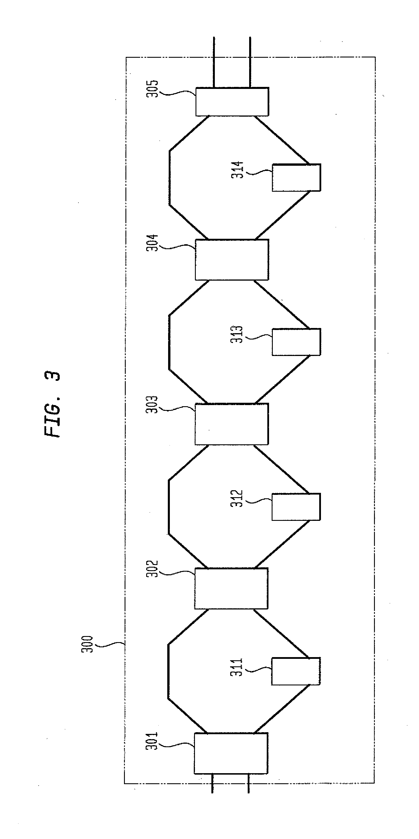
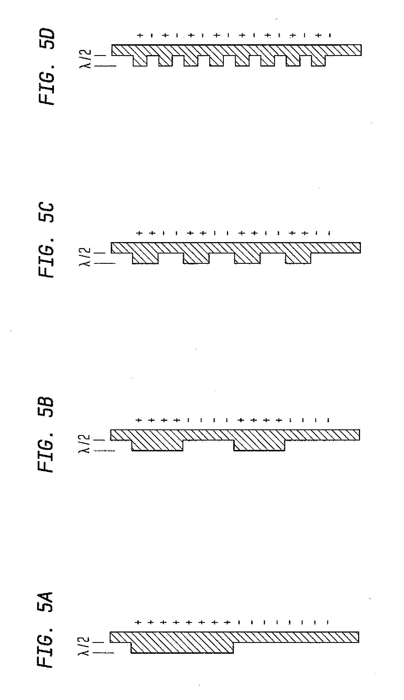
Funding for research was partially provided by the Defense Advanced Research Projects Agency under federal contract MDA972-03-C-0078. The federal government has certain rights in this invention. The present invention relates to optical communication and, more particularly, to routing of groups of spectrally phase encoded optical code division multiple access (OCDMA) signals. Various communications schemes have been used to increase data throughput and to decrease data error rates as well as to generally improve the performance of communications channels. As an example, frequency division multiple access (“FDMA”) employs multiple data streams that are assigned to specific channels disposed at different frequencies of the transmission band. Alternatively, time division multiple access (“TDMA”) uses multiple data streams that are assigned to different timeslots in a single frequency of the transmission band. FDMA and TDMA are quite limited in the number of users and/or the data rates that can be supported for a given transmission band. In many communication architectures, code division multiple access (CDMA) has supplanted FDMA and TDMA. CDMA is a form of spread spectrum communications that enables multiple data streams or channels to share a single transmission band at the same time. The CDMA format is akin to a cocktail party in which multiple pairs of people are conversing with one another at the same time in the same room. Ordinarily, it is very difficult for one party in a conversation to hear the other party if many conversations occur simultaneously. For example, if one pair of speakers is excessively loud, their conversation will drown out the other conversations. Moreover, when different pairs of people are speaking in the same language, the dialogue from one conversation may bleed into other conversations of the same language, causing miscommunication. In general, the cumulative background noise from all the other conversations makes it harder for one party to hear the other party speaking. It is therefore desirable to find a way for everyone to communicate at the same time so that the conversation between each pair, i.e., their “signal”, is clear while the “noise” from the conversations between the other pairs is minimized. The CDMA multiplexing approach is well known and is explained in detail, e.g., in the text “CDMA: Principles of Spread Spectrum Communication,” by Andrew Viterbi, published in 1995 by Addison-Wesley. Basically, in CDMA, the bandwidth of the data to be transmitted (user data) is much less than the bandwidth of the transmission band. Unique “pseudonoise” keys are assigned to each channel in a CDMA transmission band. The pseudonoise keys are selected to mimic Gaussian noise (e.g., “white noise”) and are also chosen to be maximal length sequences in order to reduce interference from other users/channels. One pseudonoise key is used to modulate the user data for a given channel. This modulation is equivalent to assigning a different language to each pair of speakers at a party. During modulation, the user data is “spread” across the bandwidth of the CDMA band. That is, all of the channels are transmitted at the same time in the same frequency band. This is equivalent to all of the pairs of partygoers speaking at the same time and in the same frequency band. The introduction of noise and interference from other users during transmission is inevitable (collectively referred to as “noise”). Due to the nature of the pseudonoise key, the noise is greatly reduced during demodulation relative to the user's signal because when a receiver demodulates a selected channel, the data in that channel is “despread” while the noise is not “despread.” Thus, the data is returned to approximately the size of its original bandwidth, while the noise remains spread over the much larger transmission band. The power control for each user can also help to reduce noise from other users. Power control is equivalent to lowering the volume of a loud pair of partygoers. CDMA has been used commercially in wireless telephone (“cellular”) and in other communications systems. Such cellular systems typically operate at between 800 MHz and 2 GHz, though the individual frequency bands may only be a few MHz wide. An attractive feature of cellular CDMA is the absence of any hard limit to the number of users in a given bandwidth, unlike FDMA and TDMA. The increased number of users in the transmission band merely increases the noise to contend with. However, as a practical matter, there is some threshold at which the “signal-to-noise” ratio becomes unacceptable. This signal-to-noise threshold places real constraints in commercial systems on the number of paying customers and/or data rates that can be supported. CDMA has also been used in optical communications networks. Such optical CDMA (OCDMA) networks generally employ the same general principles as cellular CDMA. However, unlike cellular CDMA, optical CDMA signals are delivered over an optical network. As an example, a plurality of subscriber stations may be interconnected by a central hub with each subscriber station being connected to the hub by a respective bidirectional optical fiber link. Each subscriber station has a transmitter capable of transmitting optical signals, and each station also has a receiver capable of receiving transmitted signals from all of the various transmitters in the network. The optical hub receives optical signals over optical fiber links from each of the transmitters and transmits optical signals over optical fiber links to all of the receivers. An optical pulse is transmitted to a selected one of a plurality of potential receiving stations by coding the pulse in a manner such that it is detectable by the selected receiving station but not by the other receiving stations. Such coding may be accomplished by dividing each pulse into a plurality of intervals known as “chips”. Each chip may have the logic value “1”, as indicated by relatively large radiation intensity, or may have the logic value “0”, as indicated by a relatively small radiation intensity. The chips comprising each pulse are coded with a particular pattern of logic “1”'s and logic “0”'s that is characteristic to the receiving station or stations that are intended to detect the transmission. Each receiving station is provided with optical receiving equipment capable of regenerating an optical pulse when it receives a pattern of chips coded in accordance with its own unique sequence but cannot regenerate the pulse if the pulse is coded with a different sequence or code. Alternatively, the optical network utilizes CDMA that is based on optical frequency domain coding and decoding of ultra-short optical pulses. Each of the transmitters includes an optical source for generating the ultra-short optical pulses. The pulses comprise Fourier components whose phases are coherently related to one another. Each Fourier component is generally referred to as a frequency bin. A “signature” is impressed upon the optical pulses by independently phase shifting the individual Fourier components comprising a given pulse in accordance with a particular code whereby the Fourier components comprising the pulse are each phase shifted a different amount in accordance with the particular code. The encoded pulse is then broadcast to all of or a plurality of the receiving systems in the network. Each receiving system is identified by a unique signature template and detects only the pulses provided with a signature that matches the particular receiving system's template. Recently, there has been a renewed interest in OCDMA due to its potential for offering increased levels of security at ultra-high data rates as well as simplifying key networking functions such as passive all-optical code translation (CT), routing based on code assignment, and physical layer code scrambling. Although OCDMA operates at the physical layer in many ways, the most common form of OCDMA network operates in a broadcast-and-select configuration in which communication is established between matching encoders and decoders as shown in To establish arbitrary connectivity amongst all users, the encoders and/or decoders at the edges of the network must be tunable. However, since these networks operate in a broadcast-and-select mode, tunable decoders make eavesdropping on a given transmission relatively easy. At the same time, tunable encoders with fixed decoders obviate simple multicast operation and make it possible for two transmitters to attempt to send to the same decoder simultaneously, thus resulting in code collision and data loss. The addition of an appropriate CT stage at the midpoint of a conventional OCDMA network can passively route communication between mismatched encoders and decoders as shown in Previously, CT and routing of OCDMA signals focused on dealing with one code at a time. As such, there is a need to assign and label groups using codes such that these groups can be passive routed as a composite entity on the basis of these labels. In an aspect of the invention, an optical network is provided. The optical network includes a transmitting station operable to transmit a group of optical encoded signals, an encoder coupled to the transmitting station operable to label the group of optical signals with a group-specific code, and a receiving station operable to receive the group of optical signals labeled with the group label, the receiving station is operable to read the optical signal if the code used to label the group of optical signals correspond to the transmitting station. In another aspect of the invention, the optical network may also includes a variable coder coupled in between the transmitting and the receiving stations, the variable coder is operable to re-label the incoming optical signal with a new group of codes corresponding to the receiving station. In yet another aspect of the invention, the set of codes used to label the group of optical signals are Walsh-Hadamard codes. In yet another aspect of the invention, the variable coder further comprises a plurality of Walsh-Hadamard coders. In yet another aspect of the invention, the variable coder includes a plurality of switches, and at least one Walsh encoder coupled between a first switch and second switch of the plurality of switches, the first switch being operable to selectively route an optical signal to the Walsh encoder to apply a Hadamard sequence to the optical signal. In yet another aspect of the invention, each switch among the plurality of switches a 2×2 crossbar switch. In yet another aspect of the invention, the variable coder further includes a third switch. In yet another aspect of the invention, the variable coder further includes at least one Walsh encoder coupled between the second switch and the third switch. A more complete appreciation of the subject matter of the present invention and the various advantages thereof can be realized by reference to the following detailed description in which reference is made to the accompanying drawings wherein like reference numbers or characters refer to similar elements. The modulated data stream 125 is then fed to a spectral phase encoder 132. As is discussed in further detail below, the spectral phase encoder 132 applies a phase code associated with a user to each optical pulse in the data stream to produce an encoded data stream 135. The phase code operates to provide a “lock” so that only a corresponding phase decoder with the appropriate “key” or phase conjugate of the phase code of the spectral phase encoder may unlock the encoded data stream. Typically, a spectral phase encoder is associated with a particular user and therefore allows only another user with the appropriate key to decode or receive information from the particular user. The information appears as noise to users that do not have the appropriate key. The encoded data stream 135 may then be synchronously combined with other differently encoded data streams and transported over a network 140, such as Wavelength Division Multiplex (WDM) network for example, to a spectral phase decoder 144 that, preferably, applies the phase conjugate of the phase code of the spectral phase encoder 132, as discussed above. The spectral phase decoder 144 provides a decoded data stream 149 to an optical time gate 150. The spectral phase decoder works in a manner similar to that of the spectral phase encoder as will be described below. The optical time gate 154 operates to reduce multiple access interference by temporally extracting only a desired user channel from among the decoded stream. The optical time gate 154 produces a user data stream 159, which is fed to a data demodulator 164. Where ON/OFF keying was employed at the transmitting end, the data demodulator 164 comprises an amplitude detector that reproduces the digital data stream 124. In accordance with an aspect of the present invention, the laser source 110, data modulator 122 and spectral phase encoder 132 may comprise a transmitting station 170 associated with a user. The spectral phase decoder 144, optical time gate 154 and demodulator 164 may preferably comprise a receiving station 180 associated with a user. The spectral phase encoder may utilize a set of Hadamard codes, which are orthogonal and binary, by breaking each Hadamard code into groups of codes. As an example, any of the Hadamard codes can be broken down into a particular multiplicative sequence of Walsh codes. An example of a multiplicative series of codes that span the set of Hadamard code is the set of Walsh codes. Note that the Walsh codes form a proper subset of the Hadamard codes. It should be noted that many (but not all) other sub-groups of size log2(N) selected from the Hadamard codes also form a multiplicative basis that can span the complete set of Hadamard codes in sense of the equation in below. Any of these spanning groups can be used as the basis for the variable Hadamard coder and we focus here on the Walsh subset for specificity. Because Hadamard codes are truly orthogonal, the system can achieve relatively high spectral efficiency with minimal multi-user interference (MUI). This coding scheme offers orthogonally in the sense that MUI is zero at the time that the decoded signal is maximum. The number of orthogonal codes is equal to the number of frequency bins; hence, relatively high spectral efficiency is possible. Binary Hadamard codes are converted to phase codes by assigning to +1's and −1's phase shifts of 0 and π, respectively. To encode data, which contains a spread of frequencies, as opposed to the unmodulated pulse stream, which contains only the initial comb of frequencies produced by a mode locked laser (MLL), it is preferable to define frequency bins around the center frequencies. Encoding data then consists of applying the phase shift associated with a frequency to the entire bin. The output of the phase encoder is then a signal obtained by summing the phase-shifted frequency components of the modulated signal, or equivalently, by convolving the modulated optical signal at the input of the phase encoder with the inverse Fourier transform of the phase code. Breaking down the Hadamard code into a group of codes allows for the development of an encoder/decoder that can be implemented in relatively small time scales as discussed below. In an aspect of the present invention the spectral phase encoder is implemented as a dynamic coder that is desirably reconfigurable at the microsecond to nanosecond time scales. In addition, the number of adjustable elements required to span a code space of N codes grows as log2(N) rather than as N. The adjustable elements in such coder are not based on λ-scale adjustments of the phase mask, but instead function as optical 2×2 switches arranged in a cascade with fixed Walsh coders. Although optical switching is usually fast enough to operate on the time scale of bits or perhaps packets and with a significant reduction in the number of adjustable elements, the encoder 300 if The spectral phase encoder 300 generally works under the principle that Hadamard codes of order N, Hn, where nε1 . . . n can be decomposed into products of a smaller basis set of Walsh codes Wmof length N where the maximum number of Walsh codes required to reconstruct any of these Hadamard code is log2(N). Walsh codes exist for only certain values of m, specifically for m=2p-1where pε1 . . . log2(N) and m=0. The Walsh codes, like the Hadamard codes, are of length N and all the elements are either +1 or −1. In general, the nthcode Wnof length N is characterized by alternating blocks of +1's and −1's where the length of the blocks is given by n. Thus for order N=16, the Walsh codes are as discussed below. W8consisting of eight +1's followed by eight −1's (+ + + + + + + + − − − − − − − −). W4consisting of two sets of four +1's and four −1's. (+ + + + − − − − + + + + − − − −). W2consisting of four sets of two +1's and two −1's. (+ + − − + + − − + + − − + + − −). W1consisting of eight sets of +1's and −1's. (+ − + − + − + − + − + − + − + −). W0consisting of all 1's (+ + + + + + + + + + + + + + + +). In general, the ithelement of Hadamard code n of order N as the following product of the ithelements of the Walsh codes, also of order N can be written as: where bjis jthdigit of the binary representation of (n−1). As a specific example, any of the 16 codes available in H16can be expressed as a product of W1/W2, W4, and W8(which may correspond to Walsh coders 314, 313, 312, and 311 respectively). The 16 Hadamard codes of order 16 can be represented as: The sum of the Walsh indices equals one less than the corresponding Hadamard code index. Thus the settings for the 2×2 switches (i.e., cross or bar state) to set the coder to Hadamard code n are obtained by converting (n−1) to a binary number. For example, as shown in Reflective phase mask is different for each Walsh coder. For instance, as shown in Physically, any given Walsh function can be implemented by phase coders of the type contemplated for standard Hadamard codes and the successive products of the Walsh codes correspond to passing through the corresponding Walsh coders in cascade (in any order). Although All of the N codes of Hadamard N can be reproduced in a cascaded structure of log2(N) fixed Walsh coders interspersed with log2(N) 2×2 optical crossbar switches as shown in At the rightmost edge of the cascade, element 305 may be a passive coupler (which introduces an additional 3 dB loss) or an additional crossbar switch which may reduce the signal loss by connecting the output port to the active branch of the previous state; in short, the state of the rightmost switch (element 305) would match the state of the switch 304. If this final crossbar switch is included, the configuration above could serve as a dual-code coder by using both of the inputs on the left and both of the outputs on the right. Consider a situation where all of the crossbar switches are set such that the uppermost bypass branch is selected. In this case, signals entering the upper input port emerge from the upper output port after having code H1=W0applied to them (unchanged). For that same configuration of the cascade, signals entering the lower input port will be guided through all four Walsh coders and emerge at the lower output port after having code H16=W8*W4*W2*W1applied to them (note, this signal could also counter-propagate through the cascade). In general, when the cascade is set to code Hadamard code m on the upper branch, it is simultaneously set to code Hadamard code (N−m+1) on the lower branch. This implies that Hadamard codes m and (N−m+1) are complementary codes in the sense that their binary representations in Walsh projection are bit-wise inverted. Consider a scenario in which a user is assigned two such complementary codes A and B to use to represent 1 or 0 (code-shift keying/modulation). Using a rapidly tunable variable coder, this user launches a continuous sequence of A or B coded pulses to convey his data. (The use of two codes provides greater signal obscurity.) At the receiver end, a variable decoder cascade, for example, as shown in The different paths through the spectral phase encoder 300 may, for different Hadamard codes, cause the signals to incur different losses and different levels of bin edge filtering effects. Although not shown, encoder 300 may include mediation measures such as in-line amplifiers at each stage, lumped losses in the bypass legs or a single gain-clamped amplifier to compensate for the loss variations. For full generality log2(N) Walsh coders are needed, but for some subsets of the Hadamard codes, the cascade depth might be reduced. For example, if the variable coder need only provide access to odd-numbered Hadamard codes, the W1stage of the cascade could be eliminated. If the variable coder need only provide access to even-numbered Hadamard codes, the W1stage of the cascade need not be switched. If the variable coder need only provide access to Hadamard codes for n<9, the W8stage of the cascade could be eliminated. Finally, this approach is not limited to the standard real-valued (+1, −1) codes. There exists at least one variety of complex generalizations of the Hadamard code that can be implemented via augmenting the cascade. These generalize Hadamard codes GNretain the desired orthogonality property of Hadamard codes and are obtained by pre-multiplying and/or post-multiplying the Hadamard matrix by monomial matrices with complex elements according to GN=M1N*HN*M2N. If the monomial matrices M1Nand M2Nare diagonal, they can each be physically realized by a fixed complex phase coder (i.e., with a complex phase mask). If these coders precede the cascade and follow the cascade (in appropriate sequence), the N different GNcodes can be accessed by the same log2(N) switching elements as above. Although the above description describes how a spectral phase encoder 300 works, the same principles apply for a spectral phase decoder 500 illustrated in To approach the notion of Hadamard code grouping, using Walsh codes as an example, it is helpful to introduce a simpler notation for the Walsh product representation. Specifically, for N=32, the code H12can be written:
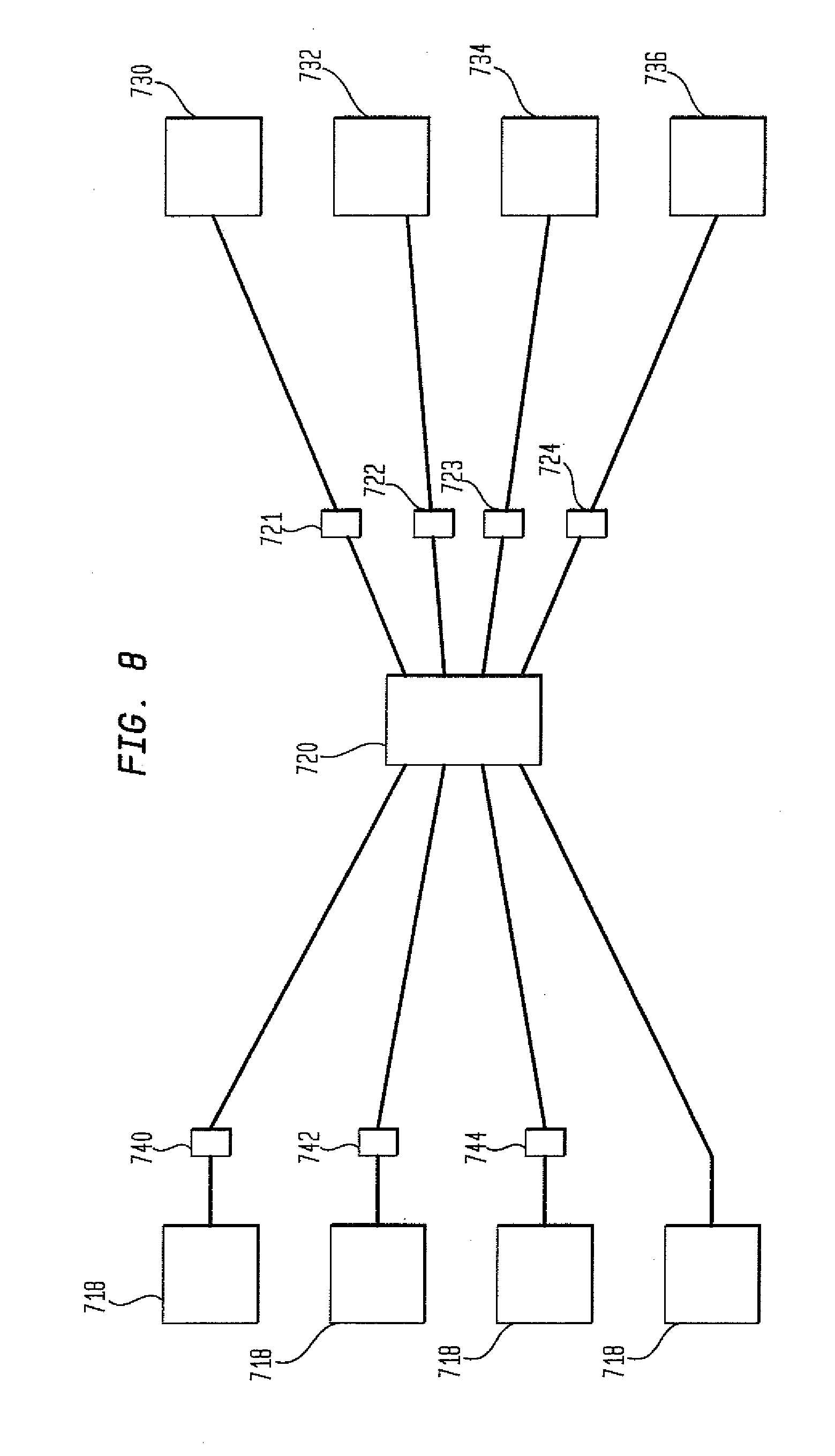
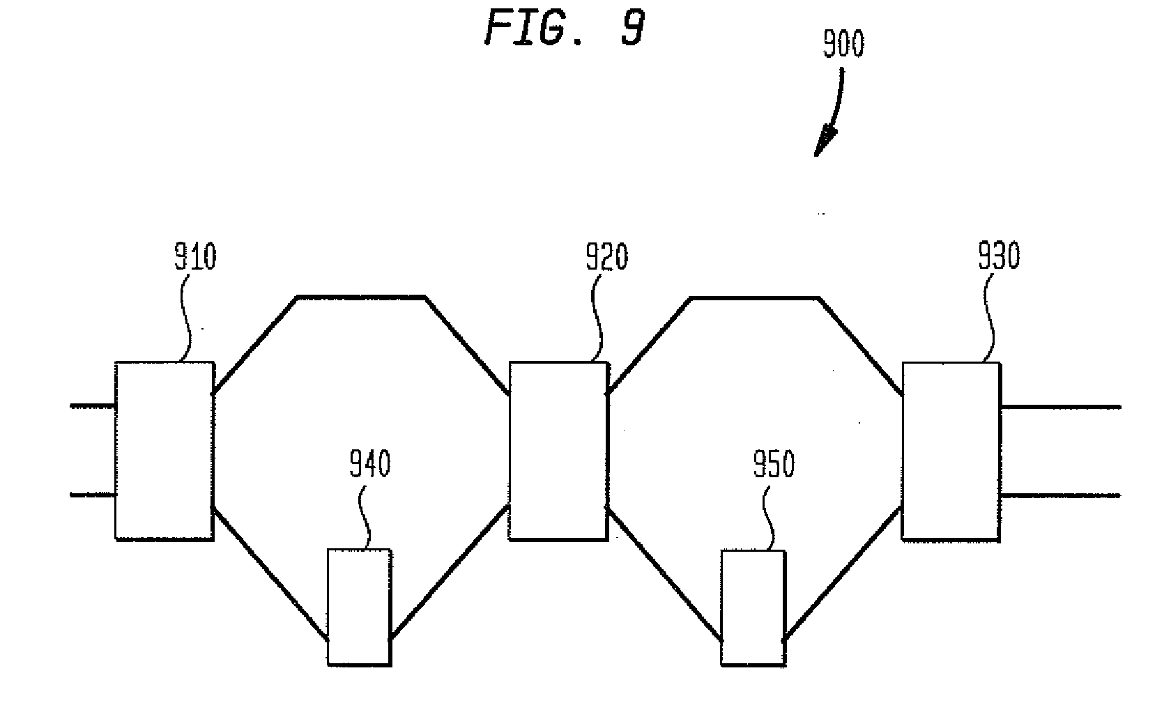
Using the above notation, groups of Hadamard codes can be identified. In general, any combination of Walsh terms can be selected and used as a code group label. The remaining combinations of Walsh terms can then be thought of identifiers for the members of each group. As an example, consider the code group W1, W2, W4, W8, W16. . . WN. Although any number of Walsh terms may be used, in this example, the first two Walsh terms, W1and W2, are chosen as the labels for the code groups. Therefore, there are four different code labels and four different code groups. (W1W2, W1W2, W1W2, W1W2). Thus, all those codes that include both W1and W2terms are in the W1W2group; codes that include W1but not W2terms are in the W1W2group; codes that do not include W1but include W2terms are in the W1W2group; and codes that do not include W1or W2are in the W1W2group. The remaining Walsh terms serve as group member identifiers. That is, these terms differentiate the members of the groups. So, for the example of N=32 and selecting two Walsh terms as the group label, we arrive at a maximum of four groups with up to 8 codes each. The choice of which Walsh terms to use as labels is entirely arbitrary at this point, that is, any pair of Walsh terms would seem to be as good as any other pair as group labels. An optical broadcast-and-select network in accordance with an aspect of the invention is depicted in The encoded signals are sent to a star coupler 720. The star coupler 720 is passive optical coupler having a number of input and output ports. An optical signal introduced into any input port is distributed to all output ports. Because of the nature of the construction of a passive star coupler, the number of ports is usually a power of 2. The outbound legs of the star coupler connect to matching groupings of decoders 730, 732, 734, and 736. Decoder group 730 decodes signals corresponding to the group W1W2. Decoder group 732 decodes signals corresponding to the group W1W2. Decoder group 734 decodes signals corresponding to the group W1W2. Decoder group 736 decodes signals corresponding to the group W1W2. Variable coders 721, 722, 723, and 724 are positioned on the outbound legs of the star coupler. Each variable coder is adjustable to any of the four label states of decoders 730, 732, 734, and 736. Such decoders may be located in a receiving station 180 as shown in Although As was pointed out earlier, in the network configuration in In In As another example, if a signal emanating from element 716, which encodes signals with a W1W2label is transmitted and its desired destination is element 730 which receives signals with a W1W2label, the signal passes through star coupler 720 to variable encoder 721. Variable encoder 721 or 900 sets crossbar switches 910 and 920 so that the signal passes through coders 940 and 950. In accordance with the rules outlined in equations 1 If, however, the desired destination for a signal emanating from element 710 was element 734, which receives signals with the label W1W2, switch 910 would be set so that the signal passes through coder 940 (W1W1=1; thereby removing the label W1) and switch 920 is set so that signal bypasses coder 950. As such, any incoming signal could be relabeled using the rules outlined in equations 1 Although variable coder 900 was described using two coders 940 and 950, any number of coders may be used depending on the label size. For instance if the label size was three, then three coders may be used in coder 900. If the label size was four then four coders may be used in variable coder 900. Alternatively, each coder (940 and 950) may be constructed with multiple codes. For instance coder 940 may include a W1W2coder and coder 950 may include W1W4coder. The combination of such coders may be used to generate Hadamard codes H1, H4, H6, and H7that may be used to label signals. One of the reasons for interest in OCDMA is that it may provide physical-layer obscurity for high-bandwidth signals. Recent analysis of the eavesdropping protection provided by SPE and other types of OCDMA point out that such systems are most vulnerable to eavesdropping when only a single code is present on a link (as would typically be case on the inbound links to a central star coupler). However, one can envision a network scenario consisting of multiple secure islands within which Hadamard coding would be used for signal routing/addressing purposes, but before these signal groups exit the secure islands they would be scrambled by passing through a shared randomly-chosen scrambling stage. Specifically, we must assume that the groups of codes leaving the secure island are always sent simultaneously, as would be the case if large bandwidth signals were being sent on several codes in parallel by inverse multiplexing. We describe a novel optical networking concept enabling the routing of groups of SPE OCDMA Hadamard-coded signals. The foundation of code grouping is the set of functions which form a multiplicative basis underlying the Hadamard codes. In the above description, Walsh codes were used as an example to illustrate the foundation for code grouping although any spanning group of Hadamard codes would also suffice for this purpose. We have described how this code-grouping concept permits groups of SPE Hadamard codes to be passively “labeled” and routed as groups on the basis of those labels. Furthermore, it possible to physically separate the code labeling functions from the assembly of the code group and thereby use identical sets of coders within each group. The ability to deal with groups of codes has important implications for the overall signal obscurity provided by OCDMA. In large measure, OCDMA signal obscurity rests on codes obscuring one another. If several lower-data-rates codes are used to transmit one larger data rate signal (via inverse multiplexing), signal obscurity is enhanced at the physical layer because the group of codes forms a mutually self-obscuring set. Thus, the ability to perform “group routing” is a natural complement to use of inverse multiplexing to form a self-obscuring signal and would be particularly advantageous in these scenarios. Although the invention herein has been described with reference to particular embodiments, it is to be understood that these embodiments are merely illustrative of the principles and applications of the present invention. It is therefore to be understood that numerous modifications may be made to the illustrative embodiments and that other arrangements may be devised without departing from the spirit and scope of the present invention as defined by the appended claims. The invention is directed to code labeling in an optical network. The network includes a transmitting station operable to transmit an optical signal. The network also includes an encoder coupled to the transmitting station operable to label the optical signal composed of a group of codes. A receiving station operable to receive the labeled group of optical codes is also provided. The receiving station is operable to read the optical signal if the label of the received group of codes corresponds to the group of codes assigned to the receiving station. 1. An optical network comprising:
a transmitting station operable to transmit an optical signal having a group of coded optical signals; an encoder coupled to the transmitting station operable to label the optical signal having the group of coded optical signals; and a receiving station operable to receive the labeled optical signal, the receiving station is operable to read the labeled optical signal if the code used to label the group of codes corresponds to the label associated with the receiving station. 2. The optical network according to 3. The optical network according to 4. (canceled) 5. (canceled) 6. (canceled) 7. (canceled) 8. (canceled)STATEMENT REGARDING FEDERALLY SPONSORED RESEARCH
FIELD OF THE INVENTION
BACKGROUND OF THE INVENTION
SUMMARY OF THE INVENTION
BRIEF DESCRIPTION OF THE DRAWINGS
DETAILED DESCRIPTION OF THE INVENTION
H1= W0 H2= W1 H3= W2 H4= W2*W1 H5= W4 H6= W4*W1 H7= W4*W2 H8= W4*W2*W1 H9= W8 H10= W8*W1 H11= W8*W2 H12= W8*W2*W1 H13= W8*W4 H14= W8*W4*W1 H15= W8*W4*W2 H16= W8*W4*W2*W1
where the underlined Walsh terms are understood to be absent from the product and element-by-element product of the Walsh terms is implicit as is the “all 1's” code (W0or H1) which is implicitly included in the above expression. In general, the set of N Hadamard codes are represented in terms of the presence or absence of the log2(N) different Walsh terms. From this viewpoint, the XOR operations take the form of adding or dropping terms in the overall product according to simple rules for the addition or deletion of a Walsh term such as:
WaWa=WaWa=1 (1a)
WaWa=WaWa=Wa (1b)