REFRIGERANT DISTRIBUTION UNIT FOR AIR CONDITIONER
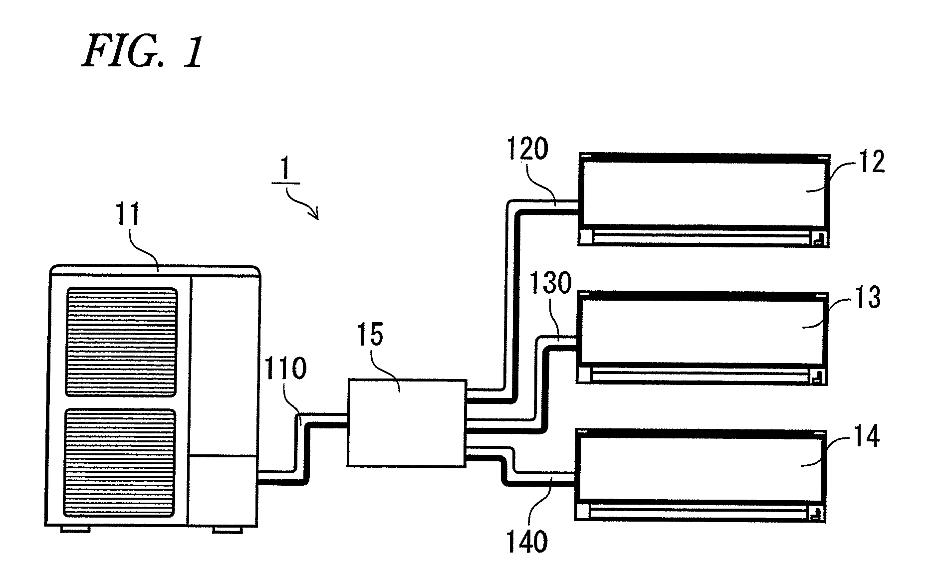
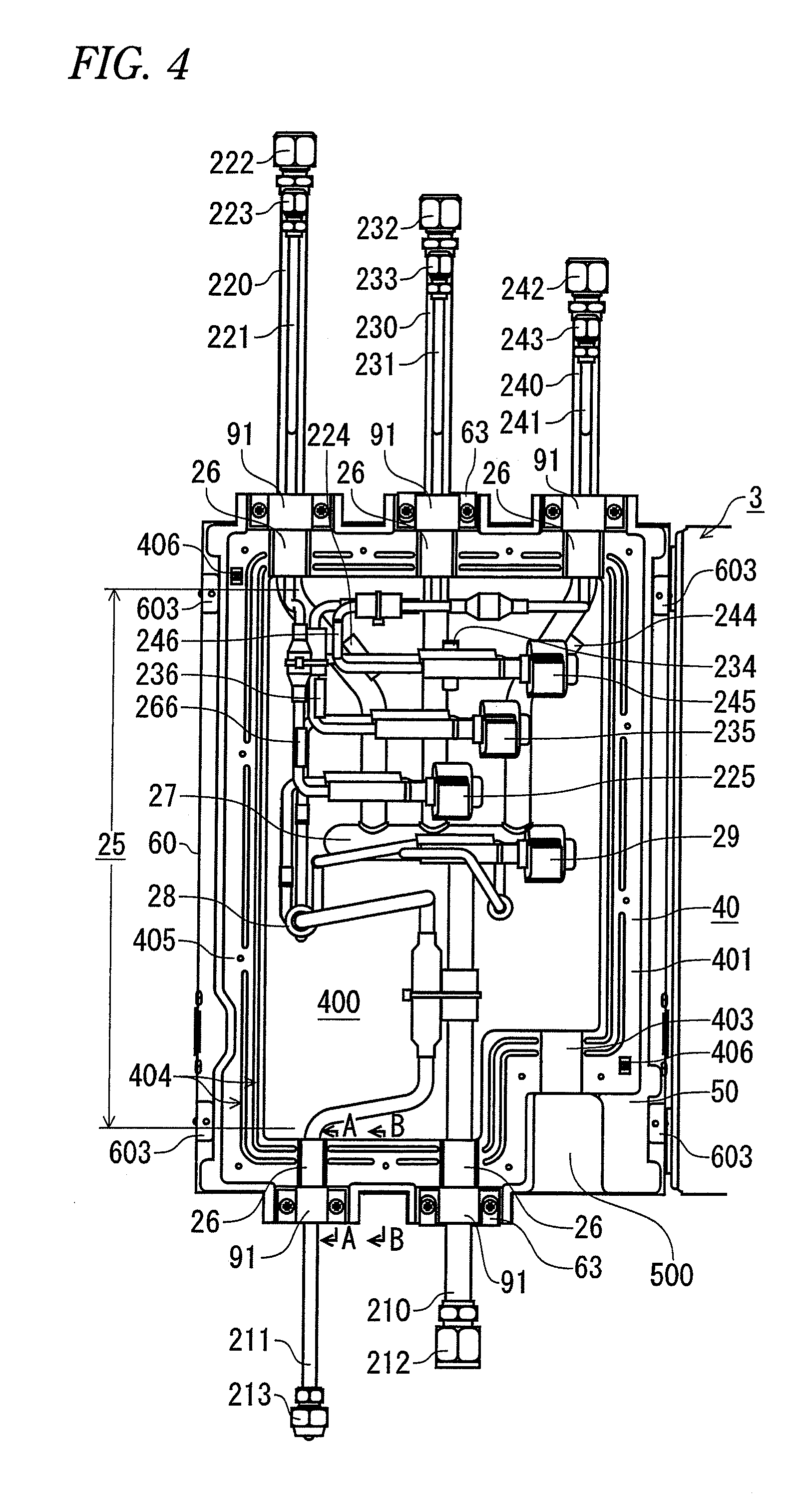
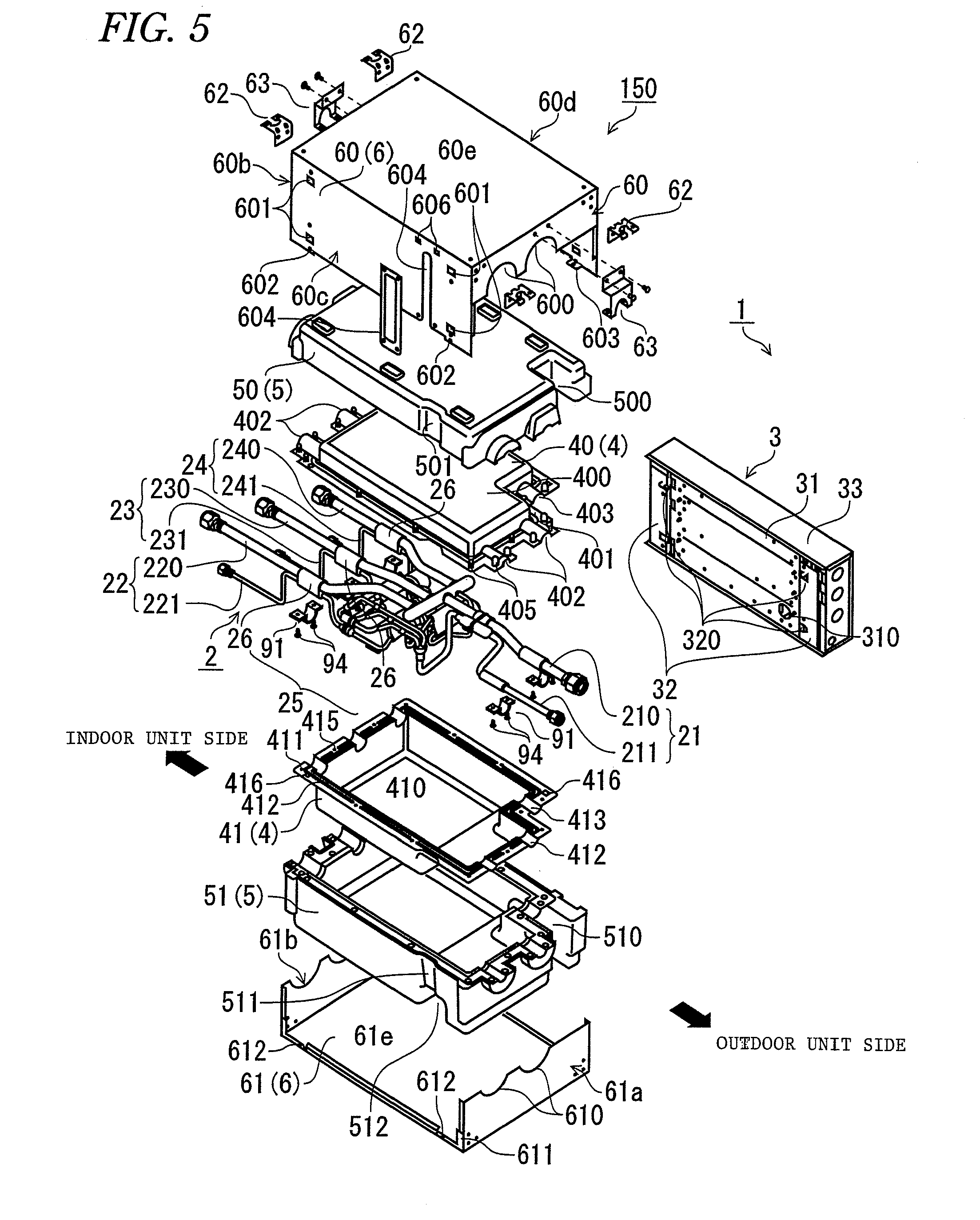
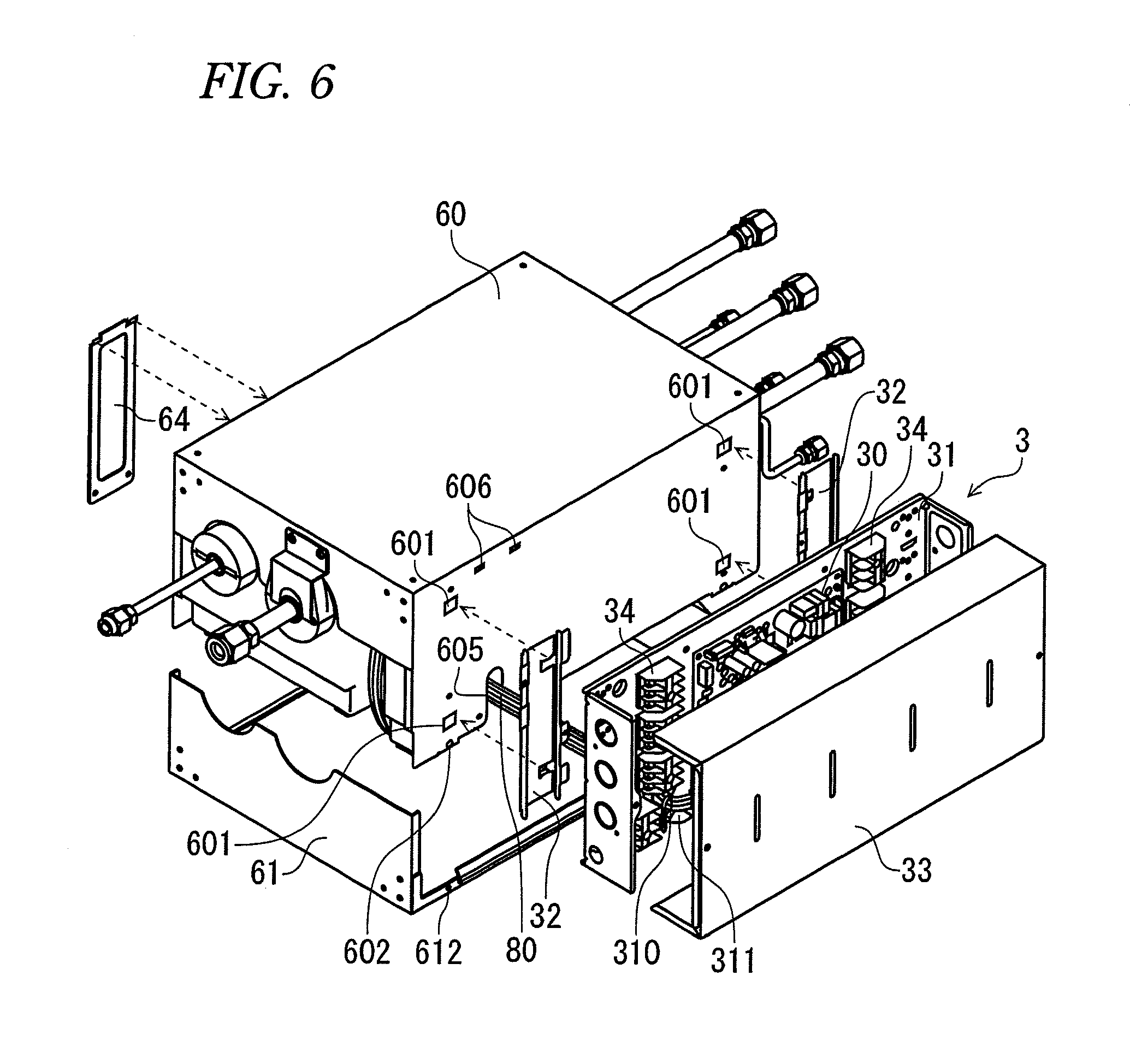
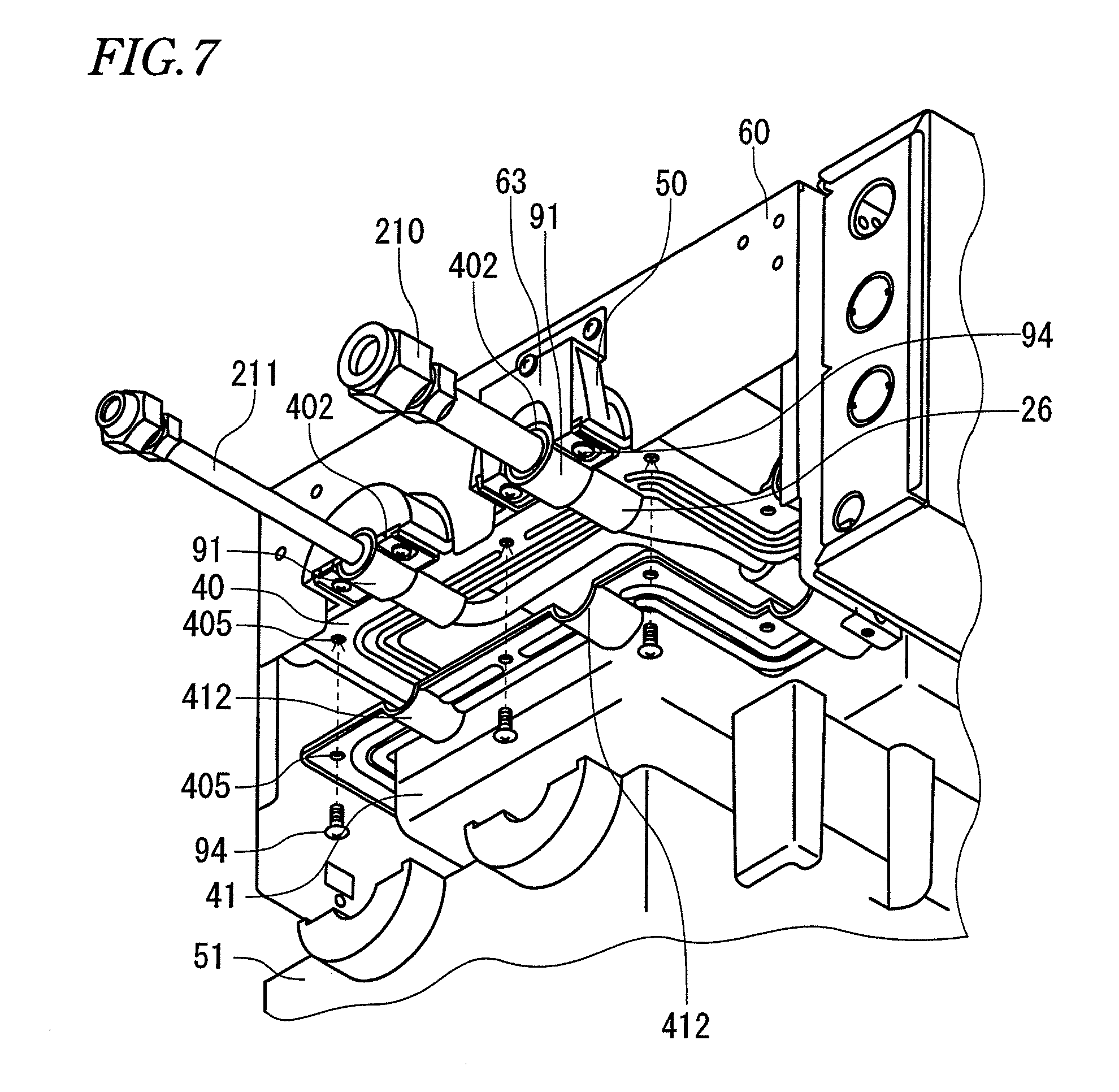
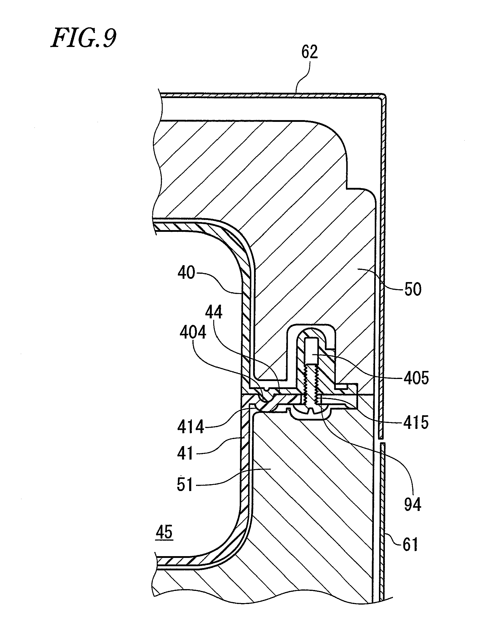
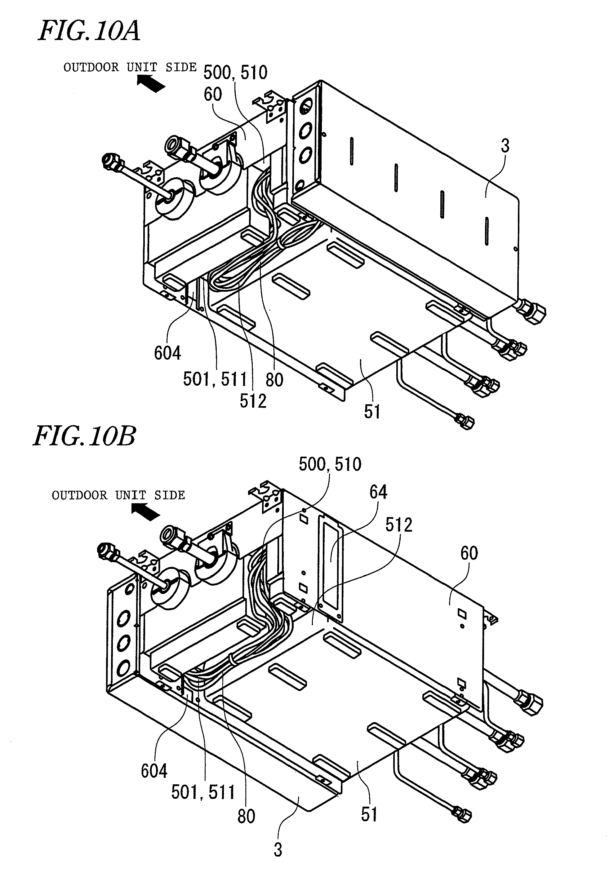
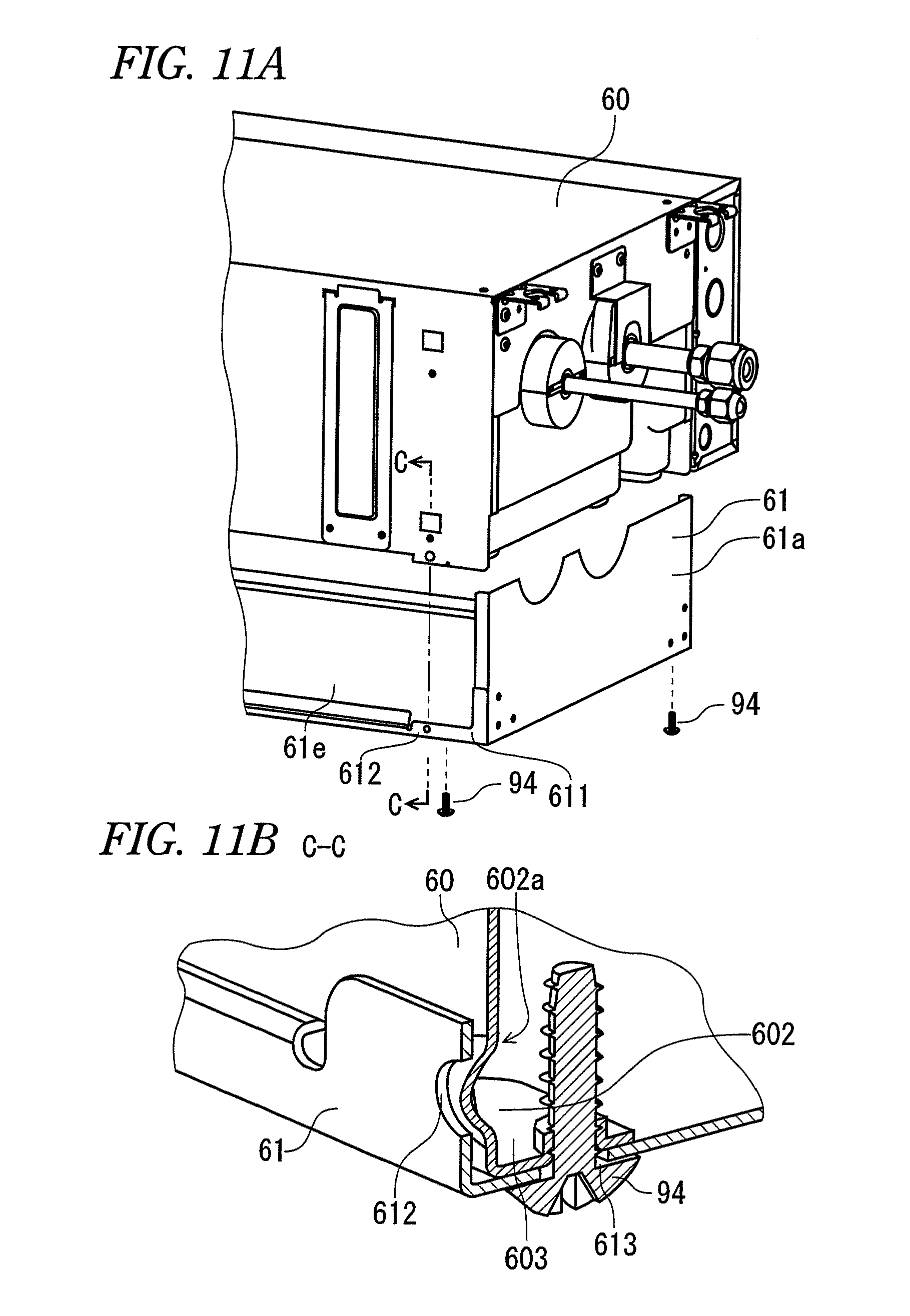
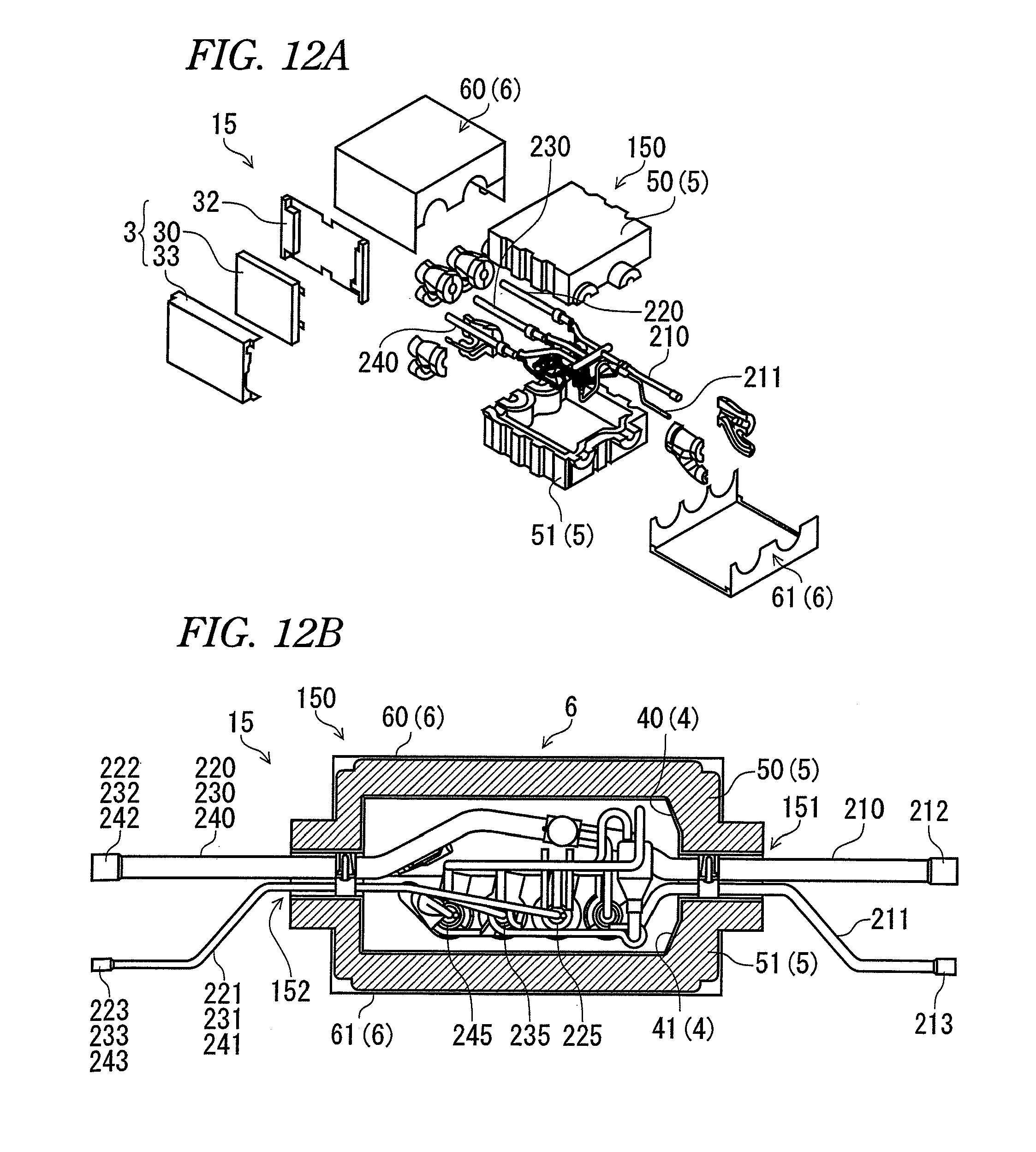
This application claims priority from Japanese Patent Application No. 2010-148520, filed on Jun. 30, 2010, the entire contents of which are hereby incorporated by reference. The present disclosure relates to a refrigerant distribution unit for an air conditioner, which incorporates therein a pipe unit for distributing a refrigerant from an outdoor unit of the air conditioner to multiple indoor units thereof and, more specifically, the invention relates to enhancement in the efficiency of maintenance on such refrigerant distribution unit. The main body 150 includes: a case 6 which is made of a metal plate and includes an upper case 60 and a lower case 61 respectively defining the outer shell portion of the main body 150; an insulator case 5 including an upper insulator case 50 provided within the upper case 60 and a lower insulator case 51 proved within the lower case 61; and, a seal case 4 including an upper seal case 40 provided within the upper insulator case 50 and a lower seal case 41 provided within the lower insulator case 51. The upper case 60, upper insulator case 50 and upper seal case 40 are respectively divided vertically by a refrigerant pipe receiving portion 151 and a branch refrigerant pipe receiving portion 152. Here, the refrigerant pipe receiving portion 151 is a portion through which the refrigerant pipes, that is, the gas pipe 210 and liquid pipe 211 can be inserted, while the branch refrigerant pipe receiving portion 152 is a portion through which the multiple branch refrigerant pipes, that is, the branch gas pipes 220, 230 and 240 and branch liquid pipes 221, 231 and 241 can be inserted. The refrigerant pipes are connected by a gas pipe joint 212 and a liquid pipe joint 213 to refrigerant pipes which are connected to the outdoor unit of the air conditioner. The multiple branch refrigerant pipes are connected by branch gas pipe joints 222, 232 and 242 and branch liquid pipe joints 223, 233 and 243 to refrigerant pipes which are connected to the multiple indoor units of the air conditioner. In the case of the refrigerant pipes, the gas pipe 210 and liquid pipe 211 are bundled together by the refrigerant pipe receiving portion 151, and are held horizontally by the vertically divided upper seal case 40 and lower seal case 41 and by the vertically divided upper insulator case 50 and lower insulator case 51. In the case of the branch refrigerant pipes, the branch liquid pipe 221 and branch gas pipe 220 are bundled together, the branch liquid pipe 231 and branch gas pipe 230 are bundled together, the branch liquid pipe 241 and branch gas pipe 240 are bundled together. The vertically divided multiple branch refrigerant pipe receiving portions 152 are closely contacted with each other, whereby the branch refrigerant pipes can be held horizontally. The refrigerant distribution unit 15, in most cases, is installed (hanged) horizontally on a back face of an indoor ceiling. However, when the lower case 61, lower insulator case 51 and lower seal case 41 are removed in maintenance on the unit 15, since the pipe unit is not fixed to the main body 150, the pipe unit is flexed downward due to its own weight. Due to this, in a state where the refrigerant distribution unit 15 remains hanging on the back face of the ceiling, maintenance on the peripheral parts of the pipe unit is impossible. Therefore, according to the related art, it is necessary to remove the refrigerant distribution unit 15 from the ceiling and take the refrigerant distribution unit 15 to pieces, which results in the poor efficiency of the maintenance. Illustrative aspects of the present invention provide a refrigerant distribution unit for an air conditioner which, in a state where its main body is hanged, allows maintenance on the peripheral parts of its pipe unit without taking the refrigerant distribution unit to pieces. According to a first aspect of the invention, a refrigerant distribution unit for an air conditioner, is provided with: a pipe unit for distributing a refrigerant from a refrigerant pipe provided on an outdoor unit to a plurality of branch refrigerant pipes respectively provided on a plurality of indoor units; and a main body including: an upper seal case and a lower seal case which include first edge portions in a periphery of the upper seal case and second edge portions in a periphery of the lower seal case, and engage the second edge portions with the first edge portions for sealing an inside of the first and second seal cases to store the pipe unit; an upper insulator case and a lower insulator case for covering the upper seal case and the lower seal case respectively; and an upper case and a lower case respectively constituting a contour of the refrigerant distribution unit, wherein the upper seal case includes a pipe mounting portion in which a contact face with the pipe unit is extended from the first edge portions, wherein the pipe unit is fixed to the pipe mounting portion using a pipe holder and a pipe hanging bracket, and wherein an upper portion of the pipe hanging bracket is fixed to the upper case, and a lower portion of the pipe hanging bracket is extended to a lower end of the pipe holder. Other aspects and advantages of the invention will be apparent from the following description, the drawings and the claims. Now, description will be given below specifically of the best mode for carrying out the invention, using an exemplary embodiment thereof with reference to <Air Conditioner> An air conditioner 1 shown in The outdoor unit 11 includes the following composing parts (none of which are shown): that is, an outdoor heat exchanger; a portion of a refrigerant circuit for a compressor, a four way valve and the like; a fan for blasting air in order to exchange heat between a refrigerant within the outdoor heat exchanger and the open air; a fan motor for driving the fan; and a control circuit for controlling the above composing parts. The indoor units 12, 13 and 14 respectively include the following composing parts (none of which are shown): that is, a portion of a refrigerant circuit for an indoor heat exchanger and the like; a fan for blasting air in order to exchange heat between a refrigerant within the indoor heat exchanger and the open air; a fan motor for driving the fan; and a control circuit for controlling the above composing parts. The refrigerant circuit of the outdoor unit 11 is connected to the refrigerant circuits of the indoor units 12, 13 and 14 through an outdoor unit side pipe 110 and indoor unit side pipes 120, 130 and 140 respectively. Between the outdoor unit 11 and the multiple indoor units 12, 13 and 14, there is interposed a refrigerant distribution unit 15 which is used to distribute refrigerants uniformly refrigerant from the outdoor unit side pipe 110 to the indoor unit side pipes 120, 130 and 140. <Refrigerant Distribution Unit> The refrigerant distribution unit 15 shown in The refrigerant distribution unit 15 is horizontally hanged from and fixed to an indoor ceiling or the like by multiple pieces of ceiling-mounting brackets 62. And, in order to adjust to the environment of the ceiling which is liable to be hot and humid, especially, the inside of the main body 150 is structured such that it has an insulating property which can prevent it against the influence of temperature variations and also that it is sealed in order to prevent it against the influence of humidity. The pipe unit 2, as shown in The refrigerant pipe 21 includes a gas pipe 210 and a liquid pipe 211. The gas pipe 210 includes a gas pipe joint 212 in the vicinity of the refrigerant distribution unit 15, while the liquid pipe 211 includes a liquid pipe joint 213 in the vicinity of the refrigerant distribution unit 15. Due to the gas pipe joint 212 and liquid pipe joint 213, the gas pipe 210 and liquid pipe 211 can be connected to and removed from the outdoor unit side pipe 110. The gas pipe 210 and liquid pipe 211 are arranged horizontally and are spaced 40 mm or more from each other, while they can be stored into the main body 150 from a refrigerant pipe receiving portion 151. The branch refrigerant pipes 22, 23 and 24 include branch gas pipes 220, 230 and 240 and branch liquid pipes 221, 231 and 241, respectively. The branch gas pipes 220, 230 and 240 include branch gas pipe joints 222, 232 and 242 in the vicinity of the refrigerant distribution unit 15, respectively; and the branch liquid pipes 221, 231 and 241 include branch liquid pipe joints 223, 233 and 243 on a side of the refrigerant distribution unit 15, respectively. Due to the branch gas pipe joints 222, 232 and 242 and branch liquid pipe joints 223, 233 and 243, the branch refrigerant pipes 22, 23 and 24 can be connected to and removed from the indoor unit side pipes 120, 130 and 140, respectively. The branch gas pipes 220, 230 and 240 are respectively formed to have a linear shape. The branch liquid pipes 221, 231 and 241 are respectively disposed downwardly of and spaced a given distance from the branch gas pipes 220, 230 and 240, and are bent upwardly on the side of the main body 150; after then, they are respectively bundled together by their associated rubber bushes 26 such that the branch gas pipe 220 and branch liquid pipe 221 are formed into a unified body, the branch gas pipe 230 and branch liquid pipe 231 are formed into a unified body, and the branch gas pipe 240 and branch liquid pipe 241 are formed into a unified body. Also, the branch refrigerant pipes 22, 23 and 24 are arranged horizontally and are spaced 40 mm or more from each other, while the branch refrigerant pipes 22, 23 and 24 can be stored into the main body 150 from a branch refrigerant pipe receiving portion 152. <Branch Portion> The branch portion 25 of the pipe unit 2 shown in <Cable> To the branch gas pipe temperature sensors 224, 234 and 244 and branch liquid pipe temperature sensors 226, 236 and 246, there are connected signal lines for transmitting the detected results of the sensors 224, 234, 244, 226, 236 and 246 to the control substrate 30 of the electric component box 3. To the electronic expansion valves 225, 235 and 245 as well as to the on/off valve 29, there are connected wires which are used to drive the valves 225, 235, 245 and 29 respectively. The signal lines and wires are bundled together to provide a cable 80, while the cable 80 is connected to the control substrate 30 of the electric component box 3. <Main Body> The main body 150 shown in <Seal Case> The seal case 4 is formed of synthetic resin and includes an upper seal case 40 and a lower seal case 41 which are divided vertically along centers of pipe diameters of the horizontally extending refrigerant pipe 21 and branch refrigerant pipes 22, 23 and 24. The upper seal case 40 shown in In the edge portion 401, specifically, on the refrigerant pipe receiving portion 151 for receiving the refrigerant pipe 21 and also on the branch refrigerant pipe receiving portion 152 for receiving the branch refrigerant pipes 22, 23, 24, there are provided (there are extended continuously therefrom) pipe mounting portions 402 which respectively draw a semi-circular shape along the pipes. On the semi-circular right and left end portions of the pipe mounting portion 402, there are erected anchors 405 which are respectively used to receive screws (which will be discussed later). Also, there is also formed a cable draw-out portion 403 which has a semi-circular shape and is used to draw out the cable 80. Further, in the edge portion 401, there are provided projecting ribs 404 which extend in two lines in such a manner as to surround the storage portion 400. On the projecting ribs 404, there are bonded insulating seals 44 (see Of the two-lined projecting ribs 404, the projecting rib 404 disposed outside includes the anchors 405 which are respectively erected and are spaced from each other for receiving screws (which will be discussed later). The anchors 405 are further erected on the four corners of the edge portion 401 as well. The lower seal case 41 includes a storage portion 410 for storing the branch portion 25 of the pipe unit 2, and an edge portion 411 which is formed on the periphery of the storage portion 410 and is used to keep the sealing property of the storage portion 410. In the edge portion 411, specifically, in such portions of the edge portion 411 as are to be contacted with the refrigerant pipe 21 and branch refrigerant pipes 22, 23 and 24, there are continuously formed pipe mounting portions 412 which respectively have a semi-circular shape; and also, there are continuously formed cable draw-out portions 413 which respectively have a semi-circular shape. Also, in the edge portion 411, there are formed recessed ribs 412 which are used to receive the projecting ribs 404 respectively. Further, there are formed screw holes 415 which can be engaged with their associated anchors 405. <Insulator Case> The insulator case 5 is formed of highly heat-resisting styrene foam and has a constant thickness over the entire area thereof in order to enhance its heat-resisting property. Such portions of the insulator case 5 as correspond to the refrigerant pipe receiving portion 151 and branch refrigerant pipe receiving portion 152 are respectively projected out in a cylindrical manner; and the insulator case 5 is divided into an upper insulator case 50 and a lower insulator case 51 along the centers of the pipe diameters of the refrigerant pipe 21 and branch refrigerant pipes 22, 23 and 24. A shape of the inside of the upper insulator case 50 is formed to fit the outer shape of the upper seal case 40. Also, the upper insulator case 50 includes a cable draw-out recessed portion 500 which is formed to fit the cable draw-out portion 403 of the upper seal case 40. And, in the left side face of the upper insulator case 50 when viewed from the outdoor unit side, there is formed a cable side face recessed portion 501 which is used to introduce the cable 80 which has been drawn out, into the electric component box 3. A shape of the inside the lower insulator case 51 is formed to fit the outer shape of the lower seal case 41. Also, the lower insulator case 51 includes a cable draw-out recessed portion 510 which is formed to fit the cable draw-out portion 413 of the lower seal case 41. And, in the left side face of the lower insulator case 51 when viewed from the outdoor unit side, there is formed a cable side face recessed portion 511 which is used to introduce the cable 80 which has been drawn out, into the electric component box 3. Further, in the bottom face of the lower insulator case 51, there is formed a bottom face recessed portion 512 for the cable. <Case> The case 6, which constitutes the contour of the main body 150, can be formed by bending a metal sheet. And, the case 6 includes an upper case 60 and a lower case 61. The upper case 60 has a box-like shape. Specifically, the upper case 60 includes an outdoor unit side lateral portion 60 The outdoor unit side lateral portion 60 The first lateral portion 60 In the first lateral portion 60 The lower case 61 has a U-like shape and includes an outdoor unit side lateral portion 61 The outdoor unit side lateral portion 61 A metal plate, which is used to form the lower case 61, includes flange portions 611 which are formed by extending two end portions of the bottom face portion 61 The flange portions 611 respectively include dowel holes 612 to which, when the lower case 61 is assembled, there can be removably secured the dowels 602. In such portions of the bottom face portion 61 <Electric Component Box> The electric component box 3 shown in The electric component box main body 31 is constituted of a metal plate having a U-like shape; and, within the U-like shape, there are disposed the control plate 30 and multiple terminal bases 34. In a portion of the electric component box main body 31, there is formed a cable guide hole 310 which is used to guide the cables 80; and, in such inside portion of the electric component box main body 31 as exists near to the cable guide hole 310, there is provided a cable guide 311 which is used to bundle together the cables 80 and guide them to the control substrate 30. The mounting plates 32 respectively have a rectangular shape, include securing pawls 320 so formed in the two upper and lower portions thereof as to be bent inwardly symmetrically, and are welded to the right and left portions of the outside of the electric component box main body 31. <Assembling Method> The refrigerant branch unit 15 may be assembled in such a manner that, when compared with its installing state where it is hanged down from the ceiling, it is turned upside down. First, the upper case 60 is placed with its ceiling face portion 60 Next, as shown in Next, as shown in The cables 80 are bundled together by a binding tool 82 and are drawn out to the outside from the cable receiving portion 403 of the upper seal case 40. According to the above-mentioned configuration, the pipe unit 2 is fixed to the pipe mounting portion 402 of the upper seal case 40 by the pipe holder 91 and pipe hanging bracket 63. The upper portion of the pipe hanging bracket 63 is fixed to the upper case 60 and the lower portion of the pipe hanging bracket 63 extends down to the lower end of the pipe holder 91. Thus, the branch portion 25, electronic expansion valves 225, 235 and 245, etc. respectively constituting the pipe unit 2 are exposed to the outside by removing the lower case 60, lower insulator case 51 and lower seal case 41. Therefore, it is possible to carry out maintenance on the pipe unit 2 without taking the main body 150 to pieces. Next, the seal case securing hole 410 of the lower seal case 41 is inserted in such a manner that the seal case securing hole 410 can be engaged with the seal case securing pawl 406 projected from the upper seal case 40. In the case that the upper seal case 40 and lower seal case 41 are engaged with each other, the recessed rib 414 of the lower seal case 41 is closely contacted with the projecting rib 404 of the upper seal case 40 through the insulating seal 44 with no gap between the projecting rib 404 and the recessed rib 414. Next, screws 94 are engaged through screw holes 415 with the anchors 405 which are respectively provided in the multiple portions of the edge portion 401. As shown in Next, the lower insulator case 51 is placed on top of the lower seal case 41. In this case, besides the lower insulator case 51, the screws 94, which have been engaged with the pipe holder 91 and pipe hanging bracket 63, are also covered with the lower insulator case 51. This can also prevent water or like from touching the screws 94. The electric component box 3 may be mounted onto any one of the first and second lateral portions 60 The thus drawn-out cables 80, as shown in The electric component box main body 31, which has been connected to the cables 80, inserts the securing pawl 320 of the mounting plate 32 welded to the electric component box main body 31 into the securing hole 601 of the upper case 60. In this case, the securing pawl 320, specifically, the upper pawl thereof is held in a state where the upper pawl is hanging down, whereby the electric component box 3 is provisionally fixed by the securing pawl 320. Next, the electric component box 3 is engaged from inside of the electric component box main body 31 with the upper case 60 using screws. As a result, the electric component box 3, which is provisionally fixed by the securing pawl 320, is fixed. Then, the electric component box cover 33 is placed on top of the electric component box 3. Also, as shown in The cables 80, which have been guided to the cable bottom face recessed portion 512, are moved over the cable bottom face recessed portion 512, are moved through the cable side face recessed portions 501 and 511, are drawn out from above the first cable draw-out slot 604 to the outside of the main body 150, and are guided from the cable guide hole 310 of the electric component box main body 31 into the electric component box 3. According to the mounting method, for example, even when moving the electric component box 3 from one place to the other place according to the site where the is electric component box 3 mounted in the air conditioner is installed, the electric component box 3 can be moved simply with the cables 80 remaining connected. Next, a cable draw-out slot cover 64 is mounted onto any one of the first cable draw-out slot 604 and second cable draw-out slot 605 which are formed in the portion of the upper case 60 where the electric component box 3 is not installed. Since the cable draw-out slot cover 64 is formed longer than the cable draw-out slot 604, and also since cable draw-out cover holes 606 are formed at the symmetric positions of the first and second lateral portions 60 Next, the lower case 61 is assembled to the upper case 60 in such a manner as shown in When carrying out maintenance on the pipe unit 2, the screws 94 engaged with the screw mounting portion 603 are removed. In this case, even when the screws 94 are removed, the lower case 61 is fixed provisionally because of engagement of the dowel 602 into the dowel hole 612. Therefore, there is no fear that the lower case 61 can fall down unexpectedly. Also, the base portion 602 As described above, the structure capable of provisionally fixing the lower case 61 to the upper case 60 in a removable manner is a structure which includes the dowel 602 provided on the upper case 60 and the dowel hole 612 formed in the lower case 61. That is, the present structure is characterized in that it is possible to fix the lower case 61 provisionally without using any new parts. Here, the dowel 602 and dowel hole 612 are not limited to the above-mentioned structures. And, there may also be employed a structure in which the dowel hole 612 is formed in the upper case 60 and the dowel 602 is provided on the lower case 61. As has been described heretofore, according to the exemplary embodiment, since the pipe unit 2 is fixed to the upper case 60 by the pipe hanging metal fittings 63, it is possible to provide a refrigerant branch unit for use in an air conditioner, in which, when carrying out maintenance on the branch portion 25, electronic expansion valve 225, 235, 245 and the like which constitute the pipe unit 2, by removing the lower case 61, lower insulator case 51 and lower seal case 41 with the main body 150 remaining mounted, the above-mentioned parts of the pipe unit 2 can be maintained without taking the main body 150 to pieces. While the present inventive concept has been shown and described with reference to certain exemplary embodiments thereof, it will be understood by those skilled in the art that various changes in form and details may be made therein without departing from the spirit and scope of the invention as defined by the appended claims. A refrigerant distribution unit for an air conditioner, includes: a pipe unit for distributing a refrigerant from a refrigerant pipe on an outdoor unit to branch refrigerant pipes on indoor units; and a main body including: upper and lower seal case which include first edge portions around the upper seal case and second edge portions around the lower seal case, and engage the second edge portions with the first edge portions for sealing an inside of the first and second seal cases to store the pipe unit; upper and lower insulator cases for covering the upper and lower seal cases; and upper and lower case constituting a contour of the refrigerant distribution unit. The pipe unit is fixed to a pipe mounting portion of the upper seal case using a pipe holder and a pipe hanging bracket. 1. A refrigerant distribution unit for an air conditioner, comprising:
a pipe unit for distributing a refrigerant from a refrigerant pipe provided on an outdoor unit to a plurality of branch refrigerant pipes respectively provided on a plurality of indoor units; and a main body including:
an upper seal case and a lower seal case which include first edge portions in a periphery of the upper seal case and second edge portions in a periphery of the lower seal case, and engage the second edge portions with the first edge portions for sealing an inside of the first and second seal cases to store the pipe unit; an upper insulator case and a lower insulator case for covering the upper seal case and the lower seal case respectively; and an upper case and a lower case respectively constituting a contour of the refrigerant distribution unit, wherein the upper seal case includes a pipe mounting portion in which a contact face with the pipe unit is extended from the first edge portions, wherein the pipe unit is fixed to the pipe mounting portion using a pipe holder and a pipe hanging bracket, and wherein an upper portion of the pipe hanging bracket is fixed to the upper case, and a lower portion of the pipe hanging bracket is extended to a lower end of the pipe holder. 2. The refrigerant distribution unit according to wherein the pipe hanging bracket and the pipe holder are fastened to the pipe mounting portion.FIELD OF THE INVENTION
DESCRIPTION OF RELATED ART
SUMMARY OF INVENTION
BRIEF DESCRIPTION OF THE DRAWINGS
DETAILED DESCRIPTION OF EXEMPLARY EMBODIMENTS