Bipolar Connector System
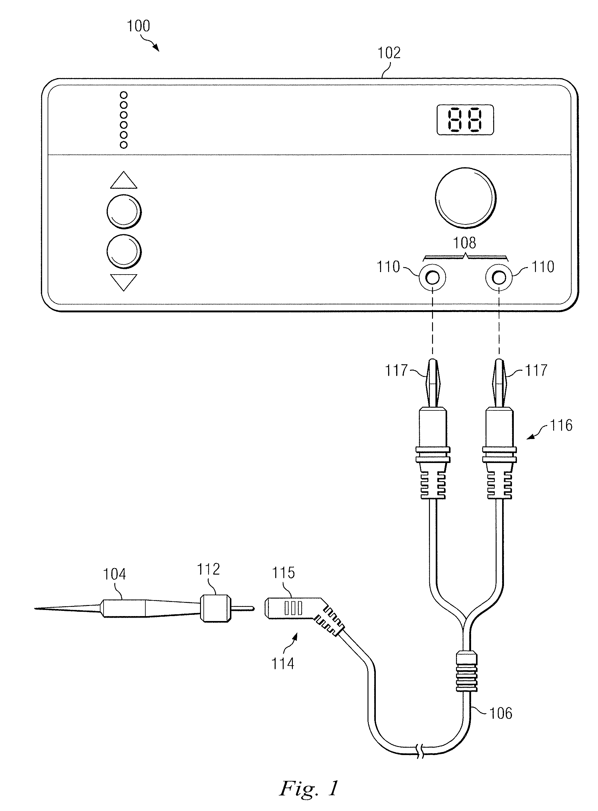
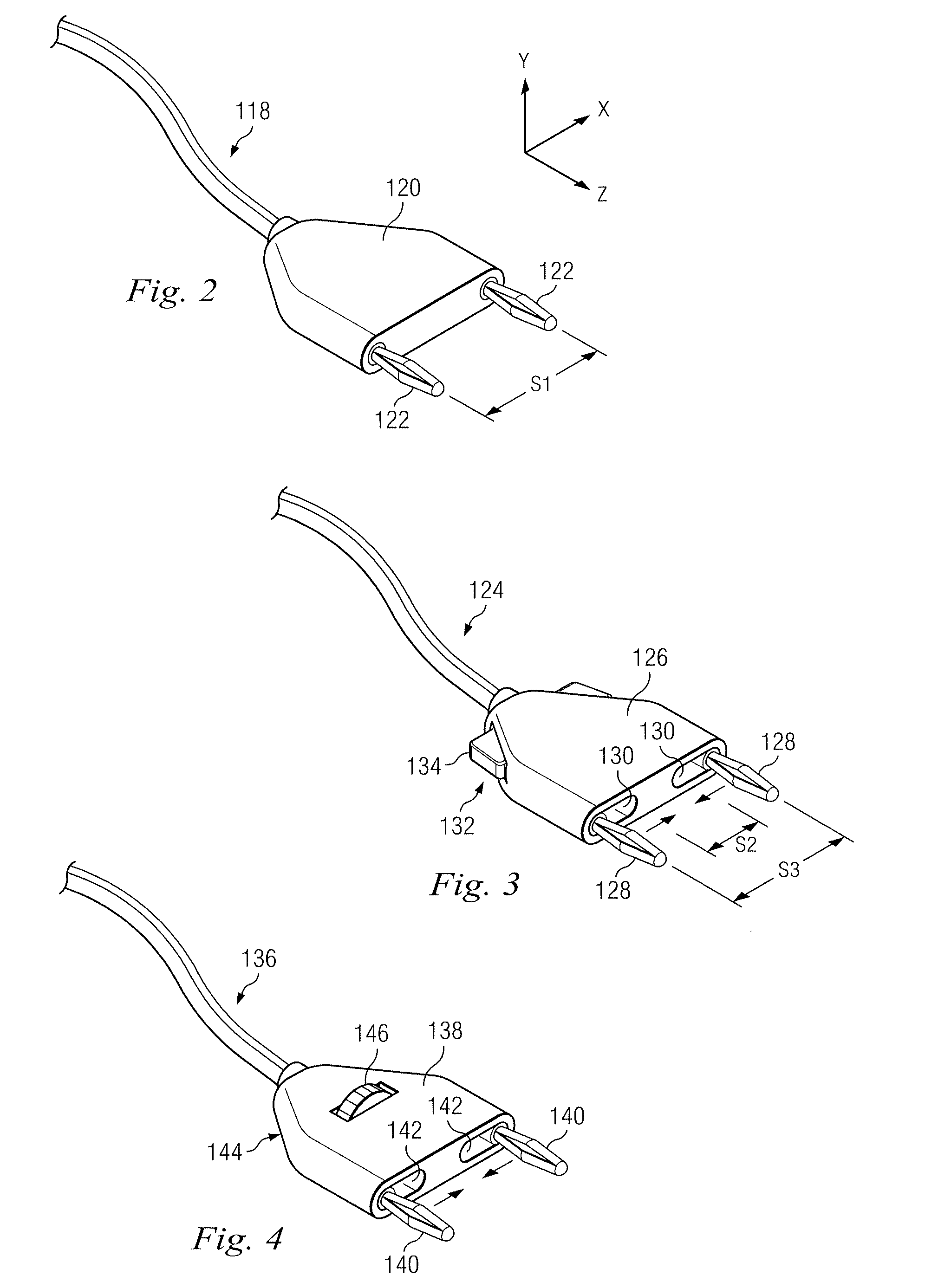
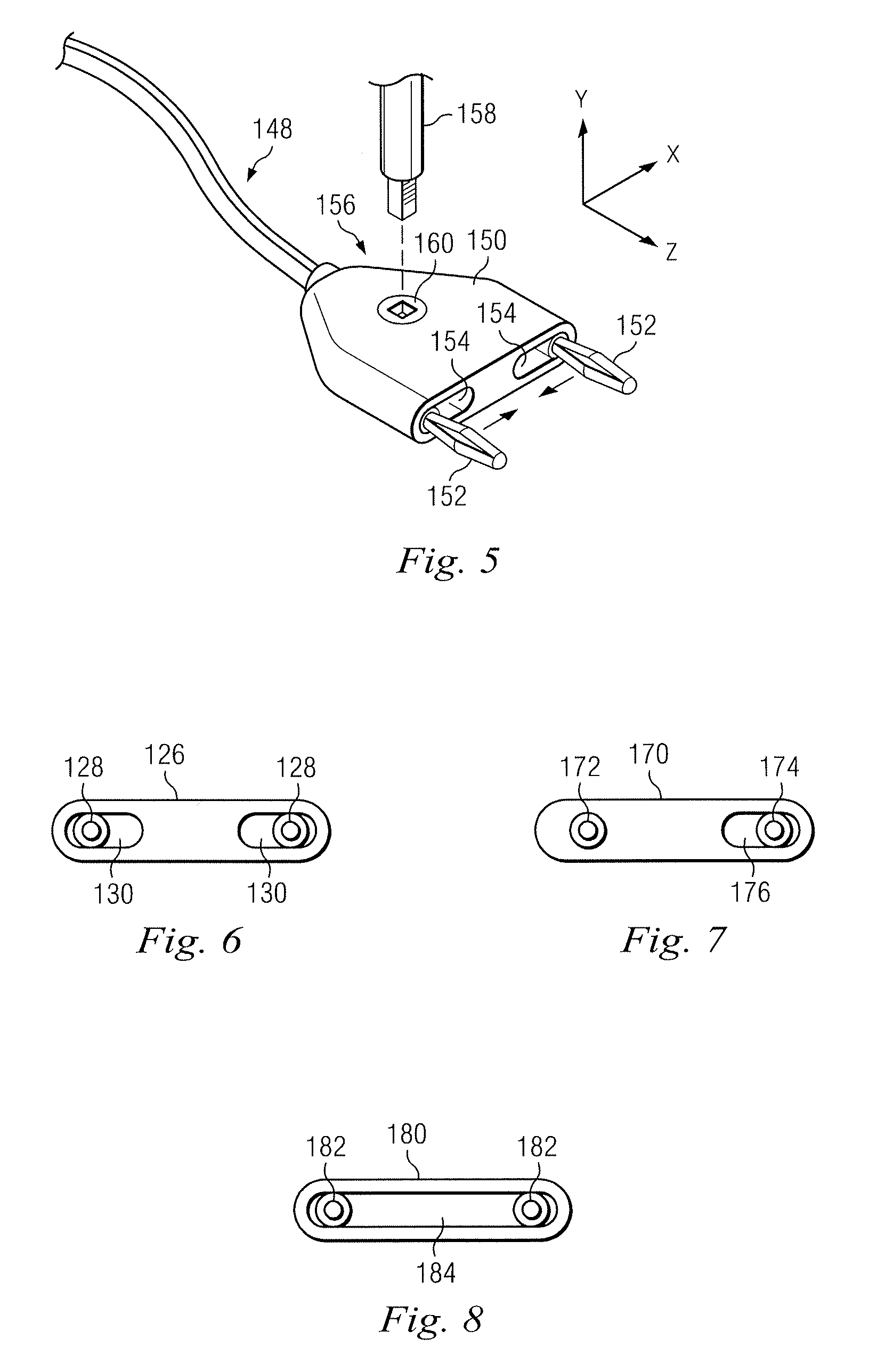
This disclosure relates in general to a system for connecting instruments to a console and more particularly to a system for connecting bipolar medical instruments to a console. Electrosurgical instruments use high frequency electrical energy to cut, coagulate, cauterize, or otherwise treat biological tissue. The instruments, when in contact with tissue, allow for the passage of a high frequency current along a pathway from an active electrode, through tissue, and then to a ground or return electrode. The current flow allows the surgeon to cut or coagulate tissue by varying parameters such as power, contact time, wave form, frequency, etc. Electrosurgical instruments may have various configurations including probes, scissors, and forceps. There are two common types of electrode configurations used in electrosurgical systems: monopolar and bipolar configurations. In monopolar electrosurgery, current flows from a generator to a single active electrode, such as a lancet or scalpel held by a surgeon. The current passes through the patient's body to a dispersive pad, which is the ground electrode, and back to the generator. The dispersive pad covers a large portion of the patient's body relative to the size of the active electrode, thus preventing tissue damage or significant heat buildup by allowing the current to spread over a larger area. In bipolar electrosurgery, current flows from the generator to a surgical instrument, such as forceps. One tine of the forceps acts as the active electrode and directs the current through the patient tissue to the other tine, which acts as the return electrode and enables the flow to return to the generator to complete the circuit. A dispersive pad is not required for bipolar surgery. Typically, electrosurgical instruments are connected to a generator housed in a console using a connecting device such as a connector cable. Cables to connect bipolar instruments to the console typically have two electrical connectors while monopolar instruments only require one connector. The bipolar electrical connectors may be configured as separated “flying leads,” but this configuration may pose a safety concern. For example, one of the connectors may be inserted into the console while the other remains unconnected or the other lead may be inadvertently inserted into the wrong receptacle on the console. Accordingly, there is a need for improved connector cables, particularly for bipolar cables that can minimize the risk of improperly connecting the cable to the electric generator console. There is also a need for connector cables that may comply with increased safety and utility standards such as those promulgated by the International Electrotechnical Commission (IEC) under the guidelines of IEC 60601-2-2. In one exemplary aspect, an electrical connector assembly comprises a first elongated connector in parallel alignment with a second elongated connector and an adjustment mechanism operable to control movement of the first elongated connector relative to the second elongated connector while maintaining parallel alignment between the elongated connectors. In another exemplary aspect, an electrosurgical system comprises a bipolar surgical instrument and an electrical connector assembly to connect the bipolar surgical instrument to one or more surgical consoles. The electrical connector assembly includes a first elongated connector in parallel alignment with a second elongated connector and an adjustment mechanism operable to control movement of the first elongated connector relative to the second elongated connector while maintaining parallel alignment between the elongated connectors. In another exemplary aspect, a method comprises selecting a bipolar surgical instrument and selecting a first surgical console for electrical connection to the bipolar surgical instrument. The first surgical console includes a first set of paired receptacle ports separated by a first spacing. The method further includes selecting a connection assembly. The connection assembly interconnects the bipolar surgical instrument and the first surgical console. It includes a first elongated connector in parallel alignment with a second elongated connector and an adjustment mechanism. The method further includes operating the adjustment mechanism to move the first elongated connector relative to the second elongated connector while maintaining parallel alignment between the elongated connectors until each of the elongated connectors is in alignment with one of the receptacle ports in the first set. Once aligned, each of the elongated connectors is inserted into one of the receptacle ports of the first set to connect the bipolar surgical instrument to the first surgical console. Further aspects, forms, embodiments, objects, features, benefits, and advantages of the present invention shall become apparent from the detailed drawings and descriptions provided herein. For the purposes of promoting an understanding of the principles of the invention, reference will now be made to the embodiments, or examples, illustrated in the drawings and specific language will be used to describe the same. It will nevertheless be understood that no limitation of the scope of the invention is thereby intended. Any alterations and further modifications in the described embodiments, and any further applications of the principles of the invention as described herein are contemplated as would normally occur to one skilled in the art to which the invention relates. In this embodiment, the surgical instrument 104 may be a bipolar electrosurgical instrument, such as forceps, scissors, or clamps. The instrument 104 may include active and return electrodes (not shown). The instrument 104 may further include a coupling 112 to connect the instrument with power cabling. The connector assembly 106 is a power cabling system having a proximal end 114 which includes a coupling 115 sized and shaped to fasten with the coupling 112 of the surgical instrument 104 for removably connecting the instrument and the connector assembly. In this embodiment, the surgical instrument 104 may be disconnected and swapped for a different instrument without disconnecting the connector assembly from the console 102. In alternative embodiments, the instrument 104 may be wired directly to the connector assembly, eliminating the need for the couplings 112, 115. The connector assembly also has a distal end 116 which includes a pair of connectors 117 sized and shaped to connect with the receptacle ports 110 of the console 102. In this embodiment and others described in this disclosure, connectors are elongated and configured as “banana plugs,” but other suitable connectors, including pin or clips, may be used. The connectors may, in alternative embodiments, be shrouded. The connectors 117 are movable relative to one another in three dimensions and are of a type commonly know as “flying leads.” The freely movable flying leads permit the connector assembly 106 to be used with different consoles having different spacings between receptacle ports 110. To reduce the likelihood that connector pairs may be improperly connected, the connectors may be fixed relative to one another. To minimize the need for multiple connector assemblies, the spacing between the connectors may be adjusted in a controlled manner. For example, In addition to the adjustment mechanisms described above, other types of adjustment mechanisms including slide controls, ratchet systems, electrical, electromechanical, magnetic, or other types of adjustment mechanisms may be used to control movement of the elongated connectors relative to one another while maintaining parallel alignment. As described, the adjustment mechanisms may provide continuous adjustability, however in alternative embodiments, the adjustment mechanism may include a switch, dial, or other mechanism to permit the spacing between the connectors to be changed in discrete increments. As explained, the adjustment mechanisms described in this disclosure may be configured to allow the connectors to fit a variety of consoles having different receptacle port spacing. For example, the spacing between connectors may be adjustable between 0.50 and 1.50 inches, and adjustability between 0.75 and 1.25 inches may be particularly desirable. These spacings are merely examples, and one skilled in the art would understand that the adjustment mechanism may be configured to provide greater or reduced connector spacing. Any of the previously described connector assemblies may be used by a surgeon or other medical staff to electrically connect a surgical instrument, such as a bipolar surgical instrument, to an electrical console. The connector assemblies of this disclosure may be configured for use with a variety of surgical systems. Example surgical systems in which embodiments of the present invention may be used include ophthalmological systems such as the Constellation® Vision System, the Infiniti® Vision System, the Accurus® Surgical System, and the Laureate® World Phaco System available from Alcon, Inc. with U.S. operations based in Ft. Worth, Tex. While embodiments in this disclosure may be discussed with reference to bipolar surgical consoles, it will be apparent that the invention may be used in any application in which multiple connectors are desirably connected to a console in a controlled manner. Although several selected embodiments have been illustrated and described in detail, it will be understood that they are exemplary, and that a variety of substitutions and alterations are possible without departing from the spirit and scope of the present invention, as defined by the following claims. An electrical connector assembly comprises a first elongated connector in parallel alignment with a second elongated connector and an adjustment mechanism operable to control movement of the first elongated connector relative to the second elongated connector while maintaining parallel alignment between the elongated connectors. 1. An electrical connector assembly comprising:
a first elongated connector in parallel alignment with a second elongated connector; and an adjustment mechanism operable to control movement of the first elongated connector relative to the second elongated connector while maintaining parallel alignment between the elongated connectors. 2. The electrical connector assembly of 3. The electrical connector assembly of 4. The electrical connector assembly of 5. The electrical connector assembly of 6. The electrical connector assembly of 7. The electrical connector assembly of 8. The electrical connector assembly of 9. The electrical connector assembly of 10. The electrical connector assembly of 11. An electrosurgical system comprising:
a bipolar surgical instrument; and an electrical connector assembly configured to connect the bipolar surgical instrument to one or more surgical consoles, wherein the electrical connector assembly includes a first elongated connector in parallel alignment with a second elongated connector; and an adjustment mechanism operable to control movement of the first elongated connector relative to the second elongated connector while maintaining parallel alignment between the elongated connectors. 12. The electrosurgical system of 13. The electrosurgical system of 14. The electrosurgical system of 15. The electrosurgical system of 16. The electrosurgical system of 17. The electrosurgical system of 18. The electrosurgical system of 19. A method comprising:
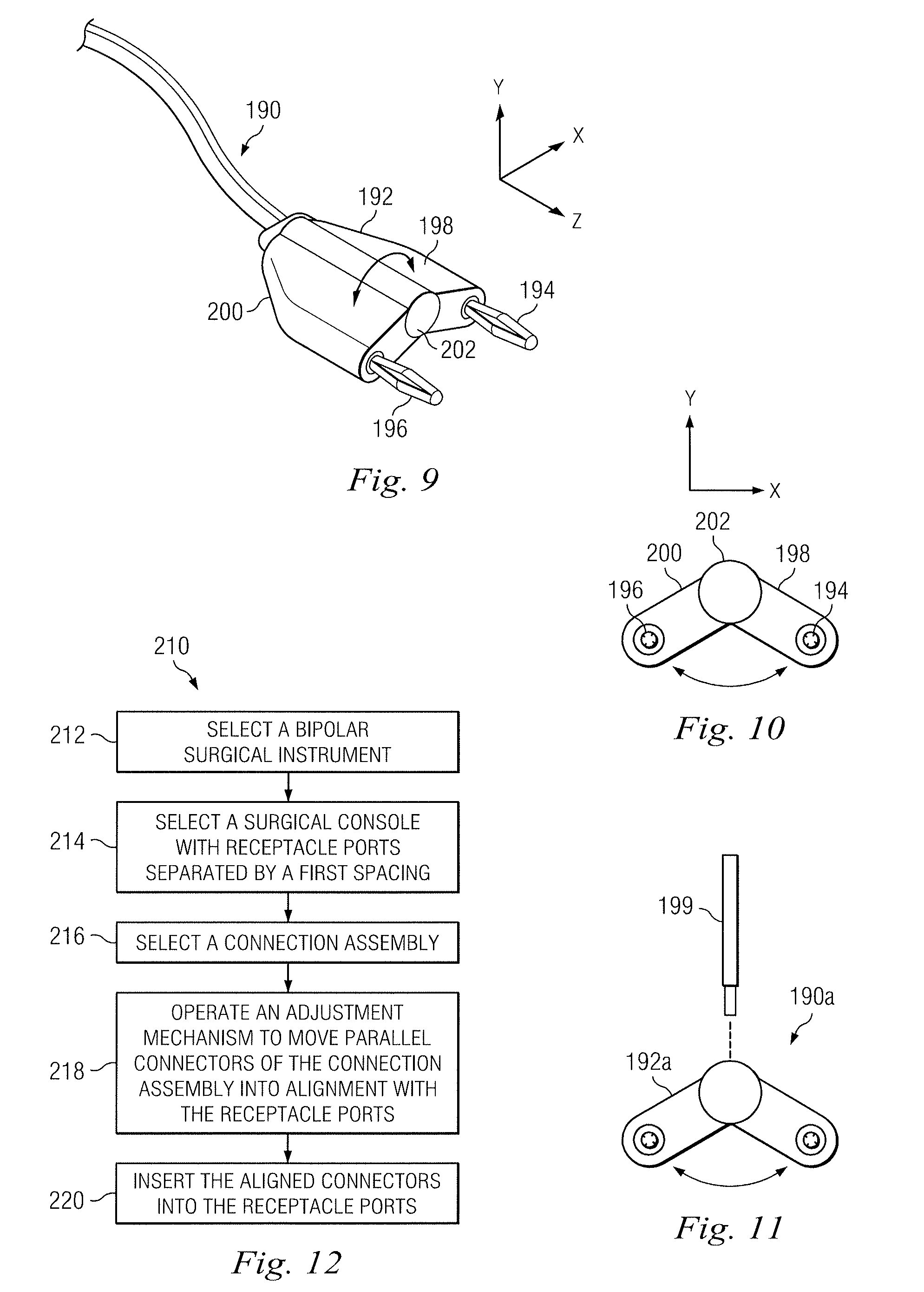
selecting a bipolar surgical instrument; selecting a first surgical console adapted for electrical connection to the bipolar surgical instrument, the first surgical console including a first set of paired receptacle ports separated by a first spacing; selecting a connection assembly, including a first elongated connector in parallel alignment with a second elongated connector and an adjustment mechanism, to interconnect the bipolar surgical instrument and the first surgical console; operating the adjustment mechanism to move the first elongated connector relative to the second elongated connector while maintaining parallel alignment between the elongated connectors until each of the elongated connectors is in alignment with one of the receptacle ports in the first set; and inserting each elongated connector into one of the receptacle ports of the first set to connect the bipolar surgical instrument to the first surgical console. 20. The method of 21. The method of removing the elongated connectors from the receptacle ports of the surgical console; selecting a second surgical console adapted for electrical connection to the bipolar surgical instrument, the second surgical console including a second set of paired receptacle ports separated by a second spacing different than the first spacing; operating the adjustment mechanism to move the first elongated connector relative to the second elongated connector while maintaining parallel alignment between the elongated connectors until each of the elongated connectors is in alignment with one of the receptacle ports in the second set; and inserting each elongated connector into one of the receptacle ports of the second set to connect the bipolar surgical instrument to the second surgical console. 22. The method of 23. The method of 24. The method of 25. The method of TECHNICAL FIELD
BACKGROUND
SUMMARY
BRIEF DESCRIPTION OF THE DRAWINGS
DETAILED DESCRIPTION