Thermal Transfer and Acoustic Matching Layers for Ultrasound Transducer
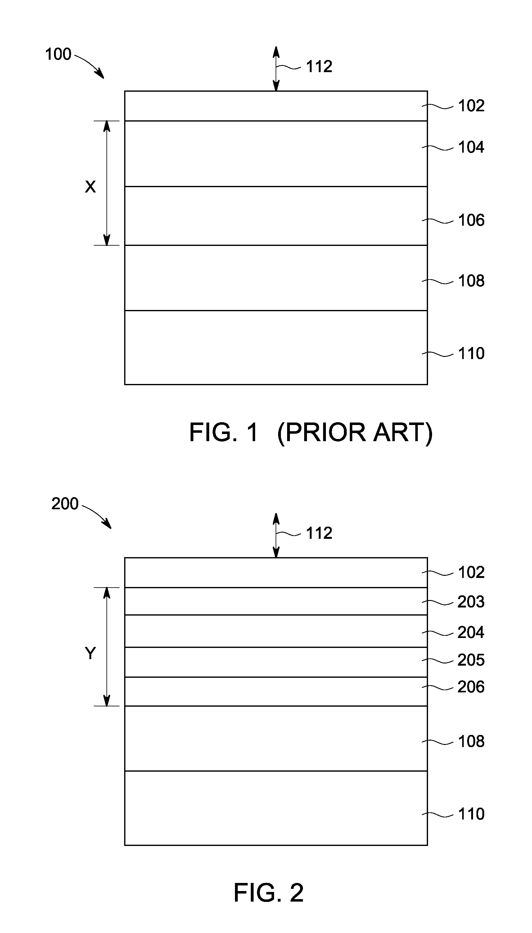
[Not Applicable] [Not Applicable] [Not Applicable] Embodiments of the present technology generally relate to ultrasound transducers configured to provide improved thermal characteristics. As depicted in Piezoelectric element 108 can convert electrical signals into ultrasound waves to be transmitted toward a target and can also convert received ultrasound waves into electrical signals. Arrows 112 depict ultrasound waves transmitted from and received at transducer 100. The received ultrasound waves can be used by the ultrasound system to create an image of the target. In order to increase energy out of transducer 100, impedance matching layers 104, 106 are disposed between piezoelectric element 108 and lens 102. Conventionally, optimal impedance matching has been believed to be achieved when matching layers 104, 106 separate piezoelectric element 108 and lens 102 by a distance x of about ¼ to ½ of the desired wavelength of transmitted ultrasound waves at the resonant frequency. Conventional belief is that such a configuration can keep ultrasound waves that were reflected within the matching layers 104, 106 in phase when they exit the matching layers 104, 106. Transmitting ultrasound waves from transducer 100 can heat lens 102. However, patient contact transducers have a maximum surface temperature of about 40 degrees Celsius in order to avoid patient discomfort and comply with regulatory temperature limits. Thus, lens temperature can be a limiting factor for wave transmission power and transducer performance. Many known thermal management techniques are focused on the backside of the transducer in order to minimize reflection of ultrasound energy toward the lens. Nonetheless, there is a need for improved ultrasound transducers with improved thermal characteristics. Embodiments of the present technology generally relate to ultrasound transducers and methods of making ultrasound transducers. In an embodiment, for example, an ultrasound transducer can include: a backing; a piezoelectric element attached to the backing, the piezoelectric element configured to convert electrical signals into ultrasound waves to be transmitted toward a target, the piezoelectric element configured to convert received ultrasound waves into electrical signals; a first matching layer attached to the piezoelectric element, the first matching layer having a first acoustic impedance and a thermal conductivity of about greater than 30 W/mK; and a second matching layer attached to the first matching layer, the second matching layer having a second acoustic impedance that is lower than the first acoustic impedance. In an embodiment, for example, the first acoustic impedance is about 10-20 MRayl. In an embodiment, for example, the first matching layer has a first thickness, and the second matching layer has a second thickness that is less than the first thickness. In an embodiment, for example, the second matching layer has a thermal conductivity of about 0.5-300 W/mK. In an embodiment, for example, an ultrasound transducer can further include a third matching layer attached to the second matching layer, the third matching layer having a third acoustic impedance that is lower than the second acoustic impedance. In an embodiment, for example, an ultrasound transducer can further include a lens, wherein the first and second matching layers are disposed between the piezoelectric element and the lens, and wherein the thickness of each matching layer is less than about ¼ of a desired wavelength of transmitted ultrasound waves at a resonant frequency. In an embodiment, for example, the first matching layer comprises a metal. In an embodiment, for example, the first matching layer includes a wing configured to extend beyond an end of the piezoelectric element to the backing, the wing configured to conduct heat from the piezoelectric element to the backing. In an embodiment, for example, the piezoelectric element includes a plurality of cuts, and wherein the wing is disposed substantially perpendicular to the cuts. In an embodiment, for example, the piezoelectric element includes a plurality of cuts, and wherein the wing is disposed substantially parallel to the cuts. In an embodiment, for example, the first matching layer includes a portion configured to extend beyond an end of the piezoelectric element, the portion being connected to a thermally conductive sheet configured to extend to the backing, the portion and the sheet configured to conduct heat from the piezoelectric element to the backing. In an embodiment, for example, the backing, the piezoelectric element, the first matching layer and the second matching layer are attached by epoxy. In an embodiment, for example, a method of making an ultrasound transducer can include: attaching a backing to a piezoelectric element, the piezoelectric element configured to convert electrical signals into ultrasound waves to be transmitted toward a target, the piezoelectric element configured to convert received ultrasound waves into electrical signals; attaching a first matching layer to the piezoelectric element, the first matching layer having a first acoustic impedance and a thermal conductivity of about greater than 30 W/mK; and attaching a second matching layer to the first matching layer, the second matching layer having a second acoustic impedance that is lower than the first acoustic impedance. In an embodiment, for example, a method of making an ultrasound transducer can further include: making a plurality of cuts in the piezoelectric element and the first and second matching layers. In an embodiment, for example, the first matching layer includes a wing configured to extend beyond an end of the piezoelectric element, and the method can further include: cutting a plurality of notches on a surface of the wing; and folding the wing away from the notches such that the wing extends beyond the end of the piezoelectric element to the backing, the wing configured to conduct heat from the piezoelectric element to the backing. In an embodiment, for example, the first matching layer includes a portion configured to extend beyond an end of the piezoelectric element, and the method can further include: connecting the portion to a thermally conductive sheet configured to extend to the backing, the portion and the sheet configured to conduct heat from the piezoelectric element to the backing. In an embodiment, for example, the backing, the piezoelectric element, the first matching layer and the second matching layer are attached using epoxy. In an embodiment, for example, an ultrasound transducer can include: a backing; a piezoelectric element attached to the backing, the piezoelectric element configured to convert electrical signals into ultrasound waves to be transmitted toward a target, the piezoelectric element configured to convert received ultrasound waves into electrical signals; a lens; and a matching layer disposed between the piezoelectric element and the lens, the matching layer configured to conduct heat from the piezoelectric element to the backing. The foregoing summary, as well as the following detailed description of certain embodiments, will be better understood when read in conjunction with the appended drawings. For the purpose of illustrating the invention, certain embodiments are shown in the drawings. It should be understood, however, that the present invention is not limited to the arrangements and instrumentality shown in the attached drawings. Embodiments of the present technology generally relate to ultrasound transducers configured to provide improved thermal characteristics. In the drawings, like elements are identified with like identifiers. As with conventional ultrasound transducers, piezoelectric element 108 can convert electrical signals into ultrasound waves to be transmitted toward a target and can also convert received ultrasound waves into electrical signals. Arrows 112 depict ultrasound waves transmitted from and received at transducer 200. The received ultrasound waves can be used by the ultrasound system to create an image of the target. In order to increase energy out of transducer 100, impedance matching layers 203-206 are disposed between piezoelectric element 108 and lens 102. Matching layers 203-206 separate piezoelectric element 108 and lens 102 by a distance y that can be less than or greater than the distance x (which distance is about ¼ to ½ of the desired wavelength of transmitted ultrasound waves at the resonant frequency). As depicted in Matching layer 205, which is disposed between matching layer 206 and matching layer 204, can comprise a material with an acoustic impedance of about 5-15 MRayl and thermal conductivity of about 1-300 W/mK. Matching layer 205 can have a thickness of less than about 0.25λ. In certain embodiments, matching layer 205 can comprise a metal(s), such as copper, copper alloy, copper with graphite pattern embedded therein, magnesium, magnesium alloy, aluminum (plate or bar), aluminum alloy, filled epoxy, glass ceramic, composite ceramic, and/or macor, for example. Matching layer 204, which is disposed between matching layer 205 and matching layer 203, can comprise a material with an acoustic impedance of about 2-8 MRayl and thermal conductivity of about 0.5-50 W/mK. Matching layer 204 can have a thickness of less than about 0.25λ. In certain embodiments, matching layer 204 can comprise a non-metal, such as an epoxy with fillers, such as silica fillers, for example. In certain embodiments, matching layer 204 can comprise a graphite type material, for example. Non-metals, such as an epoxy with fillers can have a relatively low acoustic impedance such that ultrasound waves travel through the layer at a lower velocity, thereby requiring a thinner matching layer to achieve desired acoustic characteristics. Matching layer 203, which is disposed between matching layer 204 and lens 102, can comprise a material with an acoustic impedance of about 1.5-3 MRayl and thermal conductivity of about 0.5-50 W/mK. Matching layer 203 can have a thickness of less than about 0.25λ. In certain embodiments, matching layer 203 can comprise a non-metal, such as plastic and/or an epoxy with fillers, such as silica fillers, for example. In an embodiment, acoustic impedance of matching layers 203-206 decreases as the matching layers 203-206 increase in distance from piezoelectric element 108. That is, matching layer 206 can have a higher acoustic impedance than matching layer 205, matching layer 205 can have a higher acoustic impedance than matching layer 204, and matching layer 204 can have a higher acoustic impedance than matching layer 203. It has been found that providing three or more matching layers with acoustic impedances that decrease in this manner can provide improved acoustic properties, such as increased sensitivity and/or increased border bandwidth, for example. Such improved acoustic properties can improve detection of structures in a target, such as a human body, for example. In an embodiment, thermal conductivity of matching layers 205, 206 is greater than thermal conductivity of matching layers 203, 204. It has been found that disposing a matching layer with a relatively high thermal conductivity (such as matching layers 205 and/or 206, for example) near piezoelectric element 108 can provide for improved thermal characteristics. For example, such matching layers can dissipate heat generated by piezoelectric element 108 more readily than matching layers of lower thermal conductivity such as matching layers 203 and 204, for example. Wings 402 can be formed by providing matching layer 401 such that it extends beyond the ends of piezoelectric element 108. A plurality of notches 403 can be provided in a surface of matching layer 401, and the portions of matching layer 401 that extend beyond the ends of piezoelectric element 108 can be folded away from notches 403 toward piezoelectric element 108 and backing 110 such that the notches 403 are disposed at and/or around outer elbows of the folds as shown in Wings 402 are configured to conduct heat from piezoelectric element 108 to a heat sink and/or thermal management at backing 110. The relatively high thermal conductivity of matching layer 401 and wings 402 can aid in the desired heat transfer toward the backing 110 of transducer 400, and away from lens 102. Wings 402 can also form a ground for transducer 400 by connecting to the appropriate grounding circuit such as a flexible circuit that are usually placed between piezoelectric element 108 and backing 110. Wings 402 can also act as an electrical shielding for the transducer 400. Simulation studies can be used to optimize matching layer characteristics such that matching layers with desired acoustic impedance and thermal conductivity are provided with minimal thickness, thereby allowing cutting operations to be performed more effectively. In certain embodiments, the techniques described herein can be applied in connection with one-dimensional linear array transducers, two-dimensional transducers and/or annular array transducers. In certain embodiments, the techniques described herein can be applied in connection with a transducer of any geometry. Applying the techniques herein can provide a technical effect of improving acoustic properties and/or thermal characteristics. For example, directing heat away from a transducer lens can allow the transducer to be used at increased power levels, thereby improving signal quality and image quality. The inventions described herein extend not only to the transducers described herein, but also to methods of making such transducers. While the inventions have been described with reference to embodiments, it will be understood by those skilled in the art that various changes may be made and equivalents may be substituted without departing from the scope of the inventions. In addition, many modifications may be made to adapt a particular situation or material to the teachings of the inventions without departing from their scope. Therefore, it is intended that the inventions not be limited to the particular embodiments disclosed, but that the inventions will include all embodiments falling within the scope of the appended claims. Ultrasound transducers and methods of making ultrasound transducers with improved thermal characteristics are provided. An ultrasound transducer can include: a backing, a piezoelectric element attached to the backing, a first matching layer attached to the piezoelectric element, and a second matching layer attached to the first matching layer. The first matching layer can comprise metal and can have a thermal conductivity of about greater than 30 W/mK. The second matching layer can have a thermal conductivity of about 0.5-300 W/mK. The first matching layer can have an acoustic impedance of about 10-20 MRayl, and the second matching layer can have a lower acoustic impedance. The first matching layer can be thicker than the second matching layer. The ultrasound transducer can include a lens and a matching layer disposed between the piezoelectric element and the lens can be configured to conduct heat from the piezoelectric element to the backing. 1. An ultrasound transducer comprising:
a backing; a piezoelectric element attached to the backing, the piezoelectric element configured to convert electrical signals into ultrasound waves to be transmitted toward a target, the piezoelectric element configured to convert received ultrasound waves into electrical signals; a first matching layer attached to the piezoelectric element, the first matching layer having a first acoustic impedance and a thermal conductivity of about greater than 30 W/mK; and a second matching layer attached to the first matching layer, the second matching layer having a second acoustic impedance that is lower than the first acoustic impedance. 2. The ultrasound transducer of 3. The ultrasound transducer of 4. The ultrasound transducer of 5. (canceled) 6. The ultrasound transducer of a third matching layer attached to the second matching layer, the third matching layer having a third acoustic impedance that is lower than the second acoustic impedance. 7. The ultrasound transducer of a lens, wherein the first and second matching layers are disposed between the piezoelectric element and the lens, and wherein the thickness of each matching layer is less than about ¼ of a desired wavelength of transmitted ultrasound waves at a resonant frequency. 8. The ultrasound transducer of 9. The ultrasound transducer of 10. The ultrasound transducer of 11. The ultrasound transducer of 12. The ultrasound transducer of 13. The ultrasound transducer of 14. A method of making an ultrasound transducer comprising:
attaching a backing to a piezoelectric element, the piezoelectric element configured to convert electrical signals into ultrasound waves to be transmitted toward a target, the piezoelectric element configured to convert received ultrasound waves into electrical signals; attaching a first matching layer to the piezoelectric element, the first matching layer having a first acoustic impedance and a thermal conductivity of about greater than 30 W/mK; and attaching a second matching layer to the first matching layer, the second matching layer having a second acoustic impedance that is lower than the first acoustic impedance. 15. The method of making a plurality of cuts in the piezoelectric element and the first and second matching layers. 16. The method of cutting a plurality of notches on a surface of the wing; and folding the wing away from the notches such that the wing extends beyond the end of the piezoelectric element to the backing, the wing configured to conduct heat from the piezoelectric element to the backing. 17. The method of connecting the portion to a thermally conductive sheet configured to extend to the backing, the portion and the sheet configured to conduct heat from the piezoelectric element to the backing. 18. The method of 19. An ultrasound transducer comprising:
a backing; a piezoelectric element attached to the backing, the piezoelectric element configured to convert electrical signals into ultrasound waves to be transmitted toward a target, the piezoelectric element configured to convert received ultrasound waves into electrical signals; a lens; and a matching layer disposed between the piezoelectric element and the lens, the matching layer configured to conduct heat from the piezoelectric element to the backing. 20. The ultrasound transducer of RELATED APPLICATIONS
FEDERALLY SPONSORED RESEARCH OR DEVELOPMENT
MICROFICHE/COPYRIGHT REFERENCE
BACKGROUND OF THE INVENTION
BRIEF SUMMARY OF THE INVENTION
BRIEF DESCRIPTION OF THE DRAWINGS
DETAILED DESCRIPTION OF CERTAIN EMBODIMENTS