Zoom Lens System, Interchangeable Lens Apparatus and Camera System
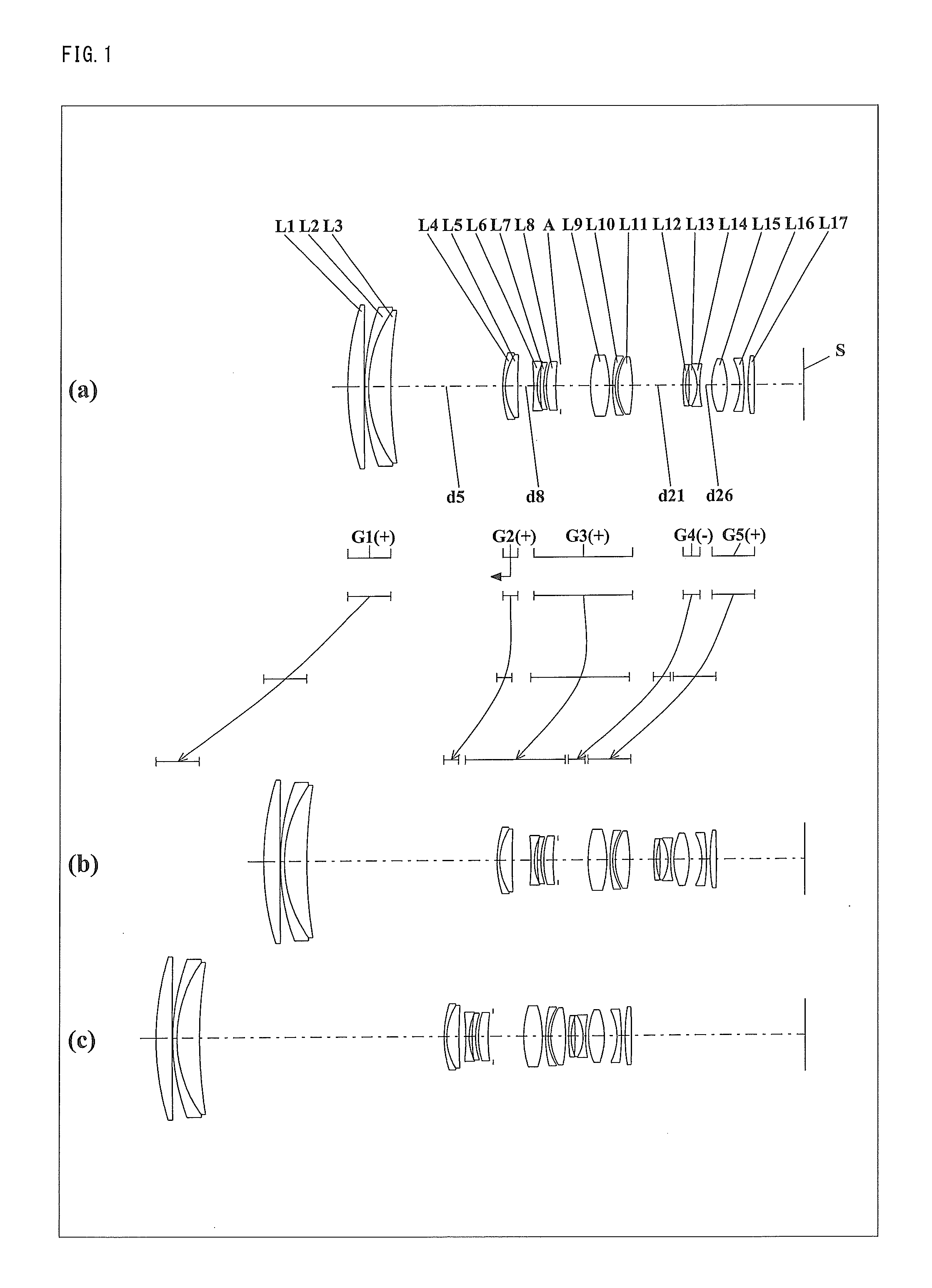
This application is based on application No. 2010-204174 filed in Japan on Sep. 13, 2010 and application No. 2011-151047 filed in Japan on Jul. 7, 2011, the contents of which are hereby incorporated by reference. 1. Field of the Invention The present invention relates to a zoom lens system, an interchangeable lens apparatus, and a camera system. In particular, the present invention relates to: a zoom lens system which is suitable as an imaging lens system in, so-called, an interchangeable-lens type digital camera system; and an interchangeable lens apparatus and a camera system each employing this zoom lens system. 2. Description of the Background Art In recent years, interchangeable-lens type digital camera systems have been spreading rapidly. Such interchangeable-lens type digital camera systems (also referred to simply as “camera systems”, hereinafter) include: a camera body having an image sensor such as a CCD (Charge Coupled Device), a CMOS (Complementary Metal-Oxide Semiconductor) or the like; and an interchangeable lens apparatus having an imaging lens system for forming an optical image on a light receiving surface of the image sensor. Such interchangeable-lens type digital camera systems are able to take a high-sensitive and high-quality image because an image sensor used in the interchangeable-lens type digital camera systems is larger than that equipped for a compact type digital camera. In addition, the interchangeable-lens type digital camera systems can realize: high-speed focusing and high-speed image processing after image taking; and easy replacement of an interchangeable lens apparatus in accordance with a desired scene. Furthermore, an interchangeable lens apparatus having a zoom lens system that forms an optical image with variable magnification is popular because it allows free change of focal length without the necessity of lens replacement. Accordingly, for some time, various kinds of zoom lens systems have been proposed, which can be utilized as an imaging lens system in the interchangeable-lens type digital camera systems, such as a zoom lens system disclosed in each of Japanese Laid-Open Patent Publications No. 2004-094056, No. 2003-107353, No. 04-338910, and No. 06-118305. Although the interchangeable-lens type digital camera systems show the above-mentioned various kinds of merits, the size and the weight of such interchangeable-lens type digital camera systems are greater than those of a compact type digital camera. It is preferable that the size and the weight of the interchangeable-lens type digital camera systems are as small as possible for easy carrying around and handling. Accordingly, a most compact and lightweight possible zoom lens system with maintaining imaging performance is desired as a zoom lens system to be used in the interchangeable-lens type digital camera systems. One object of the present invention is to provide a compact and lightweight zoom lens system having excellent imaging performance, which can be suitably used in an interchangeable-lens type digital camera system. Another object of the present invention is to provide compact and lightweight interchangeable lens apparatus and camera system. The novel concepts disclosed herein were achieved in order to solve the foregoing problems in the conventional art, and herein is disclosed: a zoom lens system having a plurality of lens units, each lens unit being composed of at least one lens element, the zoom lens system, in order from an object side to an image side, comprising: a first lens unit having positive optical power; a second lens unit having positive optical power; and at least two subsequent lens units, wherein the first lens unit moves along an optical axis at the time of zooming from a wide-angle limit to a telephoto limit, an interval between the second lens unit and a lens unit which is one of the at least two subsequent lens units varies at the time of zooming or at the time of focusing from an infinity in-focus condition to a close-object in-focus condition, the first lens unit is composed of at least three lens elements, each of the first lens unit and the second lens unit includes at least one lens element having negative optical power, and the following conditions (1) and (2) are satisfied: where vdMINis the minimum value among Abbe numbers to the d-line of each lens element constituting the first lens unit, vdMAXis the maximum value among Abbe numbers to the d-line of each lens element constituting the first lens unit, m is the maximum value among the amounts of movement of each subsequent lens unit at the time of zooming from a wide-angle limit to a telephoto limit, fTis a focal length of the entire system at a telephoto limit, and fWis a focal length of the entire system at a wide-angle limit. The novel concepts disclosed herein were achieved in order to solve the foregoing problems in the conventional art, and herein is disclosed: an interchangeable lens apparatus comprising: a zoom lens system; and a lens mount section which is connectable to a camera body including an image sensor for receiving an optical image formed by the zoom lens system and converting the optical image into an electric image signal; wherein the zoom lens system, having a plurality of lens units, each lens unit being composed of at least one lens element, in order from an object side to an image side, comprises: a first lens unit having positive optical power; a second lens unit having positive optical power; and at least two subsequent lens units, wherein the first lens unit moves along an optical axis at the time of zooming from a wide-angle limit to a telephoto limit, an interval between the second lens unit and a lens unit which is one of the at least two subsequent lens units varies at the time of zooming or at the time of focusing from an infinity in-focus condition to a close-object in-focus condition, the first lens unit is composed of at least three lens elements, each of the first lens unit and the second lens unit includes at least one lens element having negative optical power, and the following conditions (1) and (2) are satisfied: where vdMINis the minimum value among Abbe numbers to the d-line of each lens element constituting the first lens unit, vdMAXis the maximum value among Abbe numbers to the d-line of each lens element constituting the first lens unit, m is the maximum value among the amounts of movement of each subsequent lens unit at the time of zooming from a wide-angle limit to a telephoto limit, fTis a focal length of the entire system at a telephoto limit, and fWis a focal length of the entire system at a wide-angle limit. The novel concepts disclosed herein were achieved in order to solve the foregoing problems in the conventional art, and herein is disclosed: a camera system comprising: an interchangeable lens apparatus including a zoom lens system; and a camera body which is detachably connected to the interchangeable lens apparatus via a camera mount section, and includes an image sensor for receiving an optical image formed by the zoom lens system and converting the optical image into an electric image signal; wherein the zoom lens system, having a plurality of lens units, each lens unit being composed of at least one lens element, in order from an object side to an image side, comprises: a first lens unit having positive optical power; a second lens unit having positive optical power; and at least two subsequent lens units, wherein the first lens unit moves along an optical axis at the time of zooming from a wide-angle limit to a telephoto limit, an interval between the second lens unit and a lens unit which is one of the at least two subsequent lens units varies at the time of zooming or at the time of focusing from an infinity in-focus condition to a close-object in-focus condition, the first lens unit is composed of at least three lens elements, each of the first lens unit and the second lens unit includes at least one lens element having negative optical power, and the following conditions (1) and (2) are satisfied: where vdMINis the minimum value among Abbe numbers to the d-line of each lens element constituting the first lens unit, vdMAXis the maximum value among Abbe numbers to the d-line of each lens element constituting the first lens unit, m is the maximum value among the amounts of movement of each subsequent lens unit at the time of zooming from a wide-angle limit to a telephoto limit, fTis a focal length of the entire system at a telephoto limit, and fWis a focal length of the entire system at a wide-angle limit. According to the present invention, it is possible to provide: a compact and lightweight zoom lens system having excellent imaging performance; and an interchangeable lens apparatus and a camera system each employing this zoom lens system. This and other objects and features of this invention will become clear from the following description, taken in conjunction with the preferred embodiments with reference to the accompanied drawings in which: In each Fig., part (a) shows a lens configuration at a wide-angle limit (in the minimum focal length condition: focal length fw), part (b) shows a lens configuration at a middle position (in an intermediate focal length condition: focal length fM=√(fW*fT)), and part (c) shows a lens configuration at a telephoto limit (in the maximum focal length condition: focal length fT). Further, in each Fig., an arrow of straight or curved line provided between part (a) and part (b) indicates the movement of each lens unit from a wide-angle limit through a middle position to a telephoto limit. Moreover, in each Fig., an arrow imparted to a lens unit indicates focusing from an infinity in-focus condition to a close-object in-focus condition. That is, the arrow indicates the moving direction at the time of focusing from an infinity in-focus condition to a close-object in-focus condition. In each Fig., symbol (+) or (−) imparted to the symbol of each lens unit corresponds to the sign of the optical power of the lens unit. In each Fig., the straight line located on the most right-hand side indicates the position of the image surface S. As shown in Each of the zoom lens systems according to Embodiments 1, 4, and 5, in order from the object side to the image side, comprises a first lens unit G1 having positive optical power, a second lens unit G2 having positive optical power, and subsequent lens units, that is, a third lens unit G3, a fourth lens unit G4, and a fifth lens unit G5. Further, Each of the zoom lens systems according to Embodiments 2, 3, and 6, in order from the object side to the image side, comprises a first lens unit G1 having positive optical power, a second lens unit G2 having positive optical power, and subsequent lens units, that is, a third lens unit G3, a fourth lens unit G4, a fifth lens unit G5, and a sixth lens unit G6. The first lens unit G1, in order from the object side to the image side, comprises: a positive meniscus first lens element L1 with the convex surface facing the object side; a negative meniscus second lens element L2 with the convex surface facing the object side; and a positive meniscus third lens element L3 with the convex surface facing the object side. The second lens element L2 and the third lens element L3 are cemented with each other. The second lens unit G2, in order from the object side to the image side, comprises: a negative meniscus fourth lens element L4 with the convex surface facing the object side; and a positive meniscus fifth lens element L5 with the convex surface facing the object side. The fourth lens element L4 and the fifth lens element L5 are cemented with each other. The third lens unit G3, in order from the object side to the image side, comprises: a bi-concave sixth lens element L6; a negative meniscus seventh lens element L7 with the convex surface facing the object side; a positive meniscus eighth lens element L8 with the convex surface facing the object side; an aperture diaphragm A; a bi-convex ninth lens element L9; a negative meniscus tenth lens element L10 with the convex surface facing the object side; and a bi-convex eleventh lens element L11. The fourth lens unit G4, in order from the object side to the image side, comprises: a negative meniscus twelfth lens element L12 with the convex surface facing the object side; a positive meniscus thirteenth lens element L13 with the convex surface facing the image side; and a bi-concave fourteenth lens element L14. The thirteenth lens element L13 and the fourteenth lens element L14 are cemented with each other. The fifth lens unit G5, in order from the object side to the image side, comprises: a bi-convex fifteenth lens element L15; a negative meniscus sixteenth lens element L16 with the convex surface facing the image side; and a bi-convex seventeenth lens element L17. The first lens unit G1, in order from the object side to the image side, comprises: a planer-convex first lens element L1 with the convex surface facing the object side; a negative meniscus second lens element L2 with the convex surface facing the object side; and a positive meniscus third lens element L3 with the convex surface facing the object side. The second lens element L2 and the third lens element L3 are cemented with each other. The second lens unit G2, in order from the object side to the image side, comprises: a negative meniscus fourth lens element L4 with the convex surface facing the object side; and a positive meniscus fifth lens element L5 with the convex surface facing the object side. The fourth lens element L4 and the fifth lens element L5 are cemented with each other. The third lens unit G3, in order from the object side to the image side, comprises: a bi-concave sixth lens element L6; a bi-convex seventh lens element L7; a bi-concave eighth lens element L8; and an aperture diaphragm A. The seventh lens element L7 and the eighth lens element L8 are cemented with each other. The fourth lens unit G4, in order from the object side to the image side, comprises: a bi-convex ninth lens element L9; a negative meniscus tenth lens element L10 with the convex surface facing the object side; and a bi-convex eleventh lens element L11. The tenth lens element L10 and the eleventh lens element L11 are cemented with each other. The fifth lens unit G5, in order from the object side to the image side, comprises: a negative meniscus twelfth lens element L12 with the convex surface facing the object side; a positive meniscus thirteenth lens element L13 with the convex surface facing the image side; and a bi-concave fourteenth lens element L14. The thirteenth lens element L13 and the fourteenth lens element L14 are cemented with each other. The sixth lens unit G6, in order from the object side to the image side, comprises: a bi-convex fifteenth lens element L15; a negative meniscus sixteenth lens element L16 with the convex surface facing the image side; and a positive meniscus seventeenth lens element L17 with the convex surface facing the object side. The first lens unit G1, in order from the object side to the image side, comprises: a planer-convex first lens element L1 with the convex surface facing the object side; a negative meniscus second lens element L2 with the convex surface facing the object side; and a positive meniscus third lens element L3 with the convex surface facing the object side. The second lens element L2 and the third lens element L3 are cemented with each other. The second lens unit G2, in order from the object side to the image side, comprises: a negative meniscus fourth lens element L4 with the convex surface facing the object side; and a positive meniscus fifth lens element L5 with the convex surface facing the object side. The fourth lens element L4 and the fifth lens element L5 are cemented with each other. The third lens unit G3, in order from the object side to the image side, comprises: a bi-concave sixth lens element L6; a positive meniscus seventh lens element L7 with the convex surface facing the object side; a negative meniscus eighth lens element L8 with the convex surface facing the object side; and an aperture diaphragm A. The seventh lens element L7 and the eighth lens element L8 are cemented with each other. The fourth lens unit G4, in order from the object side to the image side, comprises: a bi-convex ninth lens element L9; a negative meniscus tenth lens element L10 with the convex surface facing the object side; and a bi-convex eleventh lens element L11. The tenth lens element L10 and the eleventh lens element L11 are cemented with each other. The fifth lens unit G5, in order from the object side to the image side, comprises: a negative meniscus twelfth lens element L12 with the convex surface facing the object side; a positive meniscus thirteenth lens element L13 with the convex surface facing the image side; and a bi-concave fourteenth lens element L14. The thirteenth lens element L13 and the fourteenth lens element L14 are cemented with each other. The sixth lens unit G6, in order from the object side to the image side, comprises: a bi-convex fifteenth lens element L15; a negative meniscus sixteenth lens element L16 with the convex surface facing the image side; and a positive meniscus seventeenth lens element L17 with the convex surface facing the object side. The first lens unit G1, in order from the object side to the image side, comprises: a planer-convex first lens element L1 with the convex surface facing the object side; a negative meniscus second lens element L2 with the convex surface facing the object side; and a positive meniscus third lens element L3 with the convex surface facing the object side. The second lens element L2 and the third lens element L3 are cemented with each other. The second lens unit G2, in order from the object side to the image side, comprises: a negative meniscus fourth lens element L4 with the convex surface facing the object side; and a planer-convex fifth lens element L5 with the convex surface facing the object side. The fourth lens element L4 and the fifth lens element L5 are cemented with each other. The third lens unit G3, in order from the object side to the image side, comprises: a bi-concave sixth lens element L6; a bi-convex seventh lens element L7; a bi-concave eighth lens element L8; an aperture diaphragm A; a bi-convex ninth lens element L9; a negative meniscus tenth lens element L10 with the convex surface facing the object side; and a bi-convex eleventh lens element L11. The seventh lens element L7 and the eighth lens element L8 are cemented with each other, and the tenth lens element L10 and the eleventh lens element L11 are cemented with each other. The fourth lens unit G4, in order from the object side to the image side, comprises: a negative meniscus twelfth lens element L12 with the convex surface facing the object side; a positive meniscus thirteenth lens element L13 with the convex surface facing the image side; and a bi-concave fourteenth lens element L14. The thirteenth lens element L13 and the fourteenth lens element L14 are cemented with each other. The fifth lens unit G5, in order from the object side to the image side, comprises: a bi-convex fifteenth lens element L15; a negative meniscus sixteenth lens element L16 with the convex surface facing the image side; and a bi-convex seventeenth lens element L17. The first lens unit G1, in order from the object side to the image side, comprises: a bi-convex first lens element L1; a negative meniscus second lens element L2 with the convex surface facing the object side; and a positive meniscus third lens element L3 with the convex surface facing the object side. The second lens element L2 and the third lens element L3 are cemented with each other. The second lens unit G2, in order from the object side to the image side, comprises: a negative meniscus fourth lens element L4 with the convex surface facing the object side; and a positive meniscus fifth lens element L5 with the convex surface facing the object side. The fourth lens element L4 and the fifth lens element L5 are cemented with each other. The third lens unit G3, in order from the object side to the image side, comprises: a bi-concave sixth lens element L6; a positive meniscus seventh lens element L7 with the convex surface facing the object side; and a bi-concave eighth lens element L8. The sixth lens element L6 and the seventh lens element L7 are cemented with each other The fourth lens unit G4, in order from the object side to the image side, comprises: an aperture diaphragm A; a bi-convex ninth lens element L9; a planer-concave tenth lens element L10 with the concave surface facing the image side; a bi-convex eleventh lens element L11; and a positive meniscus twelfth lens element L12 with the convex surface facing the object side. The fifth lens unit G5, in order from the object side to the image side, comprises: a negative meniscus thirteenth lens element L13 with the convex surface facing the object side; a positive meniscus fourteenth lens element L14 with the convex surface facing the image side; a bi-concave fifteenth lens element L15; a bi-convex sixteenth lens element L16; a negative meniscus seventeenth lens element L17 with the convex surface facing the image side; and a positive meniscus eighteenth lens element L18 with the convex surface facing the image side. The fourteenth lens element L14 and the fifteenth lens element L15 are cemented with each other. The first lens unit G1, in order from the object side to the image side, comprises: a planer-convex first lens element L1 with the convex surface facing the object side; a negative meniscus second lens element L2 with the convex surface facing the object side; and a positive meniscus third lens element L3 with the convex surface facing the object side. The second lens element L2 and the third lens element L3 are cemented with each other. The second lens unit G2, in order from the object side to the image side, comprises: a negative meniscus fourth lens element L4 with the convex surface facing the object side; and a positive meniscus fifth lens element L5 with the convex surface facing the object side. The fourth lens element L4 and the fifth lens element L5 are cemented with each other. The third lens unit G3, in order from the object side to the image side, comprises: a bi-concave sixth lens element L6; a bi-convex seventh lens element L7; a bi-concave eighth lens element L8; and an aperture diaphragm A. The seventh lens element L7 and the eighth lens element L8 are cemented with each other. The fourth lens unit G4, in order from the object side to the image side, comprises: a bi-convex ninth lens element L9; a negative meniscus tenth lens element L10 with the convex surface facing the object side; and a bi-convex eleventh lens element L11. The tenth lens element L10 and the eleventh lens element L11 are cemented with each other. The fifth lens unit G5, in order from the object side to the image side, comprises: a negative meniscus twelfth lens element L12 with the convex surface facing the object side; a positive meniscus thirteenth lens element L13 with the convex surface facing the image side; and a bi-concave fourteenth lens element L14. The thirteenth lens element L13 and the fourteenth lens element L14 are cemented with each other. The sixth lens unit G6, in order from the object side to the image side, comprises: a bi-convex fifteenth lens element L15; a negative meniscus sixteenth lens element L16 with the convex surface facing the image side; and a positive meniscus seventeenth lens element L17 with the convex surface facing the object side. In the zoom lens systems according to Embodiments 1, 4, and 5, at the time of zooming from a wide-angle limit to a telephoto limit, the second lens unit G2 in the zoom lens system according to Embodiment 5 moves to the image side along the optical axis while each of the lens units other than this second lens unit G5 moves to the object side along the optical axis so that the interval between the first lens unit G1 and the second lens unit G2 is longer at a telephoto limit than at a wide-angle limit, the interval between the second lens unit G2 and the third lens unit G3 is shorter at a telephoto limit than at a wide-angle limit, the interval between the third lens unit G3 and the fourth lens unit G4 is shorter at a telephoto limit than at a wide-angle limit, and the interval between the fourth lens unit G4 and the fifth lens unit G5 is shorter at a telephoto limit than at a wide-angle limit. In the zoom lens systems according to Embodiments 2 and 3, at the time of zooming from a wide-angle limit to a telephoto limit, each of the lens units moves to the object side along the optical axis so that the interval between the first lens unit G1 and the second lens unit G2 is longer at a telephoto limit than at a wide-angle limit, the interval between the second lens unit G2 and the third lens unit G3 is shorter at a telephoto limit than at a wide-angle limit, the interval between the third lens unit G3 and the fourth lens unit G4 is shorter at a telephoto limit than at a wide-angle limit, the interval between the fourth lens unit G4 and the fifth lens unit G5 is shorter at a telephoto limit than at a wide-angle limit, and the interval between the fifth lens unit G5 and the sixth lens unit G6 is shorter at a telephoto limit than at a wide-angle limit. In the zoom lens system according to Embodiment 6, at the time of zooming from a wide-angle limit to a telephoto limit, each of the lens units moves to the object side along the optical axis so that the interval between the first lens unit G1 and the second lens unit G2 is longer at a telephoto limit than at a wide-angle limit, the interval between the second lens unit G2 and the third lens unit G3 at a telephoto limit is equal to the interval at a wide-angle limit, the interval between the third lens unit G3 and the fourth lens unit G4 is longer at a telephoto limit than at a wide-angle limit, the interval between the fourth lens unit G4 and the fifth lens unit G5 is shorter at a telephoto limit than at a wide-angle limit, and the interval between the fifth lens unit G5 and the sixth lens unit G6 is shorter at a telephoto limit than at a wide-angle limit. Particularly, the interval between the second lens unit G2 and the third lens unit G3 does not vary at the time of zooming from a wide-angle limit to a telephoto limit, while the interval varies only at the time of focusing from an infinity in-focus condition to a close-object in-focus condition. In the zoom lens systems according to Embodiments 1 to 4, and 6, the aperture diaphragm A moves together with the third lens unit G3 along the optical axis. In the zoom lens system according to Embodiment 5, the aperture diaphragm A moves together with the fourth lens unit G4 along the optical axis. Also, in the zoom lens systems according to Embodiments 1 to 6, each of the lens units individually moves along the optical axis at the time of zooming or at the time of focusing. Each of the zoom lens systems according to Embodiments 1 to 6 comprises the first lens unit G1 having positive optical power, the second lens unit G2 having positive optical power, and at least two subsequent lens units. In the zoom lens systems according to Embodiments 1 to 6, light passing through the optical system is converged by the first lens unit G1 having positive optical power, and thereby the height of an incident light beam to the second lens unit G2 and the subsequent lens units can be reduced. As a result, the size and the weight of a focusing lens unit in a zoom lens system which adopts an inner-focus method can be reduced. Moreover, because the first lens unit G1 moves along the optical axis at the time of zooming from a wide-angle limit to a telephoto limit, the size and the weight of the focusing lens unit in the zoom lens system which adopts an inner-focus method can be more effectively reduced. In the zoom lens systems according to Embodiments 1 to 6, because the interval between the second lens unit G2 and a lens unit which is one of the at least two subsequent lens units varies at the time of zooming from a wide-angle limit to a telephoto limit or at the time of focusing from an infinity in-focus condition to a close-object in-focus condition, aberration fluctuation occurred at the time of zooming or at the time of focusing can be suppressed, and excellent optical performance can be maintained. In the zoom lens systems according to Embodiments 1 to 6, because the first lens unit G1 is composed of at least three lens elements, chromatic aberration and spherical aberration are compensated simultaneously all over the zooming region. In the zoom lens systems according to Embodiments 1 to 6, because each of the first lens unit G1 and the second lens unit G2 includes at least one lens element having negative optical power, chromatic aberration fluctuation occurred at the time of zooming can be suppressed, and aberration fluctuation occurred at the time of focusing can be compensated simultaneously. In the zoom lens systems according to Embodiments 1 to 6, the aperture diaphragm A is arranged in a lens unit which is one of the at least two subsequent lens units, and a lens unit located on the object side relative to the aperture diaphragm A performs focusing from an infinity in-focus condition to a close-object in-focus condition. Therefore, aberration fluctuation due to variation from an infinity in-focus condition to a close-object in-focus condition can be sufficiently suppressed. In the zoom lens systems according to Embodiments 1 to 4, and 6, the second lens unit G2 located on the object side relative to the aperture diaphragm A moves to the object side along the optical axis at the time of focusing from an infinity in-focus condition to a close-object in-focus condition. In the zoom lens systems according to Embodiments 1 to 4, and 6, the weight of a focusing lens unit can be reduced because the second lens unit G2 is composed of two lens elements. In addition, it is preferable that the second lens unit G2 which is the focusing lens unit is solely composed of a cemented lens element. In this case, chromatic aberration at a telephoto limit during focusing can be suitably compensated. In the zoom lens system according to Embodiment 5, the third lens unit G3 located on the object side relative to the aperture diaphragm A moves to the image side along the optical axis at the time of focusing from an infinity in-focus condition to a close-object in-focus condition. In the zoom lens system according to Embodiment 5, excellent optical performance on a close-object in-focus condition can be maintained because the third lens unit G3 is composed of at least two lens elements. In addition, it is preferable that the third lens unit G3 which is the focusing lens unit has negative optical power. In this case, the weight and the size along a diameter of the focusing lens unit can be reduced. In the zoom lens systems according to Embodiments 1 to 6, the aperture diaphragm A is arranged in the lens unit which is one of the at least two subsequent lens units. A lens unit located on the image side relative to the aperture diaphragm A is moved in a direction perpendicular to the optical axis in order to optically compensate image blur caused by vibration of an optical system, and thereby excellent optical performance during image blur compensation can be maintained. Specifically, in the zoom lens systems according to Embodiments 1 and 4, an entirety of the fourth lens unit G4 is moved in a direction perpendicular to the optical axis in order to optically compensate image blur. In the zoom lens systems according to Embodiments 2, 3, and 6, an entirety of the fifth lens unit G5 is moved in a direction perpendicular to the optical axis in order to optically compensate image blur. In the zoom lens system according to Embodiment 5, a part of the fifth lens unit G5 (the thirteenth lens element L13, the fourteenth lens element L14, and the fifteenth lens element L15) is moved in a direction perpendicular to the optical axis in order to optically compensate image blur. A lens unit optically compensating image blur is an entirety of the subsequent lens unit or a sub lens unit which is a part of the subsequent lens unit. Here, in a case that a lens unit is composed of a plurality of lens elements, the sub lens unit indicates any one lens element included in the lens unit or alternatively a combination of a plurality of adjacent lens elements among the plurality of lens elements included in the lens unit. When a lens unit having negative optical power optically compensates image blur, the lens unit optically compensating image blur can be downsized. In addition, when at least one lens unit having positive optical power or at least one lens element having positive optical power is arranged on the image side relative to the lens unit having negative optical power, excellent optical performance during image blur compensation can be maintained. In the zoom lens systems according to Embodiments 1 to 6, because a lens unit arranged on the most image side is composed of at least three lens elements, excellent optical performance during image blur compensation can be maintained. In the zoom lens systems according to Embodiments 1 and 4, the third lens unit G3 is, in order from the object side to the image side, composed of a first sub lens unit having negative optical power and a second sub lens unit having positive optical power. The aperture diaphragm A is arranged adjacent to the first sub lens unit. Because the aperture diaphragm A is arranged adjacent to the first sub lens unit having negative optical power, the height of an axial light beam passing through the aperture diaphragm A can be reduced. As a result, the outer diameter of a lens barrel can be reduced. The following description is given for conditions preferred to be satisfied by a zoom lens system like the zoom lens systems according to Embodiments 1 to 6. Here, a plurality of preferable conditions are set forth for the zoom lens system according to each embodiment. A construction that satisfies all the plurality of conditions is most desirable for the zoom lens system. However, when an individual condition is satisfied, a zoom lens system having the corresponding effect is obtained. For example, a zoom lens system like the zoom lens systems according to Embodiments 1 to 6, which has a plurality of lens units, each lens unit being composed of at least one lens element, the zoom lens system, in order from an object side to an image side, comprises a first lens unit having positive optical power; a second lens unit having positive optical power; and at least two subsequent lens units, wherein the first lens unit moves along an optical axis at the time of zooming from a wide-angle limit to a telephoto limit, an interval between the second lens unit and a lens unit which is one of the at least two subsequent lens units varies at the time of zooming or at the time of focusing from an infinity in-focus condition to a close-object in-focus condition, the first lens unit is composed of at least three lens elements, and each of the first lens unit and the second lens unit includes at least one lens element having negative optical power (this lens configuration is referred to as a basic configuration of the embodiments, hereinafter), satisfies the following conditions (1) and (2). where vdMINis the minimum value among Abbe numbers to the d-line of each lens element constituting the first lens unit, vdMAXis the maximum value among Abbe numbers to the d-line of each lens element constituting the first lens unit, m is the maximum value among the amounts of movement of each subsequent lens unit at the time of zooming from a wide-angle limit to a telephoto limit, fTis a focal length of the entire system at a telephoto limit, and fWis a focal length of the entire system at a wide-angle limit. The condition (1) sets forth the Abbe number of each lens element constituting the first lens unit. When the condition (1) is satisfied, a compact zoom lens system can be achieved with maintaining excellent optical performance, particularly, chromatic aberration, at a low cost. When the value exceeds the upper limit of the condition (1), refractive index of each lens element constituting the first lens unit tends to become high or dispersivity of each lens element constituting the first lens unit tends to become low, which results in difficulty in lowering the cost. On the other hand, when the value goes below the lower limit of the condition (1), suitable combination consists of some lens element cannot exist in the first lens unit, which sufficiently compensates chromatic aberration. As a result, optical performance of the entire zoom lens system is lowered. When at least one of the following conditions (1)′ and (1)″ is satisfied, the above-mentioned effect is achieved more successfully. The condition (2) sets forth the maximum amount of movement of the subsequent lens units located on the image side relative to the first lens unit having positive optical power and the second lens unit having positive optical power, from the wide-angle limit to the telephoto limit. When the condition (2) is satisfied, the amount of movement of each subsequent lens unit can be suppressed in a small amount with maintaining excellent optical performance. When the value exceeds the upper limit of the condition (2), the amount of movement of each subsequent lens unit is increased, and the overall length of zoom lens system tends to be increased. As a result, downsize of the zoom lens system becomes insufficient. On the other hand, when the value goes below the lower limit of the condition (2), the optical power of each subsequent lens unit is increased, which results in a difficulty in maintaining excellent optical performance with suppressing deterioration in performance, which is caused by manufacturing errors. When at least one of the following conditions (2)′ and (2)″ is satisfied, the above-mentioned effect is achieved more successfully. For example, a zoom lens system having the basic configuration like the zoom lens systems according to Embodiments 1 to 6 preferably satisfies the following condition (3). where f1is a focal length of the first lens unit, and f2is a focal length of the second lens unit. The condition (3) sets forth the ratio of the focal length of the first lens unit to the focal length of the second lens unit. When the condition (3) is satisfied, the overall length of lens system can be reduced along with suitable compensation of spherical aberration and magnification chromatic aberration at a telephoto limit. When the value exceeds the upper limit of the condition (3), the optical power of the second lens unit is increased, which may result in a deterioration in spherical aberration and magnification chromatic aberration. On the other hand, when the value goes below the lower limit of the condition (3), the optical power of the second lens unit is decreased, which may result in an increase in the amount of movement of the second lens unit during focusing with itself. Also, the height of an incident light beam to the third lens unit is increased during focusing with itself. In both cases, it becomes difficult to downsize the lens system. When at least one of the following conditions (3)′ and (3)″ is satisfied, the above-mentioned effect is achieved more successfully. For example, a zoom lens system having the basic configuration like the zoom lens systems according to Embodiments 1 to 6 preferably satisfies the following condition (4). where D12Wis an axial interval between the first lens unit and the second lens unit at a wide-angle limit, and fWis a focal length of the entire system at a wide-angle limit. The condition (4) sets forth the overall lengths in an axial direction of the first lens unit and the second lens unit at a wide-angle limit. When the condition (4) is satisfied, the diameter of the second lens unit can be reduced with maintaining excellent optical performance. When the value exceeds the upper limit of the condition (4), the overall length of zoom lens system tends to be increased, which results in a difficulty in downsizing the zoom lens system. On the other hand, when the value goes below the lower limit of the condition (4), the second lens unit tends to grow in size, which results in an increase in the weight of a lens barrel. When at least one of the following conditions (4)′ and (4)″ is satisfied, the above-mentioned effect is achieved more successfully. The individual lens units constituting the zoom lens system according to each of the embodiments may be each composed exclusively of refractive type lens elements that deflect incident light by refraction (that is, lens elements of a type in which deflection is achieved at the interface between media having different refractive indices). Alternatively the lens units may employ any one of, or a combination of at least two of: diffractive type lens elements that deflect incident light by diffraction; refractive-diffractive hybrid type lens elements that deflect incident light by a combination of diffraction and refraction; and gradient index type lens elements that deflect incident light by distribution of refractive index in the medium. The interchangeable-lens type digital camera system (referred to simply as “camera system”, hereinafter) 100 according to Embodiment 7 includes a camera body 101, and an interchangeable lens apparatus 201 which is detachably connected to the camera body 101. The camera body 101 includes: an image sensor 102 which receives an optical image formed by a zoom lens system 202 of the interchangeable lens apparatus 201, and converts the optical image into an electric image signal; a liquid crystal monitor 103 which displays the image signal obtained by the image sensor 102; and a camera mount section 104. On the other hand, the interchangeable lens apparatus 201 includes: a zoom lens system 202 according to any of the above-mentioned Embodiments 1 to 6; a lens barrel 203 which holds the zoom lens system 202; and a lens mount section 204 connected to the camera mount section 104 of the camera body 101. The camera mount section 104 and the lens mount section 204 are physically connected to each other. Moreover, the camera mount section 104 and the lens mount section 204 function as interfaces which allow the camera body 101 and the interchangeable lens apparatus 201 to exchange signals, by electrically connecting a controller (not shown) in the camera body 101 and a controller (not shown) in the interchangeable lens apparatus 201. In In Embodiment 7, the zoom lens system 202 according to any of Embodiments 1 to 6 is employed. Accordingly, a compact interchangeable lens apparatus having excellent imaging performance can be realized at low cost. Moreover, size reduction and cost reduction of the entire camera system 100 according to Embodiment 7 can be achieved. Numerical examples are described below in which the zoom lens systems according to the embodiments are implemented. As described below, Numerical Examples 1, 2, 3, 4, 5, and 6 correspond to Embodiments 1, 2, 3, 4, 5, and 6, respectively. Here, in the numerical examples, the units of length are all “mm”, while the units of view angle are all “°”. Moreover, in the numerical examples, r is the radius of curvature, d is the axial distance, nd is the refractive index to the d-line, and vd is the Abbe number to the d-line. In each longitudinal aberration diagram, part (a) shows the aberration at a wide-angle limit, part (b) shows the aberration at a middle position, and part (c) shows the aberration at a telephoto limit. Each longitudinal aberration diagram, in order from the left-hand side, shows the spherical aberration (SA (mm)), the astigmatism (AST (mm)) and the distortion (DIS (%)). In each spherical aberration diagram, the vertical axis indicates the F-number (in each Fig., indicated as F), and the solid line, the short dash line and the long dash line indicate the characteristics to the d-line, the F-line and the C-line, respectively. In each astigmatism diagram, the vertical axis indicates the image height (in each Fig., indicated as H), and the solid line and the dash line indicate the characteristics to the sagittal plane (in each Fig., indicated as “s”) and the meridional plane (in each Fig., indicated as “m”), respectively. In each distortion diagram, the vertical axis indicates the image height (in each Fig., indicated as H). In each lateral aberration diagram, the aberration diagrams in the upper three parts correspond to a basic state where image blur compensation is not performed at a telephoto limit, while the aberration diagrams in the lower three parts correspond to an image blur compensation state where the entirety of the fourth lens unit G4 (Numerical Examples 1 and 4), or the entirety of the fifth lens unit G5 (Numerical Examples 2, 3, and 6), or a part of the fifth lens unit G5 (Numerical Example 5: the thirteenth lens element L13, the fourteenth lens element L14, and the fifteenth lens element L15) is moved by a predetermined amount in a direction perpendicular to the optical axis at a telephoto limit. Among the lateral aberration diagrams of a basic state, the upper part shows the lateral aberration at an image point of 70% of the maximum image height, the middle part shows the lateral aberration at the axial image point, and the lower part shows the lateral aberration at an image point of −70% of the maximum image height. Among the lateral aberration diagrams of an image blur compensation state, the upper part shows the lateral aberration at an image point of 70% of the maximum image height, the middle part shows the lateral aberration at the axial image point, and the lower part shows the lateral aberration at an image point of −70% of the maximum image height. In each lateral aberration diagram, the horizontal axis indicates the distance from the principal ray on the pupil surface, and the solid line, the short dash line and the long dash line indicate the characteristics to the d-line, the F-line and the C-line, respectively. In each lateral aberration diagram, the meridional plane is adopted as the plane containing the optical axis of the first lens unit G1. In the zoom lens system according to each of the numerical examples, the amount of movement (YT: mm) of the image blur compensating lens unit (the entirety of the fourth lens unit G4, or the entirety of the fifth lens unit G5, or a part of the fifth lens unit G5) in a direction perpendicular to the optical axis in the image blur compensation state at a telephoto limit is as shown in Table 1. The image blur compensation angle is 0.3°. That is, the following amount of movement of the image blur compensating lens unit is equal to the amount of image decentering in a case that the optical axis of the zoom lens system inclines by 0.3°. As seen from the lateral aberration diagrams, satisfactory symmetry is obtained in the lateral aberration at the axial image point. Further, when the lateral aberration at the +70% image point and the lateral aberration at the −70% image point are compared with each other in the basic state, all have a small degree of curvature and almost the same inclination in the aberration curve. Thus, decentering coma aberration and decentering astigmatism are small. This indicates that sufficient imaging performance is obtained even in the image blur compensation state. Further, when the image blur compensation angle of a zoom lens system is the same, the amount of parallel translation required for image blur compensation decreases with decreasing focal length of the entire zoom lens system. Thus, at arbitrary zoom positions, sufficient image blur compensation can be performed for image blur compensation angles up to 0.3° without degrading the imaging characteristics. The zoom lens system of Numerical Example 1 corresponds to Embodiment 1 shown in The zoom lens system of Numerical Example 2 corresponds to Embodiment 2 shown in The zoom lens system of Numerical Example 3 corresponds to Embodiment 3 shown in The zoom lens system of Numerical Example 4 corresponds to Embodiment 4 shown in The zoom lens system of Numerical Example 5 corresponds to Embodiment 5 shown in The zoom lens system of Numerical Example 6 corresponds to Embodiment 6 shown in The following Table 32 shows the corresponding values to the individual conditions in the zoom lens systems of each of Numerical Examples. The zoom lens system according to the present invention is applicable to a digital still camera, a digital video camera, a camera for a mobile telephone, a camera for a PDA (Personal Digital Assistance), a surveillance camera in a surveillance system, a Web camera, a vehicle-mounted camera or the like. In particular, the zoom lens system according to the present invention is suitable for a photographing optical system where high image quality is required like in a digital still camera system or a digital video camera system. Although the present invention has been fully described by way of example with reference to the accompanying drawings, it is to be understood that various changes and modifications will be apparent to those skilled in the art. Therefore, unless otherwise such changes and modification depart from the scope of the present invention, they should be construed as being included therein. A zoom lens system comprising a positive first lens unit, a positive second lens unit, and at least two subsequent lens units, wherein the first lens unit moves along an optical axis at the time of zooming, an interval between the second lens unit and one of the at least two subsequent lens units varies at the time of zooming or focusing, the first lens unit is composed of at least three lens elements, each of the first lens unit and the second lens unit includes at least one negative lens element, and the conditions: 0.008<(1/vdMIN)(1/vdMAX)<0.028 and 0.1<|m|/(fTfW)<0.4 (vdMIN and vdMAX: minimum value and maximum value among Abbe numbers to the d-line of each lens element constituting the first lens unit, m: maximum value among the amounts of movement of each subsequent lens unit at the time of zooming, fT and fW: focal lengths of the entire system at a telephoto limit and at a wide-angle limit) are satisfied; an interchangeable lens apparatus; and a camera system are provided. 1. A zoom lens system having a plurality of lens units, each lens unit being composed of at least one lens element, the zoom lens system, in order from an object side to an image side, comprising:
a first lens unit having positive optical power; a second lens unit having positive optical power; and at least two subsequent lens units, wherein the first lens unit moves along an optical axis at the time of zooming from a wide-angle limit to a telephoto limit, an interval between the second lens unit and a lens unit which is one of the at least two subsequent lens units varies at the time of zooming or at the time of focusing from an infinity in-focus condition to a close-object in-focus condition, the first lens unit is composed of at least three lens elements, each of the first lens unit and the second lens unit includes at least one lens element having negative optical power, and the following conditions (1) and (2) are satisfied:
where vdMINis the minimum value among Abbe numbers to the d-line of each lens element constituting the first lens unit, vdMAXis the maximum value among Abbe numbers to the d-line of each lens element constituting the first lens unit, m is the maximum value among the amounts of movement of each subsequent lens unit at the time of zooming from a wide-angle limit to a telephoto limit, fTis a focal length of the entire system at a telephoto limit, and fWis a focal length of the entire system at a wide-angle limit. 2. The zoom lens system as claimed in an aperture diaphragm is arranged in the lens unit which is one of the at least two subsequent lens units, and a lens unit located on the object side relative to the aperture diaphragm performs focusing from an infinity in-focus condition to a close-object in-focus condition. 3. The zoom lens system as claimed in an aperture diaphragm is arranged in the lens unit which is one of the at least two subsequent lens units, and a lens unit located on the image side relative to the aperture diaphragm optically compensates image blur. 4. The zoom lens system as claimed in a part of a lens unit having negative optical power or an entirety of the lens unit having negative optical power optically compensates image blur, and at least one lens unit having positive optical power or at least one lens element having positive optical power is arranged on the image side relative to the lens unit having negative optical power. 5. The zoom lens system as claimed in the following condition (3) is satisfied:
where f1is a focal length of the first lens unit, and f2is a focal length of the second lens unit. 6. The zoom lens system as claimed in the following condition (4) is satisfied:
where D12Wis an axial interval between the first lens unit and the second lens unit at a wide-angle limit, and fWis a focal length of the entire system at a wide-angle limit. 7. An interchangeable lens apparatus comprising:
the zoom lens system as claimed in a lens mount section which is connectable to a camera body including an image sensor for receiving an optical image formed by the zoom lens system and converting the optical image into an electric image signal. 8. A camera system comprising:
an interchangeable lens apparatus including the zoom lens system as claimed in a camera body which is detachably connected to the interchangeable lens apparatus via a camera mount section, and includes an image sensor for receiving an optical image formed by the zoom lens system and converting the optical image into an electric image signal.CROSS-REFERENCE TO RELATED APPLICATION
BACKGROUND OF THE INVENTION
SUMMARY OF THE INVENTION
0.008<(1
0.1
0.008<(1
0.1
0.008<(1
0.1BRIEF DESCRIPTION OF THE DRAWINGS
DESCRIPTION OF THE PREFERRED EMBODIMENTS
Embodiment 1
Embodiment 2
Embodiment 3
Embodiment 4
Embodiment 5
Embodiment 6
0.008<(1
0.1
0.011<(1/vdMIN)−(1
(1
0.11
0.2
0.35
0.01
0.015Embodiment 7
(Amount of movement of image blur compensating lens unit) Numerical Amount of movement example (YT: mm) 1 0.388 2 0.488 3 0.413 4 0.454 5 0.487 6 0.485 Numerical Example 1
(Surface data) Surface number r d nd vd Object surface ∞ 1 88.59110 5.00000 1.49700 81.6 2 1866.97590 0.20000 3 71.36140 1.29530 1.66998 39.2 4 41.72250 7.00000 1.49700 81.6 5 148.20930 Variable 6 35.18610 0.80000 1.62000 62.2 7 18.26820 3.88740 1.52250 62.2 8 184.95110 Variable 9 −82.78480 1.03710 1.70154 41.1 10 17.70680 0.91740 11 47.86680 1.04450 1.78590 43.9 12 23.07600 0.89790 13 26.27740 3.00370 1.94595 18.0 14 60.01060 1.57280 15(Diaphragm) ∞ 9.48520 16 32.28200 5.78690 1.49700 81.6 17 −33.45180 1.01010 18 38.31890 0.84680 1.68893 31.2 19 16.33610 0.85900 20 17.93360 4.66210 1.49700 81.6 21 −48.79300 Variable 22 50.53120 0.80000 1.78590 43.9 23 17.44800 1.16950 24 −99.37330 2.54170 1.75520 27.5 25 −12.40490 0.80000 1.72916 54.7 26 32.07160 Variable 27 20.49290 4.86940 1.49700 81.6 28 −24.44280 4.02370 29 −17.47130 1.42870 1.91082 35.2 30 −62.44800 1.15690 31 52.68520 2.01160 1.67270 32.2 32 −297.69020 (BF) Image surface ∞ (Various data) Zooming ratio 2.82511 Wide-angle Middle Telephoto limit position limit Focal length 102.9984 173.1202 290.9816 F-number 4.10018 5.20030 5.99506 View angle 5.9684 3.5679 2.1348 Image height 10.8150 10.8150 10.8150 Overall length 143.4670 170.0081 203.6243 of lens system BF 15.57395 27.83342 54.71859 d5 34.9732 59.6221 76.7868 d8 5.0923 5.9614 2.0474 d21 15.9004 7.4883 0.9727 d26 3.8195 0.9952 0.9911 Entrance pupil 110.1837 244.8457 374.9426 position Exit pupil −41.2950 −32.3185 −31.1752 position Front principal 26.6361 −80.2824 −319.8311 points position Back principal 40.4686 −3.1121 −87.3573 points position (Single lens data) Lens Initial surface Focal element number length 1 1 186.9579 2 3 −152.6133 3 4 114.3457 4 6 −62.4109 5 7 38.4868 6 9 −20.7044 7 11 −57.7652 8 13 47.3679 9 16 34.0502 10 18 −41.9935 11 20 27.0125 12 22 −34.2751 13 24 18.5358 14 25 −12.1753 15 27 23.2660 16 29 −27.0427 17 31 66.6963 (Zoom lens unit data) Initial Overall Front Back Lens surface Focal length of principal principal unit No. length lens unit points position points position 1 1 134.22129 13.49530 −2.05113 2.71028 2 6 103.96687 4.68740 −1.17097 0.50963 3 9 32.24658 31.12350 26.09266 53.94582 4 22 −16.76487 5.31120 1.81337 3.68891 5 27 38.87820 13.49030 −1.53578 1.78745 (Magnification of zoom lens unit) Lens Initial Wide-angle Middle Telephoto unit surface No. limit position limit 1 1 0.00000 0.00000 0.00000 2 6 0.53702 0.61536 0.68495 3 9 0.71629 0.89563 0.98663 4 22 6.68540 −138.26104 −4.52814 5 27 0.29840 −0.01693 −0.70845 Numerical Example 2
(Surface data) Surface number r d nd vd Object surface ∞ 1 97.48620 5.00000 1.49700 81.6 2 ∞ 0.20000 3 77.32930 1.31480 1.66446 35.9 4 45.14500 7.00000 1.49700 81.6 5 207.52010 Variable 6 36.71200 0.96400 1.60342 38.0 7 21.07020 4.11480 1.51680 64.2 8 349.90360 Variable 9 −64.61530 0.80000 1.72342 38.0 10 20.38860 0.30210 11 28.47690 2.35310 1.94595 18.0 12 −71.05400 0.92410 1.90366 31.3 13 26.11680 5.60180 14(Diaphragm) ∞ Variable 15 46.66740 3.66870 1.49700 81.6 16 −29.85860 0.24480 17 25.81340 0.87370 1.68893 31.2 18 13.27750 4.86230 1.49700 81.6 19 −126.19620 Variable 20 68.09150 1.03310 1.85135 40.1 21 17.59550 1.17370 22 −68.85140 3.17570 1.72825 28.3 23 −9.75440 0.80000 1.72916 54.7 24 54.31160 Variable 25 22.94740 5.54150 1.51680 64.2 26 −18.30460 2.84240 27 −15.81260 0.80000 1.91082 35.2 28 −59.08150 0.20000 29 67.13100 1.72410 1.72342 38.0 30 1427.73440 (BF) Image surface ∞ (Various data) Zooming ratio 2.82511 Wide-angle Middle Telephoto limit position limit Focal length 103.0004 173.1370 290.9875 F-number 4.19521 5.20078 5.77104 View angle 5.9176 3.5000 2.1078 Image height 10.8150 10.8150 10.8150 Overall length 142.3499 165.7428 189.8122 of lens system BF 15.54266 19.31796 39.55235 d5 31.8494 64.2689 78.0862 d8 6.7064 5.4465 2.3430 d14 13.0704 12.8671 12.2986 d19 14.7790 7.3453 1.0405 d24 4.8873 0.9823 0.9769 Entrance pupil 117.9831 322.9090 478.2746 position Exit pupil −37.9696 −27.9715 −26.7394 position Front principal 22.7281 −137.8466 −508.0266 points position Back principal 39.3494 −7.3942 −101.1753 points position (Single lens data) Lens Initial surface Focal element number length 1 1 196.1504 2 3 −165.9525 3 4 114.4523 4 6 −83.8999 5 7 43.1989 6 9 −21.3394 7 11 21.7409 8 12 −21.0384 9 15 37.2296 10 17 −40.8467 11 18 24.4552 12 20 −28.1343 13 22 15.2596 14 23 −11.2814 15 25 20.6478 16 27 −23.9160 17 29 97.3239 (Zoom lens unit data) Initial Overall Front Back Lens surface Focal length of principal principal unit No. length lens unit points position points position 1 1 129.56758 13.51480 −0.89451 3.77314 2 6 91.29683 5.07880 −0.67343 1.11387 3 9 −20.65818 9.98110 1.53790 3.53052 4 15 23.64613 9.64950 2.15953 5.23041 5 20 −16.14958 6.18250 1.64666 3.89377 6 25 42.59289 11.10800 −3.38639 0.52906 (Magnification of zoom lens unit) Lens Initial Wide-angle Middle Telephoto unit surface No. limit position limit 1 1 0.00000 0.00000 0.00000 2 6 0.50735 0.61885 0.68280 3 9 −1.70594 −6.47479 −45.34317 4 15 −0.43843 −0.15531 −0.02477 5 20 5.41727 7.20348 −16.54653 6 25 0.38671 0.29808 −0.17699 Numerical Example 3
(Surface data) Surface number r d nd vd Object surface ∞ 1 99.04270 5.00000 1.55115 49.5 2 ∞ 0.20000 3 70.81440 1.31620 1.76182 26.6 4 45.51740 7.00000 1.49700 81.6 5 163.76370 Variable 6 36.65590 0.80000 1.60717 40.4 7 21.10340 3.54720 1.49700 81.6 8 343.52210 Variable 9 −66.07940 0.80000 1.71300 53.9 10 19.76140 0.26690 11 26.08220 2.01900 1.94595 18.0 12 199.13930 1.45690 1.89800 34.0 13 25.62540 4.61300 14(Diaphragm) ∞ Variable 15 50.32070 3.73150 1.49700 81.6 16 −29.17550 2.28460 17 27.88690 1.09860 1.68893 31.1 18 13.92340 5.02680 1.49700 81.6 19 −111.43760 Variable 20 64.71150 1.24280 1.85280 39.0 21 18.01730 1.82530 22 −69.05960 2.85450 1.74077 27.8 23 −10.67440 0.80000 1.72600 53.4 24 54.96110 Variable 25 22.95110 5.46640 1.51835 60.4 26 −18.93900 2.64800 27 −16.63950 0.80000 1.91082 35.2 28 −62.67760 0.20000 29 71.35330 5.62350 1.74330 49.2 30 2108.11490 (BF) Image surface ∞ (Various data) Zooming ratio 2.76690 Wide-angle Middle Telephoto limit position limit Focal length 102.9992 171.3306 284.9883 F-number 4.51811 5.20034 6.61857 View angle 5.9843 3.5778 2.1658 Image height 10.8150 10.8150 10.8150 Overall length 143.7112 170.0520 199.5460 of lens system BF 16.96438 24.28567 49.70381 d5 25.1652 58.0953 73.1492 d8 7.8005 5.7174 1.9466 d14 13.4144 12.8340 11.7692 d19 14.4775 7.3193 1.3583 d24 5.2680 1.1791 0.9977 Entrance pupil 96.0912 250.4370 362.5095 position Exit pupil −45.8128 −33.3555 −31.2093 position Front principal 30.0986 −87.4894 −356.2745 points position Back principal 40.7120 −1.2787 −85.4423 points position (Single lens data) Lens Initial surface Focal element number length 1 1 179.7016 2 3 −171.1043 3 4 124.3944 4 6 −83.5426 5 7 45.0764 6 9 −21.2529 7 11 31.5493 8 12 −32.8812 9 15 37.7473 10 17 −41.7007 11 18 25.2395 12 20 −29.6425 13 22 16.6970 14 23 −12.2491 15 25 20.9516 16 27 −25.0793 17 29 99.2415 (Zoom lens unit data) Initial Overall Front Back Lens surface Focal length of principal principal unit No. length lens unit points position points position 1 1 130.05742 13.51620 −1.80242 3.09866 2 6 100.09360 4.34720 −0.67623 0.82132 3 9 −21.41227 9.15580 1.69183 3.76976 4 15 24.80971 12.14150 3.05215 6.16094 5 20 −17.06015 6.72260 1.98468 4.21952 6 25 42.02028 14.73790 −2.86586 2.54081 (Magnification of zoom lens unit) Lens Initial Wide-angle Middle Telephoto unit surface No. limit position limit 1 1 0.00000 0.00000 0.00000 2 6 0.51266 0.61666 0.67970 3 9 −1.49221 −3.55567 −6.14770 4 15 −0.49219 −0.26391 −0.16713 5 20 6.87332 17.27525 −6.63186 6 25 0.30601 0.13178 −0.47312 Numerical Example 4
(Surface data) Surface number r d nd vd Object surface ∞ 1 120.51440 4.10180 1.48749 70.4 2 ∞ 0.20010 3 85.63570 1.90070 1.68893 31.2 4 54.12160 6.40130 1.49700 81.6 5 300.49570 Variable 6 35.26850 0.90010 1.62004 36.3 7 21.47210 4.20330 1.48749 70.4 8 ∞ Variable 9 −78.36840 0.80070 1.77250 49.6 10 29.03300 1.31110 11 34.49490 2.30120 1.94595 18.0 12 −162.95940 0.80060 1.90366 31.3 13 30.04010 4.26350 14(Diaphragm) ∞ 17.19270 15 51.39220 2.50010 1.58913 61.3 16 −73.34390 0.15010 17 26.75080 0.80000 1.84666 23.8 18 14.98860 5.02380 1.58913 61.3 19 −87.43470 Variable 20 23.23170 0.80040 1.77250 49.6 21 13.10340 2.08040 22 −50.37300 2.05100 1.84666 23.8 23 −17.74240 0.80040 1.77250 49.6 24 32.73270 Variable 25 22.41450 5.10110 1.51680 64.2 26 −22.45190 3.69230 27 −18.20830 0.80070 1.91082 35.2 28 −312.61980 0.15000 29 43.52060 2.30080 1.84666 23.8 30 −637.06910 (BF) Image surface ∞ (Various data) Zooming ratio 2.82617 Wide-angle Middle Telephoto limit position limit Focal length 102.7209 174.1910 290.3070 F-number 4.11397 4.86257 5.77082 View angle 5.9655 3.5449 2.1271 Image height 10.8150 10.8150 10.8150 Overall length 142.4843 171.6440 200.8351 of lens system BF 15.42012 27.89229 42.07583 d5 33.6396 57.5749 83.6685 d8 7.4452 7.4930 2.3486 d19 12.4788 6.1560 1.0408 d24 2.8724 1.8996 1.0732 Entrance pupil 115.4380 228.5110 418.3390 position Exit pupil −33.5913 −31.0628 −29.0520 position Front principal 2.8704 −111.9699 −476.2374 points position Back principal 39.7634 −2.5471 −89.4719 points position (Single lens data) Lens Initial surface Focal element number length 1 1 247.2143 2 3 −218.8586 3 4 131.6830 4 6 −90.7942 5 7 44.0463 6 9 −27.3348 7 11 30.2670 8 12 −28.0134 9 15 51.6771 10 17 −41.5582 11 18 22.1210 12 20 −40.2950 13 22 31.4438 14 23 −14.7920 15 25 22.5787 16 27 −21.2550 17 29 48.1902 (Zoom lens unit data) Initial Overall Front Back Lens surface Focal length of principal principal unit No. length lens unit points position points position 1 1 143.13818 12.60390 −0.61627 3.73372 2 6 87.20136 5.10340 −0.29909 1.42586 3 9 25.73933 35.14380 26.82042 56.50803 4 20 −15.70240 5.73220 2.42875 4.15321 5 25 41.35217 12.04490 −3.41568 0.71736 (Magnification of zoom lens unit) Lens Initial Wide-angle Middle Telephoto unit surface No. limit position limit 1 1 0.00000 0.00000 0.00000 2 6 0.46352 0.53109 0.63144 3 9 0.74438 0.89878 1.02826 4 20 5.88911 49.44138 −10.71862 5 25 0.35317 0.05157 −0.29143 Numerical Example 5
(Surface data) Surface number r d nd vd Object surface ∞ 1 105.89260 5.00000 1.48749 70.4 2 −871.75260 0.20000 3 86.18050 1.33530 1.64769 33.8 4 47.06930 7.00000 1.49700 81.6 5 398.98120 Variable 6 43.86320 0.84520 1.67003 47.2 7 33.22840 3.27060 1.51680 64.2 8 70.73210 Variable 9 −250.05990 0.80180 1.75520 27.5 10 16.74320 2.88910 1.94595 18.0 11 97.25830 0.56640 12 −646.14680 0.93390 1.84666 23.9 13 36.72480 Variable 14(Diaphragm) ∞ 16.80340 15 33.28620 2.28540 1.49700 81.6 16 −557.69320 0.20000 17 ∞ 0.80000 1.72825 28.3 18 26.92120 4.26840 19 50.35330 2.67760 1.51680 64.2 20 −47.97910 0.20000 21 25.91350 2.57160 1.60625 63.7 22 1577.45080 Variable 23 152.45800 0.80000 1.91082 35.2 24 22.04310 1.45300 25 −39.80080 2.73090 1.75211 25.0 26 −11.67920 0.80000 1.73351 51.2 27 79.18850 1.71970 28 29.23330 4.89890 1.48749 70.4 29 −17.50910 2.80320 30 −14.92960 0.80000 1.73351 51.2 31 −27.07170 0.20000 32 −420.46250 1.33660 1.84666 23.8 33 −169.62320 (BF) Image surface ∞ (Various data) Zooming ratio 2.82430 Wide-angle Middle Telephoto limit position limit Focal length 103.0002 173.1132 290.9033 F-number 4.10008 5.20084 5.77077 View angle 6.0244 3.5079 2.0889 Image height 10.8150 10.8150 10.8150 Overall length 143.9705 172.0082 193.2900 of lens system BF 19.99859 21.19552 42.76568 d5 1.6399 52.1654 63.7170 d8 22.0268 5.8466 4.0101 d13 13.4234 12.3236 11.2572 d22 16.6908 10.2861 1.3490 Entrance pupil 105.3193 281.7077 405.2532 position Exit pupil −45.9299 −45.8110 −45.6343 position Front principal 47.4019 7.5779 −261.1375 points position Back principal 40.9702 −1.1050 −97.6133 points position (Single lens data) Lens Initial surface Focal element number length 1 1 194.0175 2 3 −162.3104 3 4 106.6703 4 6 −211.2811 5 7 117.7646 6 9 −20.7524 7 10 21.0142 8 12 −41.0177 9 15 63.2836 10 17 −36.9670 11 19 47.9855 12 21 43.4306 13 23 −28.3749 14 25 21.0983 15 26 −13.8244 16 28 23.2619 17 30 −46.6816 18 32 335.0012 (Zoom lens unit data) Initial Overall Front Back Lens surface Focal length of principal principal unit No. length lens unit points position points position 1 1 120.88971 13.53530 0.43112 4.98053 2 6 276.37473 4.11580 −6.03129 −4.39709 3 9 −39.41433 5.19120 3.41181 5.54983 4 14 29.28596 29.80640 25.59273 28.44233 5 23 −33.94750 17.54230 −2.59625 0.99307 (Magnification of zoom lens unit) Lens Initial Wide-angle Middle Telephoto unit surface No. limit position limit 1 1 0.00000 0.00000 0.00000 2 6 0.70306 0.80676 0.83491 3 9 −4.53033 10.43326 4.05412 4 14 −0.12882 0.08056 0.25878 5 23 2.07660 2.11186 2.74725 Numerical Example 6
(Surface data) Surface number r d nd vd Object surface ∞ 1 99.04070 5.00000 1.49700 81.6 2 ∞ 0.20000 3 82.63490 1.27930 1.67650 37.5 4 47.00670 7.00000 1.49700 81.6 5 240.72960 Variable 6 32.92370 0.90250 1.60342 38.0 7 22.42840 2.90130 1.51680 64.2 8 104.45240 Variable 9 −89.07080 1.40320 1.72342 38.0 10 20.64910 0.62360 11 26.81790 2.26110 1.94595 18.0 12 −206.23740 0.80040 1.90366 31.3 13 23.24830 5.84350 14(Diaphragm) ∞ Variable 15 43.03810 5.94120 1.49700 81.6 16 −31.01760 0.28340 17 26.05160 0.95960 1.68893 31.2 18 13.96220 4.71060 1.49700 81.6 19 −111.11380 Variable 20 59.15000 1.08380 1.85135 40.1 21 17.22700 1.15720 22 −80.82860 3.08070 1.72825 28.3 23 −10.07310 0.80000 1.72916 54.7 24 42.04320 Variable 25 22.81430 5.35660 1.51680 64.2 26 −17.90450 2.58550 27 −15.36210 2.29320 1.91082 35.2 28 −54.17000 0.81940 29 52.13100 2.68610 1.72342 38.0 30 175.76020 (BF) Image surface ∞ (Various data) Zooming ratio 2.82509 Wide-angle Middle Telephoto limit position limit Focal length 103.0010 173.1361 290.9877 F-number 4.55042 5.20103 5.78474 View angle 5.9189 3.4844 2.1059 Image height 10.8150 10.8150 10.8150 Overall length 143.8189 169.6392 193.7415 of lens system BF 15.54071 15.91288 38.11589 d5 31.8584 68.7782 76.8085 d8 5.7854 5.7854 5.7854 d14 9.9086 10.1964 10.8095 d19 15.7690 8.0125 0.9805 d24 4.9846 0.9816 1.2695 Entrance pupil 107.7453 346.4649 477.3191 position Exit pupil −39.8070 −29.5118 −29.6517 position Front principal 19.0634 −140.3075 −481.1668 points position Back principal 40.8179 −3.4969 −97.2462 points position (Single lens data) Lens Initial surface Focal element number length 1 1 199.2782 2 3 −163.5310 3 4 116.1383 4 6 −120.4978 5 7 54.6075 6 9 −23.0482 7 11 25.2070 8 12 −23.0824 9 15 37.2626 10 17 −45.1339 11 18 25.2731 12 20 −28.8934 13 22 15.5164 14 23 −11.0729 15 25 20.3221 16 27 −24.2250 17 29 101.5229 (Zoom lens unit data) Initial Overall Front Back Lens surface Focal length of principal principal unit No. length lens unit points position points position 1 1 134.59933 13.47930 −0.77220 3.86432 2 6 102.60456 3.80380 −1.48193 −0.10152 3 9 −21.13523 10.93180 1.97244 4.14693 4 15 23.35858 11.89480 3.37451 7.07243 5 20 −15.72154 6.12170 1.83558 4.07403 6 25 43.01797 13.74080 −2.03649 2.40492 (Magnification of zoom lens unit) Lens Initial Wide-angle Middle Telephoto unit surface No. limit position limit 1 1 0.00000 0.00000 0.00000 2 6 0.52027 0.64011 0.67387 3 9 −1.28688 −5.11971 −31.81352 4 15 −0.51858 −0.18489 −0.03380 5 20 5.87382 5.79130 −19.94996 6 25 0.37522 0.36657 −0.14956 (Values corresponding to conditions) Numerical Example Condition 1 2 3 4 5 6 (1) (1/vdMIN) − (1/vdMAX) 0.013 0.016 0.025 0.020 0.017 0.014 (2) |m|/(fT− fW) 0.208 0.128 0.181 0.142 0.121 0.121 (3) f1/f2 1.291 1.419 1.299 1.641 0.437 1.312 (4) D12W/fW 0.340 0.309 0.244 0.327 0.016 0.309
0.008<(1
0.1
0.2<f1/f2<2.0 (3)
0.01