Chisel Case
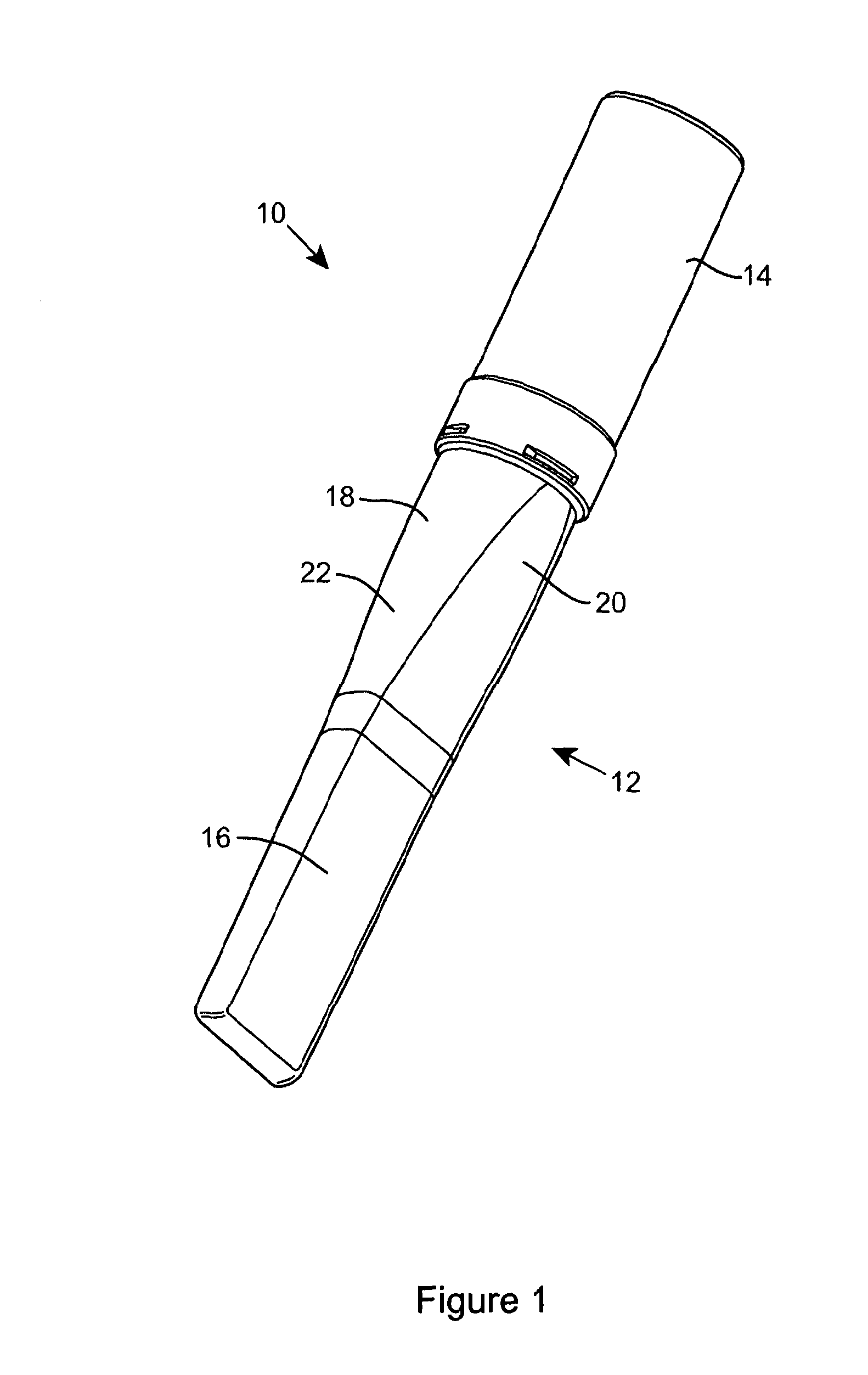
The present invention relates to a chisel case and particularly, but not exclusively, to a chisel case for storing and protecting a woodworking chisel. At present, chisel cases are generally designed to hold a number of chisels, however these cases typically do not ensure that a chisel blade is comprehensively protected from damage through contact with other tools or chisels. When in transit, chisel blades can become chipped or otherwise damaged, resulting in the chisel having to be re-sharpened prior to use. It is an object of the invention to provide a chisel case which provides a secure housing for a chisel and reduces the possibility of damage to the chisel or the blade of the chisel in storage or transport. According to the present invention there is provided a chisel case for housing a single chisel comprising first and second unitary hollow body portions, a deformable blade supporting means disposed within the first body portion and a deformable handle supporting means disposed within the second body portion, the first body portion being formed at one end as a substantially elongate rectangular box section for receiving a blade portion of a chisel. The hollow unitary first and second body portions provide a fully enclosed vessel in which a chisel can be contained therein, preventing the chisel from making potentially damaging contact with other tools. The deformable supporting means ensures the immobilisation of the chisel within the chisel case. At least one tapered transitional portion may be provided adjoining the box section, which extends to a substantially circular end and the tapered transitional portion may include two substantially planar opposing surfaces, the width of said planar surfaces increasing as the taper decreases. This reduces movement of the chisel within the case, ensures the necessary size of the case is minimised and the appearance of the case can be streamlined. The taper decreases as it approaches the elongate rectangular box section. The first body portion may be open-ended at the circular end for receiving the chisel. The circular end may be provided substantially as a ring with a continuous outwardly directed flange extending therefrom, said flange being inset from a free edge of the ring. The second body portion may be formed as a tube having a substantially circular lateral cross-section. The second body portion may be open-ended at one end for receiving a handle of the chisel. In order to ensure the second body portion remains attached to the first body portion in use, a circumferential neck may be disposed at the open end of the second body portion, said neck having a plurality of spaces provided therethrough, and the ring of the first body portion having a plurality of outwardly directed flange portions extending therefrom for engaging the spaces of the circumferential neck in a bayonet engagement. An alternative means of ensuring the first body portion remains attached to the second body portion may be provided by a circumferential neck having a radial flange being disposed at the open end of the first body portion, and the second body portion may include a circumferential recess for receiving the flange with a snap-fit. Alternatively, a circumferential neck with a screw thread may be disposed at the open end of the first body portion, and the second body portion may include a corresponding internal screw thread for engaging the threaded circumferential neck with a screw-fit. Of the above three methods of ensuring the second body portion remains attached the first body portion, the bayonet engagement is the preferred method because a user can feel the deformable supporting means deforming around and engaging a chisel as the second body portion is moved towards the first body portion. Also, the bayonet engagement limits the rotational movement required to attach the second body which prevents unnecessary abrasion of the deformable supporting means. The first body portion may also include an indicia display region disposed on the outer surface of the elongate box section, allowing identification of the chisel width able to be received by the case. The deformable blade supporting means may include a V-shaped groove for receiving a tip of the chisel blade which helps to guide the tip into a centrally disposed position within the first body portion. The effect of both deformable supporting means may also ensure a chisel contained within the case maintains a substantially spaced relationship with the inside of the case, which minimises wear of the chisel. For a better understanding of the present invention, and to show more clearly how it may be carried into effect, reference will now be made, by way of example, to the accompanying drawings, in which: Referring firstly to As best seen in Turning now to In use, as best seen in Referring now to Referring also to Referring also to When a chisel 62 is inserted blade-end first into the first body portion 52 the blade comes to rest in a supporting region of the deformable supporting means 64. This may be shaped with a V-slot to assist engagement. Then, when the cap portion 54 is moved towards and attached to the first body portion 52, the user can feel the engagement of the deformable supporting means 64 and can confirm that the chisel 62 is well supported before the cap is secured. This effect is cause by the resilience in the deformable supporting means. The chisel case is highly advantageous in storing and in particular transporting chisels. Its unitary body portions are made from durable plastics which protect a chisel blade from possible damaging contact with other tools, ensuring that a chisel contained within the case remains sharp. The deformable supporting means allow a chisel to be fully supported in a fixed position relative to the inside of the case. The chisel is maintained in a spaced relationship with the case and the deformable supporting means provides the user with confidence that the chisel is securely and safely contained within the first body portion as the second body portion is attached. It is understood that variations may be made in the foregoing without departing from the scope of the invention. For example, the elements and teachings of the various illustrative embodiments may be combined in whole or in part in some or all of the illustrative embodiments within the scope of the claims. A chisel case 50 includes a hollow unitary body portion 52 and a removable cap portion 54. The body portion 52 has a substantially cylindrical section 56 for receiving a chisel handle 70. A substantially elongate box section 58 adjoins and is integrally formed with the body portion 52 and in use receives a chisel blade 66. A chisel 62 is contained within the chisel case 50 and is supported by a deformable blade supporting means 64 disposed at the end of the elongate box section 58 and a deformable handle supporting means 68 disposed within the cap portion 54. 1-14. (canceled) 15. A chisel case for housing a single chisel comprising first and second unitary hollow body portions, co-operating engagement means provided on each body portion for locking the body portions together, a deformable blade supporting member disposed within the first body portion, the deformable blade supporting member having a V-shaped groove therein for receiving a tip of the chisel blade, and a deformable handle supporting member disposed within the second body portion, the first body portion being formed at one end as a substantially elongate rectangular box section for receiving a blade portion of the chisel. 16. A chisel case as claimed in 17. A chisel case as claimed in 18. A chisel case as claimed in 19. A chisel case as claimed in 20. A chisel case as claimed in 21. A chisel case as claimed in 22. A chisel case as claimed in 23. A chisel case as claimed in 24. A chisel case as claimed in 25. A chisel case as claimed in 26. A chisel case as claimed in BACKGROUND TO THE INVENTION
SUMMARY OF THE INVENTION
BRIEF DESCRIPTION OF THE DRAWINGS
DESCRIPTION OF PREFERRED EMBODIMENTS