LIGHT SOURCE APPARATUS
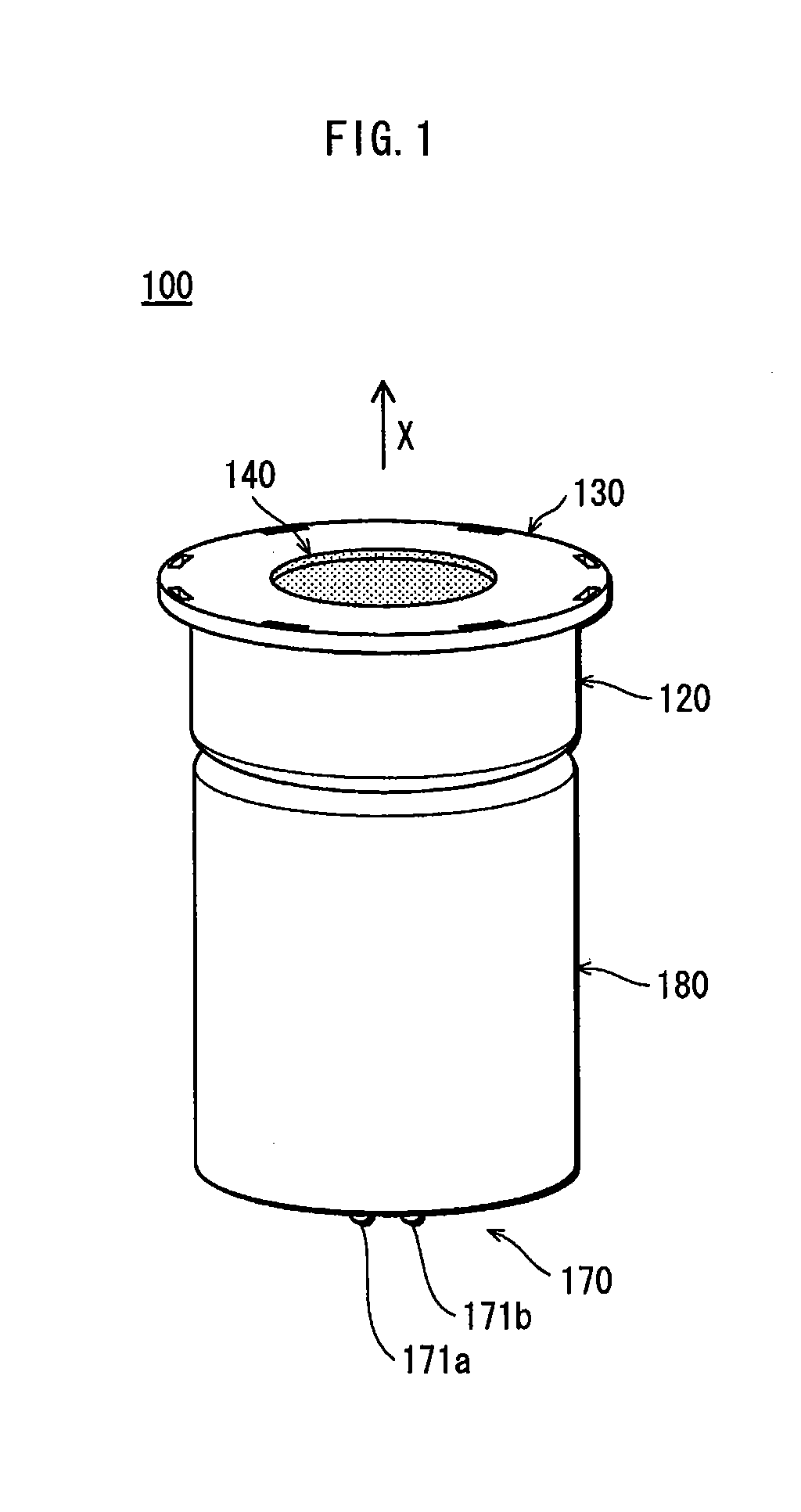
The present invention relates to a light source apparatus in which a light-emitting module such as an LED (Light-Emitting Diode) module is used as the light source. In recent years, triggered by the practical use of super luminosity LEDs, there have been attempts to use, as the substitute for halogen bulbs or incandescent bulbs, light source apparatuses having LEDs as the light source. As one of such light source apparatuses, for example, Patent Literature 1 discloses a light source apparatus 900 having a structure shown in With such a structure, it is possible to attach the front cover 905 to the body 902 by pressing and fitting the front cover 905 to the opening portion 903. With this structure, the light source apparatus can be assembled more easily than the method of attaching a metal front cover to the body by swaging, or fixing a front cover made of a metal or resin to the body by using screws or screwing them while the grooves thereof mesh with each other. When a front cover made of a metal or resin is attached to the body by bonding, there is a possibility that the bond runs out and a disfigurement is caused. However, with this structure, there is no such possibility. Thus the light source apparatus can be assembled more easily with the present structure than with the structure in which the bond is used. Japanese Patent Application Publication No. 2009-093926 However, with the above structure of the light source apparatus 900, although it is easy to attach the front cover 905, once the front cover 905 is attached, the engaging claws 904 of the front cover 905 hide behind the body 902, and it becomes difficult to remove the front cover 905 when the light source apparatus 900 is disassembled for recycling, for example. It is therefore an object of the present invention to provide a light source apparatus that can be assembled and disassembled easily. The above object is fulfilled by a light source apparatus comprising: a body having an opening portion on a front side thereof, and housing a light-emitting module; and a front cover attached to the opening portion of the body and including a light emission window for allowing light emitted from the light-emitting module to go outside, the front cover having a plurality of engaging claws and being attached to the body when the engaging claws engage with a claw receiving portion that is provided in an outer surface of the body. With the above structure of the light source apparatus of the present invention, the attachment of the front cover to the body can be performed simply by causing the engaging claws of the front cover to be in contact with the claw receiving portion provided in an outer surface of the body, and pressing the front cover onto the body. Also, after the front cover is attached to the body, the engaging members are positioned outside the body. Accordingly, the front cover can be removed easily from the body because the engaging claws can be easily removed from the claw receiving portion. On the other hand, since a plurality of engaging claws are provided, this structure prevents the front cover from being removed from the body by a slight shock. Accordingly, the light source apparatus of the present invention is both assembled and disassembled easily, and prevents the front cover from being removed by a slight shock. The following Embodiments explain examples of the light source apparatus of the present invention with reference to the attached drawings. (Structure Outline) (LED Module) The implementation substrate 111 is, for example, in the shape of an approximately octagonal plate and includes: a metal plate made of aluminum or the like on which an insulation layer made of thermally conductive resin is formed; a wiring pattern (not illustrated) formed on the insulation layer to be electrically connected with the LED; and three screw insertion holes 111 The LED 112, for example, includes: an LED chip of the InGaN type with blue emission light; and a semispherical sealing member which contains a phosphor for emitting yellow-green light and seals the LED chip therein. The LED 112 converts a part of blue light emitted from the LED chip to yellow-green by the phosphor, and emits white light that is generated as a mixture of blue light and yellow-green light. The LED 112 is implemented on the implementation substrate 111, and is electrically connected with lands 111 The connectors 113 and 114 have insulation members 113 (Body) Back to The front-side end of the cylindrical portion 122 increases in outer and inner diameters as it proceeds toward the front direction, and the part with the increased diameters constitutes the opening portion 121 of the body 120. The opening portion 121 is provided with a flange (claw receiving portion) 124 that extends outward from an outer circumferential edge of the opening portion 121. The front cover 130 is attached to the body 120 by using the flange 124. Note that the assembly structure of the front cover 130 will be described in detail later. In the bottom 123, three approximately circular screw insertion holes 125 (Front Cover) Note that the resin that constitutes the cover 130 is not limited to PBT, but may be acrylic, PC (polycarbonate) or the like. PBT is preferred as a material of the front cover 130 since it has high heat resistance, moderate elasticity, and high weather resistance. Also, the front cover 130 is not limited to white. The front cover 130 made of resin can be colored at a low cost. The front cover 130 is provided with eight engaging claws 134 The engaging claws 134 On the other hand, for example, when an engaging claw is formed like a ring to be continuous along the outer circumferential edge of the front cover, if one portion of the continuous engaging claw is removed from the flange 124, the entire engaging claw connected with the portion might be removed from the flange 124. Thus with this structure, the cover 130 may be easily removed from the body 120. Also, when the front cover 130 is attached or detached, the stress applied to the engaging claws is apt to be concentrated on one portion of the engaging claws. Thus with this structure, attachment/detachment requires a large force, and the engaging claws are easy to break. Note that the number of the engaging claws 134 The main body 132 of the front cover 130 is provided with holes 135 Also, in the present embodiment, tips 139 of the engaging claws 134 (Lens) Back to The lens 140 is an optical member for collecting the light from the LED module 110. The light emitted from the LED 112 is acquired by the lens 140, collected by the lens 140, and released to outside of the body 120. When the lamp is used as a spotlight, it is preferable that an LED whose beam angle is at most 140° is used as the LED 112 to facilitate the collection of light. (Lighting Unit) The lighting unit 150, for example, may include a lighting circuit provided with: a rectifier circuit that rectifies an AC power supplied from a commercial power source to a DC power; and a voltage adjustment circuit that adjusts a voltage value of the DC power rectified by the rectifier circuit. The lighting unit 150 causes the LED module 110 to emit light, by using the commercial power source. As shown in (Case) The case 160, for example, is in the shape of a cylinder with a bottom, wherein the lower end is closed and the upper end is opened, and is made of an insulation material such as resin or ceramic. The case 160 houses the lighting unit 150 inside. On an inner circumferential surface 161 of the case 160, three protrusions 162 (Base) The base 170 is composed of base pins conforming to “GU5.3” defined in the JIS C 7709 standard so as to be adaptable to the socket for halogen bulb. The base 170 illustrated in (Heat Sink) “The Structure as Such” The heat sink 180 includes a cylindrical part 181 and an end wall 182, and is made of a material that has excellent heat radiation, such as a metal or ceramic. The end wall 182 is in the shape of a circular plate and closes the upper end of the cylindrical part 181. Due to the simple shape as such, the heat sink 180 can be manufactured by the drawing process, and can be made thin. This contributes to reduction in weight of the light source apparatus 100. Note that the heat sink 180 may be manufactured by a method, such as diecasting, other than the drawing process. The cylindrical part 181 fits to the outside of the case 160, and for example, covers, in its entirety, an outer circumferential surface 165 of the case 160. The structure as such covering the outer circumferential surface in its entirety increases the surface area of the cylindrical part 181, improves the heat radiation, and improves the outer appearance of the light source apparatus 100. The above structure having the heat sink 180 is in particular effective in a light source apparatus for spotlight, which tends to have a problem of increase in temperature due to LED because a small, super-luminosity LED is apt to be used. The inner diameter of the heat sink 180 is larger than the outer diameter of the case 160 such that a gap 101 (see The end wall 182 is provided between the body 120 and the case 160, closing the opening of the case 160. In the end wall 182, three screw insertion holes 184 Since, in the light source apparatus 100, the heat sink 180 is provided as a separate body from the body 120 and the case 160, the heat sink 180 can be changed in shape and size appropriately based on the level of wattage, while allowing the body 120 and the case 160 to be used in common in a plurality of types of light source apparatuses that have different levels of wattage. This reduces the cost because some structural elements can be used in common, and also facilitates development of various types of light source apparatuses. (Assembly Structure) The light source apparatus 100 in Embodiment 1 described above is assembled as follows. First, as shown in Next, the implementation substrate 111 of the LED module 110 is mounted on the bottom 123 of the body 120, then the connectors 113 and 114 are passed through the connector insertion holes 185 Next, fixing by screws is performed. The screws 190 Note that, to the light source apparatus 100, the following assembly structure may be applied. A plurality of types of parts that are different in shape and size but are common in position of the screw insertion holes and connector insertion holes are prepared with respect to each of the parts constituting the light source apparatus 100, and based on the wattage and specifications of the lighting equipment for the target apparatus, parts of the appropriate type are selected from the prepared parts, and combined appropriately. The outer diameter of an outer circumferential part 142 of the lens 140 is larger than the diameter of the light emission window 131. Accordingly, when the front cover 130 is attached to the body 120, the lens 140 is housed inside the light emission window 131, and the outer circumferential part 142 of the lens 140 is covered by an inner circumferential part 137 of the main body 132 of the front cover 130. This structure prevents the lens 140 from dropping off from the light emission window 131. In this state, the lens 140 is sandwiched by the front cover 130 and the LED module 110. This restricts the movement of the lens 140 in the front and back direction, and maintains the state where a part of the LED 112 is fitted in the concave 141. This prevents the lens 140 from being shifted relative to the LED 112 in position. On the other hand, a back-side outer circumferential portion 128 of the flange 124 is angled sufficiently to make it difficult for the engaging claws 134 Back-side portions 138 of the engaging claws 134 On the other hand, front-side portions 139 of the engaging claws 134 It is preferable that, in the front cover 130, a width W8 of the circumferential wall 133 in the cylindrical axis direction and a width W9 of a projection projecting from the body 120 in the direction perpendicular to the cylindrical axis direction both conform to the JIS C 7527 standard so that the light source apparatus 100 can be attached to the lighting fitting for the halogen bulb. In this structure, as indicated by arrows in As shown in The light source apparatus 200 includes the LED module 110, the body 120, the front cover 130, the lens 140, the lighting unit 150 (not illustrated), the case 160 (not illustrated), the base 170 (not illustrated), the heat sink 180, and a ring 201. Attachment of the front cover 130 is performed as follows. As shown in The ring 201, which is made of rubber or the like, is arranged between the body 120 and the front cover 130. In the state before the ring 201 is attached to the front cover 130, a height level L1 of an upper end of the ring 201 is higher than a height level L2 of an upper surface of the outer circumferential part 142 of the lens 140; and in the state after the ring 201 is attached to the front cover 130, the height level L1 is lower than the height level L2. That is to say, the ring 201 becomes flat when it is pressed by the back face of the front cover 130. In this way, by arranging the ring 201 between the body 120 and the front cover 130, the lens 140 is fixed to a predetermined position with ease, and the positional shift of the lens 140 is prevented with more certainty. It is preferable that the thickness of the main body 132 of the front cover 130 is in a range from 0.5 mm to 2.0 mm so that the front cover 130 has elasticity to a suitable extent for the lens 140 to be pressed against the body 120. If the main body 132 is thinner than 0.5 mm, the front cover 130 may not have a sufficient mechanical strength, and if the main body 132 is thicker than 2.0 mm, the front cover 130 may not have a sufficient elasticity. With this structure where the ring 201 is arranged between the body 120 and the front cover 130, the inside of the body 120 is approximately in a hermetically closed state since it does not communicate with the outside. Accordingly, the LED module 110, which is housed in the body 120, is hermetically sealed. This makes it difficult for the LED module 110 to have a failure by humidity even if the light source apparatus 200 is used in a highly humid environment. The light source apparatus 300 in Embodiment 3 includes the LED module 110 (not illustrated), a body 320, a front cover 330, the lens 140, the lighting unit 150 (not illustrated), the case 160 (not illustrated), the base 170, and the heat sink 180. The body 320, for example, is formed in the shape of a cylinder with a bottom, from a material that has excellent heat radiation, such as a metal or ceramic (including glass), and has an opening portion 321 at an end on the front side. The body 320 includes a cylindrical portion 322 and a bottom (not illustrated) which is in the shape of a circular plate and closes the lower end of the cylindrical portion 322. In the vicinity of the front end of the outer circumferential face of the cylindrical portion 322, four engaging holes (claw receiving portions) 324 The front cover 330 is made of, for example, white PC, and includes: a main body 332 that is in the shape of a ring-like plate and has an approximately circular light emission window 331 at approximately the center thereof; and a circumferential wall 333 that is in the shape of a short cylinder extending backward from the outer circumferential edge of the main body 332. The back-side end of the circumferential wall 333 has tongues 335 The front cover 330 is attached to the opening portion 321 of the body 320 by causing the engaging claws 334 The LED unit 410 is the light source of the light source apparatus 400 and has approximately the same structure as the LED module 110 in Embodiment 1 except, for example, that it includes an implementation substrate 411 and an LED (light-emitting element) 412, and that the implementation substrate 411 has the shape of an approximately circular plate. The body 420, for example, is made of a material that has excellent heat radiation, such as a metal or ceramic (including glass), has an approximately conical shape, and includes a cylindrical portion 422 and a bottom 423 which is in the shape of a circular plate and closes the lower end of the cylindrical portion 422. The LED module 410 is attached onto the bottom 423. The front-side end of the cylindrical portion 422 increases in outer and inner diameters as it proceeds toward the front direction, and the part with the increased diameters constitutes the opening portion 421 of the body 420. A flange (claw receiving portion) 424 is provided in the opening portion 421 to extend outwardly from an outer circumferential edge of the opening portion 421, and the front cover 130 is attached by using the flange 424. The base unit 470 is a base defined in the JIS C 7709 standard that can be adapted to the socket for halogen bulb, and includes a pair of base pins 471 As described above, the light source apparatus 400 is formed to have a similar outer appearance to the halogen bulb, and thus, as a substitute for the halogen bulb, can be attached to more lighting fittings. Up to now, specific examples of the light source apparatus of the present invention have been explained in the embodiments. However, the light source apparatus of the present invention is not limited to these embodiments. For example, the following modifications are considered. (Light-Emitting Module) The light-emitting element for the light-emitting module is not limited to LED, but may be a semiconductor laser diode or an electroluminescence element. Also, the color of the light emitted by the light-emitting element is not limited to white, but may be any color of light. (Body) The claw receiving portion of the body is not limited to the flanges 124 and 424 of Embodiments 1, 2 and 4 and the engaging holes 324 Also, the body may be made of a light transmissive material. In that case, the light emitted from the LED module passes through the body and leaks from the side of the light source apparatus to outside. This broadens the lighting region of the light source apparatus. Note that the light transmissive material may be light transmissive ceramic such as glass. The above structure is especially effective in the case where the light source apparatus is not used as a spotlight. In this case, it is further preferable that the body is made of a material that has the light diffusion function. Furthermore, it is further preferable that the body is paired with a front cover having functions to transmit and diffuse the light. (Front Cover) The material of the front cover is not limited to a non-light-transmissive resin, but may be a light transmissive resin. The front cover made of a light transmissive resin enables the light to be emitted from the whole front face of the light source apparatus. Also, the light that leaks from the lens reflection surface is extracted from the front cover to outside of the body, thus the amount of emitted light increases. Furthermore, the front cover may be made of a resin having functions to transmit and diffuse the light. With this structure, the light emitted from the LED module is diffused at the front cover, providing a light distribution pattern that is close to that of the incandescent lamp. Furthermore, the light emission window of the cover may not be opened, but may be closed by a light transmissive resin or the like. (Lens) The optical member may be a Fresnel lens or a reflection mirror. When a lens is used as the optical member, it is preferable that a reflection layer for reflecting the light is provided on the surface of the lens. If the surface of the lens is provided with the reflection layer so that the lens is surrounded by a mirror facing inward, the amount of emitted light increases. Note that the optical member is not necessarily required. The light source apparatus may have a structure that is not provided with an optical member. In that case, for example, in Embodiment 1, the main body 132 of the front cover 130 may not be provided with the light emission window 131, and the opening portion 121 of the body 120 may be entirely covered by the main body 132. Furthermore, the optical member 140 and the front cover 130 may be formed as one unit. In other words, a part of the front cover may be formed to function as the optical member. (Others) The light source apparatus of the present invention may be any combination of structural elements of Embodiments 1 through 4. The light source apparatus of the present invention can be extensively used for lighting in general. 100, 200, 300, 400 light source apparatus 110, 410 light-emitting module 120, 320, 420 body 121, 321, 421 opening portion 124, 424 flange (claw receiving portion) 127 front-side outer circumferential portion 130, 330, 430 front cover 131, 331, 431 light emission window 134 138 back-side portion of engaging claw 140 optical member A light source apparatus that can be assembled and disassembled easily. A light source apparatus 100 includes: a body 120 housing a light-emitting module 110; and a front cover 130 attached to an opening portion 121 of the body 120 and including a light emission window 131 for allowing light emitted from the light-emitting module 110 to go outside. The opening portion 121 is provided on a front side of the body 120. The front cover 130 includes a plurality of engaging claws 134a through 134f and is attached to the body 120 when the engaging claws 134a through 134f engage with a claw receiving portion 124 provided in an outer surface of the body 120. 1. A light source apparatus comprising:
a body having an opening portion on a front side thereof, and housing a light-emitting module; and a front cover attached to the opening portion of the body and including a light emission window for allowing light emitted from the light-emitting module to go outside, the front cover having a plurality of engaging claws and being attached to the body when the engaging claws engage with a claw receiving portion that is provided in an outer surface of the body, and the engaging claws being provided at intervals along an outer circumferential edge of the front cover. 2. The light source apparatus of the claw receiving portion is a flange extending outward from a front-side outer circumferential edge of the body, the engaging claws having gone around behind the flange to engage with the flange. 3. The light source apparatus of a front side of an outer circumferential edge of the flange is in a round or tapered shape. 4. The light source apparatus of a back side of each engaging claw is in a round or tapered shape. 5. (canceled) 6. The light source apparatus of the light emission window is provided with an optical member for collecting light from the light-emitting module. 7. The light source apparatus of a back side of each engaging claw is in a round or tapered shape. 8. The light source apparatus of a back side of each engaging claw is in a round or tapered shape. 9. The light source apparatus of the light emission window is provided with an optical member for collecting light from the light-emitting module. 10. The light source apparatus of the light emission window is provided with an optical member for collecting light from the light-emitting module. 11. The light source apparatus of the light emission window is provided with an optical member for collecting light from the light-emitting module. TECHNICAL FIELD
BACKGROUND ART
CITATION LIST
Patent Literature
[Patent Literature 1]
SUMMARY OF INVENTION
Technical Problem
Solution to Problem
Advantageous Effects of Invention
BRIEF DESCRIPTION OF DRAWINGS
DESCRIPTION OF EMBODIMENTS
Embodiment 1
Embodiment 2
Embodiment 3
Embodiment 4
[Modifications]
INDUSTRIAL APPLICABILITY
REFERENCE SIGNS LIST