System And Method For Objective Chromatic Perimetry Analysis Using Pupillometer
The present invention relates to a system, device and a method for visual field testing and in particular, to such a system and method in which provides objective chromatic perimetry test or color vision test using a pupillometer. A visual field test also known as perimetry, is a method of measuring an individual's entire scope of vision that is, the central and peripheral vision. Such visual field tests attempt to map the visual field of each eye individually. Visual field testing is most frequently used to detect any signs of glaucoma caused damage to the optic nerve. In addition it is useful for detection of central or peripheral retinal disease, eyelid conditions such as ptosis or drooping, optic nerve disease, and diseases affecting the visual pathways within the brain and associated with the Central Nervous System (“CNS”). The present prevailing method for visual field testing is performed as follows: one eye of the patient is covered and the chin is placed on a concave chin rest. The patient must look straight ahead at all times in order to avoid testing the central vision rather than the periphery. Next, light flashes of various intensities and locations are projected on the tested eye. Whenever the patient notices a flash he has to push a button. After all the relevant looking angles are covered a computer program analyzes the patient's responses and assesses the visual field map of the tested eye. The principal stumbling block of the above procedure is its subjectivity, requiring the patient to understand the testing instructions, fully cooperate, and complete the entire test in order to provide useful information. However, the patient cooperation may strongly depend on his level of fatigue, wakefulness and attentiveness. This problem is especially severe in case of ill or elderly patients, younger children or patients with mental disabilities and developmental delay. Consequently, the test results obtained by the current method may not be accurate and may lead to false medical diagnosis. Moreover, the results may not be repeatable, which does not allow for reliable and effective tracking of the patient's medical condition. Additional tests to assess the state of the eye is the Pupillary Light to Reflex (“PLR”) to provide clinical signs of the condition associated with the CNS. The PLR test the pupil response, namely constriction, by testing the pupil's stimulus response in each eye where a healthy eye is indicative of symmetric constriction of both pupils. A quantitative measurement of a PLR may be obtained using a pupillometer. Pupil perimetry utilizes a pupillometer together with a stimulus arrangement similar to that of a perimeter to measures the latency and amplitude of the constriction of the pupil in response to a stimuli, usually in the form of a spot (“small-area”) flashes of light that is directed to different locations on the retina. The pupillary response to spatially-localized luminance increments has been used as an indicator of glaucomatous retinal damage, but the small-area stimuli used in pupil perimetry may target small retinal areas that only weakly stimulate a PLR, and may fail to stimulate a PLR if the small retinal area that is being stimulated by light has been damaged by glaucoma. Standard pupil perimetry testing produce large variations in pupil response amplitude among patients and the changes in sensitivity of the pupil response with the retinal location of the small-area light stimulus have also limited the usefulness of such measurements. Pupillometer based objective visual tests have been recited in some references, based on an achromatic beam stimulus which is applied at various angles, for example U.S. Pat. No. 5,610,673 to Rafal et al, U.S. Pat. No. 7,524,064 to Wyatt, U.S. Pat. No. 7,258,444 to Gorin. However, these methods fail to achieve neither accurate nor repeatable visual field mapping due to its susceptibility to time variations in the human ocular system and to differences in the behavior of the ocular system of different patients. There is an unmet need for, and it would be highly useful to have, a system and a method for objective chromatic perimetry analysis using pupillometer that is adept at providing an indication of the state of health of the eye and in particular identifying damage to the eye. The present invention overcomes the deficiencies of the background by providing a system and method that provides an objective test and analysis that is able to quantify an individual's state of health of the eye. The system and method overcome the deficiencies of the art by providing individual specific indication of problem areas of the eye in obtaining measurements that are relative to an individual's field of vision at specific visual field testing points, rather than full field test provided by the prior art. Moreover the objective test of optional embodiments of the present invention provides for a quick test that does not require patient specific interaction or input, that is subjective and often unreliable or misleading. Rather the test of the present invention most preferably measures a subject's PLR without a subject's input ensuring the objective nature of the test, hence more reliable and repetitive. An optional embodiment of the present invention provides a system and method for testing an individual's response to at least two or more stimuli that are individually associated with the anatomical tissue, cells, ganglion, or the like anatomical structures comprising the eye, for example including but not limited to ganglion, most preferably the rods and cones, and elucidating a ratio reflective of the relative response of the stimuli utilized. For example the ratio utilized may comprise at least two response measurements associated with the group comprising of rods, cones, ganglion in any combination thereof, therein providing for a ratio selected from the group consisting of rods to cones; rods to ganglion, cones to ganglion, or the like. An optional embodiment of the present invention provides a system and method for testing an individual's response to at least three or more stimuli that are individually associated with the anatomical tissue, cells, ganglion, or the like anatomical structures comprising the eye, for example including but not limited to ganglion, rods and cones, and optionally elucidating at least one or more ratio reflective of the relative response of the stimuli utilized; more preferably elucidating at least two ratios reflective of the relative response of the stimuli utilized. For example, at least two ratios utilized may for example be any combination of the ratio selected from the group comprising rods to ganglion, cones to ganglion, rods to cone, ganglion to rods, ganglion to cones, or the like. Optionally the evaluation of the eye may be provided by a utilizing a ratio comprising a common denominator for example, a ratio of rods to ganglion may be compared and evaluated with respect to the ratio of cones to ganglion. A preferred embodiment of the present invention introduces at least two or more stimuli comprising at least one cone specific stimulus and at least one rod specific stimulus, to a plurality of location herein referred to as the visual field points (‘VFP’) of at least one eye, and measuring the PLR response, namely pupil constriction, via a pupillometer; and comparing the PLR response, at a given VFP, of the respective stimulus to obtain a ratio indicative an individual's state of health of the eye. For example, stimulus that is geared toward the rod and stimulus is provided in the form of chromatic light flashes comprising a short wavelength most preferably a narrow beam within the blue spectrum range, for example including but not limited to wavelength of about 450 nm, 455 nm, 460 nm, 465 nm, 470 nm, 475 nm, 480 nm, 485 nm, 490 nm or the like, most preferably the stimuli utilized is about 485 nm. Optionally the cone specific stimulus is provided in the form of chromatic light flashes comprising a long wavelength most preferably narrow beam within the red spectrum range, for example including but not limited to wavelength of about 630 nm, 635 nm, 640 nm, 645 nm, 650 nm, 655 nm, 660 nm, 665 nm, 670 nm, 675 nm, 680 nm, 685 nm, 690 nm, 695 nm, 700 nm any combination thereof or the like. Optionally and preferably the ratio obtained according to optional embodiment of the present invention is a ratio of cone specific stimulus response to a rod specific stimulus response. Optionally the ratio utilized may be region specific about the different visual field points tested. For example, the central field points of the VFP may optionally utilize a ratio determined by rod specific stimulus response to cone specific stimulus response, while the peripheral field points may utilize a ratio of cone specific stimulus response to a rod specific stimulus response, as an indication of eyes state of health in the particular region and/or visual field point. Optionally the ratio provided by the system and method of the present invention provides for individual specific measurements, reduce variability between the tested population, an indicator of an individual's internal state of balance associated with the sympathetic and parasympathetic state. Optionally utilization of the ratio accounts for and reduces variability due to light scattering and supranuclear inhibition. Optionally the ratio according to the present invention may account for the variability among the population pupil size, therein providing a standardized measurement relative to an individual rather than a population. Optionally and preferably the ratio is adept at assessing and providing an indication of the extent of an individual's visual field rim. The present invention resolves the above background art limitations by providing, in at least some embodiments, a reliable and objective visual field testing, that is reliable and repeatable. An optional embodiment of the present invention provides a decision support system for diagnosing eye and/or retinal damage by assessing a subject's PLR in response to at least two or more chromatic stimuli to define a ratio indicative of the underlying state of health of the tested eye. Optionally the at least two stimuli is composed of a first stimulus comprising a short wavelength chromatic stimulus and a second stimulus comprising a long wavelength chromatic stimulus, and wherein the ratio is the determined by evaluating the long wavelength PLR response with respect to the short wavelength PLR response of the tested eye. Optionally the first stimulus is within the blue range from about 450 nm to about 490 nm, optionally and preferably about 475 nm, more preferably 480 nm and most preferably 485 nm. Optionally the second stimulus is within the red range from about 635 nm to about 700 nm, optionally and preferably about 650 nm. An optional embodiment of the present invention provides a system for objective chromatic perimetry test comprising a pupillometer, a process and a camera that most preferably does not require subject input: a. the pupillometer comprising: i. a testing compartment provided in the form of a hemispheric bowl, wherein an inner surface of the bowl comprises a plurality of openings forming form a plurality of visual field testing points; and ii. wherein the hemispheric bowl may be associated with a plurality of chromatic beam emitters arranged about the visual field such that they are disposed over the plurality of visual field testing points; and wherein the chromatic emitters provide for generating a chromatic stimuli about the visual field points; and wherein iii. the stimuli comprises at least two different stimulus selected from the visual spectrum spanning from about 390 nm to about 750 nm wherein the different stimulus are individually characterized by their individual stimulus parameters including wavelength, duration, delay, and intensity; and iv. wherein the outer perimeter of the inner surface of the testing compartment further comprises a light adaptation emitter wherein the adaptation emitter comprising at least one or more chromatic beam emitters; and v. The inner surface further comprising a fixation point opposite a subject's line of sight; and vi. The bowl further comprising at least one or more opening for at least one or more camera provided for recording the pupil contraction in response to the stimuli; and b. The processor provided for controlling the chromatic beam emitters, the stimulus parameters and the visual field points; and wherein the processor processes data associated with and generated by the stimulus and camera. Optionally and preferably the device according to the present invention may be adapted to provide for color vision testing. Optionally the stimuli may include a first stimulus characterized in that it may be a short wavelength chromatic beam and a second stimulus characterized in that it may be a long wavelength chromatic beam. Optionally the stimuli comprises up to three individual stimulus. Optionally the first stimulus may be provided in the form of a chromatic beam in the blue wavelength range centered at about 480 nm or about 485 nm. Optionally the chromatic beam stimulus may be selected from about 450 nm to about 495 nm comprises a blue wavelength beam selected from about the group consisting of about 450 nm, 455 nm, 460 nm, 465 nm, 470 nm, 475 nm, 480 nm, 485 nm, 490 nm, 495 nm, 500 nm or any combination thereof. Optionally the second stimulus may be a chromatic beam in the red wavelength range centered at about 640 nm or about 620 nm. Optionally the second stimulus chromatic beam may be selected from about 590 nm to about 750 nm and comprising red wavelength selected from the group for example including but not limited to about 610 nm, 615 nm, 620 nm, 625 nm, 630 nm, 635 nm, 640 nm, 645 nm, 650 nm, 655 nm, 660 nm, or any combination thereof. Optionally the first stimulus and the second stimulus are adapted to individually stimulate a specific anatomical structure of the eye. Optionally the first stimulus may be adapted to stimulate rods and ganglion while the second stimulus may be adapted to stimulate cones. An optionally the stimulus may be characterized in that it may be specific an anatomy of the eye; and wherein the system of the present invention comprises at least two stimuli that may be generated to simulate at least two anatomical structures of the eye. Optionally a light adaptation emitter comprises three chromatic beam emitters adapted to produce a visible color about the inner surface of the bowl of the test compartment. Optionally the hemispheric bowl may be provided in the form of a ganzfeld dome or a Goldmann, or static perimeters. Optionally the plurality of chromatic beam emitters or the plurality of openings are further provided with a controllable shutter for controlling the size and shape of the generated stimulus. Optionally and preferably the shutter size may be adapted to provide a stimulus having a substantially circular formation with a diameter from about 0.8 cm to about 2 cm. Optionally and preferably shutters may be controllable with the processors. Optionally the plurality of chromatic beam emitters are provided in the form of a Light Emitting Diode (‘LED’). Optionally the LED provides a specific chromatic beam characterized in that it may be specific to an anatomy of the eye. Optionally the LED may provide a plurality of optional specific chromatic beams characterized in that each beam may be individually specific to an anatomy of the eye. Optionally the chromatic beam emitters or the openings about the inner surface of the test compartment are arranged to provide from about 13 to about 256 visual filed testing points about the vertical and horizontal planes of the hemispheric bowl. Optionally each of the visual field point comprises at least one chromatic beam emitters in the form of a LED that may provide a plurality of optional specific chromatic beams. Optionally the device according to the present invention may be configured such that each of the visual field points may comprise at least two chromatic beam emitters in the form of a LED characterized in that each LED provides a specific chromatic beam. Optionally the device according to the present invention may be configured such that each of the visual field point comprises at least three chromatic beam emitters that may optionally be provided in the form of a LED. Optionally the chromatic beams may be further characterized in that each beam may be individually specific to an anatomic structure of the eye, for example including but not limited to the rods and cones, ganglion. Optionally the fixation point may be disposed at about the pole of the hemispheric bowl and may comprise up to four fixation points about the center. Optionally the system according to the present invention may comprise at least one and up to four cameras, for objectively recording the PLR of subject. Optionally the system may comprise at least one, or at least two, or at least three or at least four cameras. Optionally the PLR may be recorded for each eye utilizing at least two cameras. Optionally the shutter may for example be provided in the form of a static shutter or a dynamic shutter, or a combination thereof or the like. Optionally the stimulus duration or delay may be controllably set to be any single value or range of values selected from about 100 ms to about 4000 ms. Optionally the stimulus intensity used with the system and method according got the present invention may be controllably set to be any single value or range of values from about from 3.98×10⁻⁸cd/m2up to about 3.98×10²cd/m2. An optional embodiment of the present invention provides for a method for determining the state of health of an eye with a pupillometer providing an objective chromatic perimetry analysis test, where most preferably a subject's input is not required and therefore the test is preformed and results are analyzed independently of subject's input. Most preferably the a measurement of the PLR in response to chromatic beam stimuli is presented at a plurality of visual field testing points, and defining a ratio of the measured PLR at each of the plurality of visual field testing points in response to a first chromatic beam stimulus relative to a response to a second chromatic beam stimulus, wherein the first and second stimulus are characterized by parameters for example including but not limited to wavelength, duration, delay, and intensity; and wherein the stimuli wavelength are selected from the visual spectrum spanning from about 390 nm to about 750 nm. Optionally the first chromatic beam stimulus may be a short wavelength beam and the second chromatic beam stimulus may be a long wavelength beam. Optionally the first chromatic beam may be within the blue wavelength spectrum range centered at about 480 nm or about 485 nm; and the second chromatic beam may be a chromatic beam within the red wavelength spectrum range centered at about 640 nm or about 620 nm. Optionally the ratio of the PLR measured with the long wavelength response relative to the PLR measured with the short wavelength response. Optionally the first and second chromatic beam stimuli are specific to different anatomical structure within the eye, for example including but not limited to rods, cones and ganglion. Optionally the first stimuli may be directed at the rods; and the second stimuli may be directed at the cones. Optionally the first stimulus may be provided for a duration of about 1 s (one second), with an intensity of about 3.98×10⁻⁸cd/m2, with an inter-stimulus pause of about 891 ms (milliseconds); and the second stimulus may be provided for a duration of about 1 s (one second), with an intensity of about 3.98×10⁻⁸cd/m2, with an inter-stimulus pause of about 1023 ms (milliseconds). Optionally the first and second stimulus may be presented to a subject at least once and up to three time for each visual field testing point. Most preferably the ratio may be mapped to a visual field map. Optionally and preferably the ratio or map thereof may be indicative of the state of health of anatomical structures correlated with individual visual field points. Optionally the ratio that may be indicative of underlying normal and/or healthy anatomical structures are provided by the following field point coordinates and expected ratio (0°, nasal, 0.50); (10°, nasal, 0.41); (10°, temporal, 0.45); (10°, up, 0.48); (10°, down, 0.43); (20°, nasal, 0.40); (20°, temporal, 0.33); (20°, up, 0.38); (20°, down, 0.39); (30°, nasal, 0.50); (30°, temporal, 0.44); (30°, up, 0.5); (30°, down, 0.40). Optionally the ratios may be indicative of the state of health of an eye associated with glaucoma, and retinitis pigmentosa (RP). Optionally the ratios may be indicative of the state of health of an eye associated with color blindness. Optionally and preferably the test according to the present invention may be performed with background luminance providing for light adaptation. Optionally and preferably background luminance and light adaptation may be controllable, preferably provided to facilitate testing of an anatomical structure of the eye. Optionally the background luminance may be any one value or a range of values selected from about 1 cd/m2to about 20 cd/m2. Optionally background luminance may be about 2.7 cd/m2or about 17.1 cd/m2(about 5 foot-lambert). Optionally the onset of light adaptation may be controlled and therefore provided at a plurality of optional portions of the test or at different controllable periods of the test, for example including but not limited to between stimulus presentations, between visual field testing points, between visual field rings, or any combination thereof or the like. An optional embodiment of the present invention provides device in the form of a pupillometer for performing an objective chromatic perimetry test, that most preferably does not require a subject's input, the device comprising a pupillometer testing compartment and at least one or more camera, the pupillometer testing compartment comprising: a. the testing compartment provided in the form of a hemispheric bowl, wherein an inner surface of the bowl comprises a plurality of openings forming form a plurality of visual field testing points; and b. wherein the hemispheric bowl may be associated with a plurality of chromatic beam emitters arranged about the visual field such that they are disposed over the plurality of visual field testing points; and wherein the chromatic emitters provide for generating a chromatic stimuli about the visual field points; and wherein c. the stimuli comprises at least two different stimulus selected from the visual spectrum spanning from about 390 nm to about 750 nm wherein the different stimulus are individually characterized by their individual stimulus parameters including wavelength, duration, and intensity; and d. wherein the outer perimeter of the inner surface of the testing compartment further comprises a light adaptation emitter wherein the adaptation emitter comprising at least one or more chromatic beam emitters; and e. The inner surface further comprising a fixation point opposite a subject's line of sight; and f. The bowl further comprising at least one or more opening for at least one or more camera provided for recording the pupil contraction in response to the stimuli. An optional embodiment of the present invention provides for determining the a ratio of the PLR response at individual visual field testing points based on a response to at least two or more, or three or more, or four or more chromatic beam stimuli presented to a tested eye. Optionally a different ratio may be determined based on how the eye was stimulated for example each eye individually, both eyes in turn, or both eyes simultaneously. Unless otherwise defined the various embodiment of the present invention may be provided to an end user in a plurality of formats, platforms, and may be outputted to at least one of a computer readable memory, a computer display device, a printout, a computer on a network or a user. Unless otherwise defined, all technical and scientific terms used herein have the same meaning as commonly understood by one of ordinary skill in the art to which this invention belongs. The materials, methods, and examples provided herein are illustrative only and not intended to be limiting. Implementation of the method and system of the present invention involves performing or completing certain selected tasks or steps manually, automatically, or a combination thereof. Moreover, according to actual instrumentation and equipment of preferred embodiments of the method and system of the present invention, several selected steps could be implemented by hardware or by software on any operating system of any firmware or a combination thereof. For example, as hardware, selected steps of the invention could be implemented as a chip or a circuit. As software, selected steps of the invention could be implemented as a plurality of software instructions being executed by a computer using any suitable operating system. In any case, selected steps of the method and system of the invention could be described as being performed by a data processor, such as a computing platform for executing a plurality of instructions. Although the present invention is described with regard to a “computer” on a “computer network”, it should be noted that optionally any device featuring a data processor and/or the ability to execute one or more instructions may be described as a computer, including but not limited to a PC (personal computer), a server, a minicomputer, a cellular telephone, a smart phone, a PDA (personal data assistant), a pager. Any two or more of such devices in communication with each other, and/or any computer in communication with any other computer, may optionally comprise a “computer network”. The invention is herein described, by way of example only, with reference to the accompanying drawings. With specific reference now to the drawings in detail, it is stressed that the particulars shown are by way of example and for purposes of illustrative discussion of the preferred embodiments of the present invention only, and are presented in order to provide what is believed to be the most useful and readily understood description of the principles and conceptual aspects of the invention. In this regard, no attempt is made to show structural details of the invention in more detail than is necessary for a fundamental understanding of the invention, the description taken with the drawings making apparent to those skilled in the art how the several forms of the invention may be embodied in practice. In the drawings: The principles and operation of the present invention may be better understood with reference to the drawings and the accompanying description. The following reference labels listed below are used throughout the drawings to refer to objects having similar function, meaning, role, or objective.
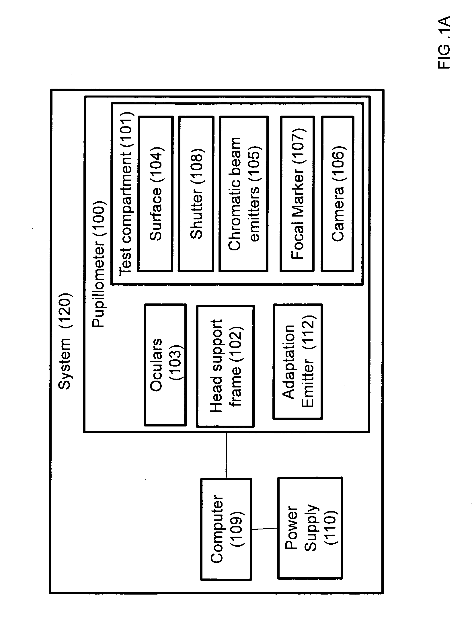
Referring now to the drawings, Test compartment 101 preferably comprises and incorporates and is integrated with inner surface 104, where surface 104 is associated with at least one or more preferably a plurality of chromatic beam emitters 105 that preferably provide for generating and presenting the stimulus for a which a response is measured. Focal fixation point marker 107 provides a subject with a fixation point during the test, optionally and preferably fixation point comprises 4 beams of red light arranged about a central point on surface 104, most preferably the pole of surface 104. Camera 106, for example in the form of a CCD camera or a the like digital camera, may be provided within test compartment and is preferably directed toward the tested eye so as to allow for visualizing and recording the pupil during testing therein providing for recording the PLR of the tested eye. Most preferably at least one camera 106, may be disposed within test compartment 101, optionally at least one and up to four cameras may be provided and arranged within test compartment 101 to better identify the PLR of the tested eye. Optionally two cameras' may be utilized to record a single tested eye. Optionally two cameras may be utilized to record a subject PLR when both eyes are tested simultaneously. Optionally up to four cameras may be utilized to record a subject PLR when both eyes are tested simultaneously, wherein at least one camera and more preferably at least two cameras are provided to record the PLR of each tested eye. Most preferably camera 106 transmits and records the subject's eye during testing sending data to computer 109 or the like processor for analysis, for example including but not limited to a server, PDA, smart phone or the like device comprising a processor. Most preferably data obtained by at least one or more camera 106 is processed with computer 109 via dedicated software. Optionally camera 106 may be attached, coupled or otherwise associated with surface 104. Most preferably camera 106 continuously captures images of at least one of the tested eye, or of both eyes for example when the consensual reflex is tested. Optionally camera 106 may be substantially simultaneously controlled with emitters 105 by computer 109. Most preferably camera 106 continuously transfers images of the pupil to computer 109 at a rate of about 50 shots-per-second, or 40 shots per second or the like. Optionally the pupillary images may be provided and/or transferred in various forms for example including but not limited to stills, common digital video format or the like as is known in the art. Optionally camera 106 may communicate and/or transfer data to computer 109 through a plurality of optional communication technology and/or protocols for example including but not limited to wired, wireless, cellular, optical or acoustic communication protocols for example including but not limited to infrared, Bluetooth, wifi or the like. Optionally computer 109 may further provide for a decision support tools associated with the sate of health of the eye. Optionally a decision support tool may provide physician and/or clinicians with assistance in analyzing and determining the state of health of the tested eye based on the results obtained with the system and method of embodiments of the present invention. The rear part of testing compartment 101, is optionally and preferably provided in the form of a semispherical bowl, ganzfeld dome, goldmann perimeter or the like surface 104 that is preferably made of a reflective material. Most preferably at least one and more preferably a plurality of chromatic beam emitters 105, optionally in the form of a Light Emitting Diode (‘LED’) are located about, attached or otherwise coupled to surface 104. Optionally emitters 105 may be integrated with surface 104. Most preferably emitters 105 are provided in the form of a chromatic LED providing a narrow spectrum light source in the visible range. Optionally the arrangement of emitters 105 about surface 104 may be controlled, for example a single multi spectrum LED may be placed about the stimuli location field point as shown in Optionally surface 104 may comprise a plurality of opening and shutters 108 arranged similarly to that of emitters 105 as shown in Most preferably surface 104 comprises a focal point marker 107 at about the central point of the surface 104. Optionally and preferably marker 107 is provided in the form of a dim red light, that may serve as a focal marker for the tested patient. Optionally the focal fixation point marker may comprise at least one and up to four dim red light source about a central point. During testing a subject is asked to look at focal marker 107 providing a common reference point that is repeatable point for all subjects and/or eyes tested. Optionally at a plurality of focal markers 107 may be utilized with Pupillometer 100. Optionally light adaptation emitter 112 optionally and preferably comprising at least one and up to three chromatic beam emitters 105 Optionally light adaptation emitter 112 may be attached to the front wall of test compartment 101. Preferably when light adaptation emitter 112 is activated it illuminates surface 104 providing for light adaptation as described in stage 302 of Optionally light adaptation emitter 112 may provide for fully illuminating screen 104 in any chromatic wavelength comprising a combination of at least one and up to three chromatic beam emitters 105 Optionally and preferably computer 109 may provides for overall control of pupillometer 100 and system 120. Power Supply unit 110 is most preferably coupled with main power which for providing system 120. Preferably power supply 110 converts and/or generates a stabilized DC (Direct Current) voltages that are required for proper operation of system 120 and varying component of pupillometer 100. In stage 301, a subject is prepared for the test where at least one eye of a subject is introduced to pupillometer 100 wherein the subject's forehead and chin are supported by support frame 102 while the tested eye is focused onto focal fixation point marker 107 through at least one ocular 103. Optionally and preferably test preparation may include selecting the test sequence to be preformed via computer 109 utilizing dedicated software. Most preferably testing sequence, comprising the stimulus parameters, the visual field points tested, tested eye(s), light adaptation and the number times a stimulus is presented or number of stimulus sessions, may be preset and automated according to the test being performed and/or according to the test's objectives. Optionally and preferably a testing sequence may be created manually, altered, changed, abstracted or otherwise controlled by an operator via dedicated software associated with computer 109 adapt at controlling pupillometer 100. Most preferably stimulus parameters for example including but not limited to luminance, intensity, duration, and wavelength may be controlled by the operator via computer 109. Optionally and preferably the visual field points stimulated ( Optionally and preferably the number of stimuli provided at each of the visual field testing points may also be automated, manually or otherwise controlled via computer 109. Optionally and preferably the test sequence and/or protocol may be performed on a single eye, on each eye individually one at a time, may alternate between both eyes, both eyes tested simultaneously, or any combination thereof. Optionally control of which eye is tested during the testing sequence is controlled via computer 109 and oculars 103. Optionally computer 109 provides for controlling oculars 103 according to the prescribed and/or selected testing sequence. An objective chromatic perimetry test according to the present invention is initiated by simultaneously initiating and presenting a subject with stimulus as described in stage 303 below, while continuously capturing, recording and measuring a subject's PLR response to the presented stimuli in stages 304 and 305. Most preferably in stage 304 at least one or more camera 106 disposed within testing compartment 101 are simultaneously activated with the image capture and PLR analysis provided with computer 109. In stage 302 following the pupillometer preparation and subject preparation, test compartment 101 is provided with a light adaptation where the background luminance, via light adaptation emitter 112 comprising at least one and up to three chromatic beam emitters 105 For example a background luminance of 2.7 cd/m2(candela per square meter) may be utilized to prime for testing of the rods, cones and ganglion. For example a background luminance equal to about 5 foot-lambert or 17.1 cd/m2(candela per square meter) may be utilized to specifically prime testing conditions for testing cones while suppressing rods. Most preferably light adaptation is provided throughout the test sequence and/or protocol. Next in stage 303, the stimulus is provided to the tested eye and wile camera 109 provides for capturing the images and video of subject's PLR. The stimulus and test sequence is preferably controlled with computer 109, and may be altered based on the type of test and test objective. Optionally and preferably stimuli parameters are controllable for example including but not limited to wavelength, duration of stimulus, inter-stimuli delay, size, shape, luminance, intensity or the like parameters may be controlled with computer 109. Optionally test stimulus wavelength may be any chromatic beam from the visible spectrum spanning from about 390 nm to about 750 nm, for example including but not limited to violet range (about 380 nm to about 450 nm), blue range (about 450 nm to about 475 nm), cyan range (about 476 nm to about 495 nm), green range (about 495 nm to about 570 nm), yellow range (about 570 nm to about 590 nm), orange range (about 590 nm to about 620 nm), red range (about 620 nm to about 750 nm), in any combination thereof or the like. Optionally stimuli duration and/or delay may be from about 100 ms to about 4000 ms, for example including but not limited to about 100 m, about 200 ms, about 300 ms, about 400 ms, about 500 ms, about 600 ms, about 700 ms, about 800 ms, about 900 ms, about 1000 ms, about 1100 ms, about 1200 ms, about 1300 ms, about 1400 ms, about 1500 ms, about 1600 ms, about 1700 ms, about 1800 ms, about 1900 ms, about 2000 ms, about 2100 ms, about 2200 ms, about 2300 ms, about 2400 ms, about 2500 ms, about 2600 ms, about 2700 ms, about 2800 ms, about 2900 ms, about 3000 ms, about 3100 ms, about 3200 ms, about 3300 ms, about 3400 ms, about 3500 ms, about 3600 ms, about 3700 ms, about 3800 ms, about 3900 ms, about 4000 ms, or the like. Optionally stimuli luminance and/or intensity may be provided from about from 3.98×10⁻⁸cd/m2up to about 3.98×10²cd/m2. Optionally and preferably the test protocol and stimulus sequence may be presented to a subject in up to three sessions, optionally two sessions and most preferably at least one sessions, as shown with directional arrow 310. Next following the completion of the test protocol where all stimuli have been presented over the specified visual field points to the tested eye and images of the PLR have been recorded (stage 304), in stage 305 and 306 a processor, optionally in the form of computer 109, may optionally provide a decision support device utilized to abstract the visual field map by determining a ratio of the PLR response of the second stimulus, long wavelength stimulus, in relation to the PLR response of the first stimuli, short wavelength stimulus. Most preferably PLR response is elucidated from video and image capture, provided by up to four cameras 106, utilized in stage 304 optionally with dedicated software adept at determining the pupil constriction and size. Most preferably the pupil constriction peak amplitude is then utilized to determine the PLR ratio per visual field points tested. Most preferably the visual field map is determined in stage 306 is based on the recorded constriction results for each of the first and second stimuli to produce a PLR ratio of the long to short wavelengths ratio. Optionally and preferably the resulting visual field map may be stored for later monitoring, decision support system diagnosis, and/or further processing. Optionally any number of test protocol may be abstracted according to the method of the present invention where a ratio is used to evaluate individual visual field points for a number of animalize for example Glaucoma, RP, color blindness, color vision test or the like. A preferred and optional embodiment of the present invention utilizing the method described in Optionally and more preferably the first stimuli may be a short wavelength chromatic stimulus in the blue range, for example about 475 nm, while the second stimuli may be a long wavelength chromatic stimulus in the red range, for example about 650 nm. Optionally the first stimuli may be a long wavelength chromatic stimulus in the red range, for example about 650 nm, while the second stimuli may be a short wavelength chromatic stimulus in the blue range, for example about 475 nm. Optionally and preferably the stimulus characteristics of the first stimuli is about 480±19 nm, duration of about 1 s (one second); inter-stimuli delay of about 1023 ms (milliseconds) and intensity of 3.98×10⁻⁸cd/m2. Optionally and preferably the stimulus characteristics of the second stimuli is about 640±10 nm, duration of about 1 s (one second); inter-stimuli delay of about 891 ms (milliseconds) and intensity of 3.98×10⁻⁸cd/m2. The above test specification was utilized to determine the red/blue ratio of normal, RP and Glaucoma subjects to evaluate the system and method according to optional embodiments of the present invention. The system and method described in The visual field map was generated for both first and second stimuli, The ratio obtained in Normal healthy eyes according to the system and method of the present application provides a basis to which individuals with damaged eyes may be compared with. The system and method described in The visual field map was generated for both first and second stimuli in all subjects, an example taken from one subject is provide in Table 2 below provides a comparative table showing the visual field ratios results of subjects with normal visions versus those diagnosed with RP. The utility in adapting the ratio provided by the system and method of the present invention as a test for diagnosing subjects with RP is provided in Table 3 below, showing that specificity and sensitivity of the objective ratio test produces promising results. The average of the PLR ratio in the normal subjects was 0.41+/−0.2 (Average+SD). The average of the PLR ratio measurements of the patients in the seeing area of the visual fields was 0.62+/−0.25 and in the non-seeing area 0.97+0.2. The PLR ratio was significantly different between the normal subject and the RP patients and between seeing areas and non-seeing areas in the visual fields of the RP patients (ANOVA, p<0.001). The system and method described in The visual field map was generated for both first and second stimuli in all subjects, an example taken from one subject is provided in Accordingly, the method and system for determining the ratio of a long wavelength chromatic stimuli to a short wavelength chromatic stimuli provides an improved way of diagnosing and elucidating an underlying problem within the eye anatomy, that provides a method for subjectively testing at least one eye. While the invention has been described with respect to a limited number of embodiment, it is to be realized that the optimum dimensional relationships for the parts of the invention, to include variations in size, materials, shape, form, function and manner of operation, assembly and use, are deemed readily apparent and obvious to one skilled in the art, and all equivalent relationships to those illustrated in the drawings and described in the specification are intended to be encompassed by the present invention. Therefore, the foregoing is considered as illustrative only of the principles of the invention. Further, since numerous modifications and changes will readily occur to those skilled in the art, it is not described to limit the invention to the exact construction and operation shown and described and accordingly, all suitable modifications and equivalents may be resorted to, falling within the scope of the invention. Having described a specific preferred embodiment of the invention with reference to the accompanying drawings, it will be appreciated that the present invention is not limited to that precise embodiment and that various changes and modifications can be effected therein by one of ordinary skill in the art without departing from the scope or spirit of the invention defined by the appended claims. Further modifications of the invention will also occur to persons skilled in the art and all such are deemed to fall within the spirit and scope of the invention as defined by the appended claims. While the invention has been described with respect to a limited number of embodiments, it will be appreciated that many variations, modifications and other applications of the invention may be made. The present invention relates to a system, device and a method for objective visual field testing and in particular, to such a system and method in which provides objective chromatic perimetry test or color vision test using a pupillometer. 1-58. (canceled) 59. A system for objective chromatic perimetry testing, the system comprising:
a pupillometer comprising a testing compartment provided in the form of a substantially hemispheric bowl, wherein an inner surface of the bowl comprises a plurality of openings forming a plurality of visual field testing points; a processor; and at least one camera; wherein:
the substantially hemispheric bowl is associated with a plurality of chromatic beam emitters arranged about the visual field such that they are disposed over the plurality of visual field testing points; the chromatic beam emitters are adapted to generate a plurality of chromatic stimuli about the visual field points; the stimuli comprise at least two different stimuli selected from the visual spectrum spanning from about 390 nm to about 750 nm, wherein the at least two different stimuli are individually characterized by their individual stimulus parameters including wavelength, duration, delay, and intensity; the outer perimeter of the inner surface of the testing compartment further comprises a light adaptation emitter comprising at least one or more chromatic beam emitters; the inner surface further comprises a fixation point opposite a subject's line of sight; the bowl further comprises at least one opening for the at least one camera, wherein the at least one camera is adapted to record pupil contraction in response to the at least two different stimuli; the processor is adapted to control the chromatic beam emitters, the stimulus parameters and the visual field points; and the processor processes data associated with and generated by the at least two different stimuli and the camera. 60. The system of 61. The system of 62. The system of 63. The system of 64. The system of 65. The system of 66. The system of 67. The system of 68. The system of 69. A method for determining the state of health of an eye using a pupillometer to provide an objective chromatic perimetry analysis test, the method comprising:
measuring a pupillary light reflex (PLR) in response to chromatic beam stimuli presented at a plurality of visual field testing points; and defining a ratio of PLR measured at each of the plurality of visual field testing points in response to a first chromatic beam stimulus relative to a response to a second chromatic beam stimulus; wherein:
the first chromatic beam stimulus and the second chromatic beam stimulus are characterized by parameters including wavelength, duration, delay, and intensity, and the wavelengths of the first chromatic beam stimulus and the second chromatic beam stimulus are selected from the visual spectrum spanning from about 390 nm to about 750 nm. 70. The method of 71. The method of 72. The method of 73. The method of 74. The method of 75. The method of 76. The method of the first and second chromatic beam stimuli are provided for a duration of about one second, with an intensity of about 3.98×10⁻⁸cd/m2; the first chromatic beam stimulus has an inter-stimulus pause of about 891 milliseconds; and the second chromatic beam stimulus has an inter-stimulus pause of about 1023 milliseconds. 77. The method of 78. The method of 79. The method of 80. The method of 81. The method of 82. The method of 83. The method of 84. The method of 85. The method of 86. The method of 87. The method of 88. The method of 89. A system for determining the state of health of an eye using a pupillometer to provide an objective chromatic perimetry analysis test, the system adapted to:
measure a pupillary light reflex (PLR) in response to chromatic beam stimuli presented at a plurality of visual field testing points; and define a ratio of PLR measured at each of the plurality of visual field testing points in response to a first chromatic beam stimulus relative to a response to a second chromatic beam stimulus; wherein:
the first chromatic beam stimulus and the second chromatic beam stimulus are characterized by parameters including wavelength, duration, delay, and intensity, and the wavelengths of the first chromatic beam stimulus and the second chromatic beam stimulus are selected from the visual spectrum spanning from about 390 nm to about 750 nm.FIELD OF THE INVENTION
BACKGROUND OF THE INVENTION
SUMMARY OF THE INVENTION
BRIEF DESCRIPTION OF THE DRAWINGS
DESCRIPTION OF THE PREFERRED EMBODIMENTS
EXAMPLES
Example 1
Normal Subjects
Normal ratio. Nasal Temporal Up Down Normal 0° 0.5 10° 0.41 0.45 0.48 0.43 20° 0.40 0.33 0.38 0.39 30° 0.5 0.44 0.5 0.4 Example 2
Retinitis Pigmentosa Subjects
Normal ratio vs. RP ratio. Nasal Temporal Up Down Normal 0° 0.5 10° 0.41 0.45 0.48 0.43 20° 0.40 0.33 0.38 0.39 30° 0.5 0.44 0.5 0.4 RP 0° 0.5 10° 0.52 0.54 0.56 0.59 20° 0.53 0.62 0.71 0.42 30° 0.69 0.64 0.54 0.91 Sensitivity and Specificity of Ratio test of Normal vs. RP subjects Subjective VF Red/Blue Positive Negative Pupillometer Positive 56 14 Based VF Negative 15 58 Sensitivity = 78.9% Specificity = 80.5% Example 2
Glaucoma Patient