SURGE PRECURSOR PROTECTION SYSTEMS AND METHODS
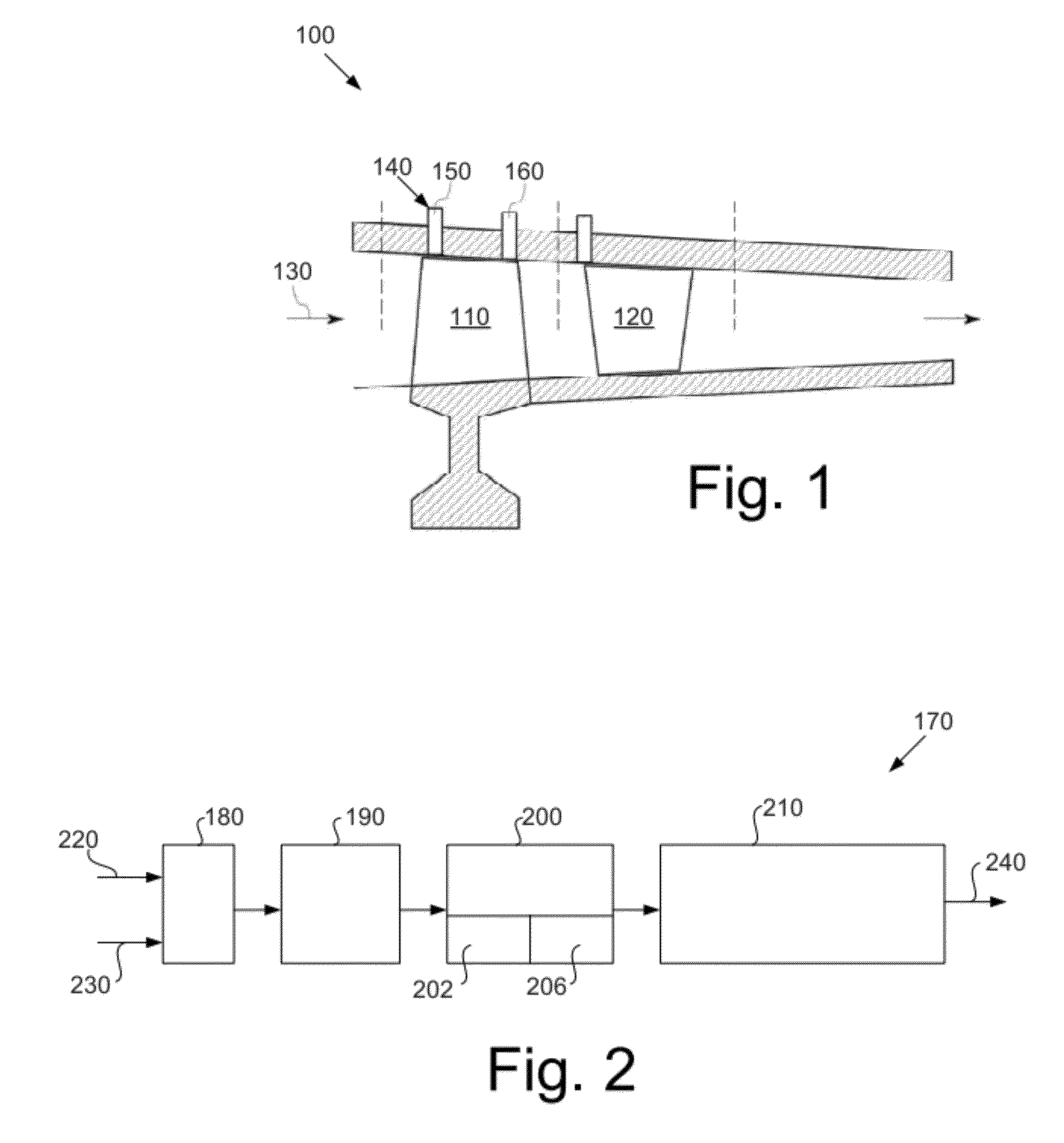
The present application relates generally to gas turbine engines and the like and more particularly relates to systems and methods for surge precursor detection and protection in a compressor by the measurement of power changes near the blade passing frequency. The compressor pressure ratio of a gas turbine engine generally is set at a pre-specified margin away from the surge/stall boundary (referred to as a surge margin or a stall margin), to avoid unstable compressor operation. In gas turbine engines used for power generation and other purposes, higher system efficiencies generally require higher compressor pressure ratios. Such higher pressure ratios, however, may necessitate a reduction in the operating surge/stall margin and hence a reduction in the response time if surge or stall conditions begin to develop. One approach to compressor surge or stall detection is to monitor the health of the compressor by measuring the airflow and the pressure rise through the compressor. These pressure variations may be attributed to a number of different causes such as, for example, unstable combustion, rotating stall, and surge events on the compressor itself. To determine these pressure variations, the magnitude and rate of change of the pressure rise through the compressor may be monitored. This approach, however, does not offer prediction capabilities of rotating stall or surge. Moreover, this approach may fail to offer information in real-time to a control system with sufficient lead time to deal proactively with such events. There is thus a desire for improved systems and methods for surge event precursor detection and protection. Such system and methods may determine a measure of surge likelihood in the compressor before an actual surge event itself with sufficient lead time to respond adequately so as to avoid damage thereto. The present application thus provides a method of monitoring a compressor. The method may include the steps of determining a blade passing frequency, determining a power indication for a number of frequencies above and below the blade passing frequency, determining a ratio between a maximum power indication and a minimum power indication for the frequencies for a number of predetermined time intervals, and analyzing the ratio for each predetermined time interval to predict a surge condition of the compressor. The present application further provides a compressor system. The system may include a speed sensor for obtaining a speed signal of a rotor, a pressure sensor for obtaining a number of dynamic pressure signals, and a controller configured to determine a blade passing frequency from the speed signal and to determine a surge indication signal based upon the dynamic power signals for a number of frequencies above and below the blade passing frequency. The present application further provides a method of monitoring a compressor for surge conditions therein. The method may include the steps of determining a blade passing frequency based upon a rotor speed signal, determining a power indication for a number of frequencies above and below the blade passing frequency based upon a number of dynamic pressure signals, determining a ratio between a maximum power indication and a minimum power indication for the frequencies for a predetermined time interval, analyzing the ratio for each predetermined time interval to predict a surge condition of the compressor, and providing a surge indication signal to the compressor. These and other features and improvements of the present application will become apparent to one of ordinary skill in the art upon review of the following detailed description when taken in conjunction with the several drawings and the appended claims. Generally described, a highly efficient gas turbine engine produces high electrical power output at a relatively low cost. The compressor in such a highly efficient gas turbine engine thus may be operated to produce a cycle pressure ratio that corresponds to a high firing temperature. As described above, the compressor may experience aerodynamic instabilities, such as, for example, stall and/or surge conditions, as the compressor is used to produce the high firing temperature or the high cycle pressure ratio. A compressor experiencing such stall and/or surge conditions may cause problems that may impact the components and the operational efficiency of the compressor and the overall gas turbine engine. Referring now to the drawings, in which like numerals refer to like elements throughout the several views, The compressor system 100 also may include a number of sensors 140 therein. The sensors 140 may sense a number of compressor operating parameters that may be indicative of stall and/or surge conditions. Specifically, the sensors 140 may include, for example, a speed sensor 150 configured to detect the rotational speed of the rotor 110 and a pressure sensor 160 configured to detect pressure dynamically about the rotor 110. Other types of sensors 140 and other types of operating parameters may be used and detected herein. The filter 180 receives these signals 220, 230 and may be configured to remove undesired components such as, for example, high frequency noise from the sensed parameters. Other types of filtering may be used herein. As will be described in more detail below, buffering (or storing) of the filtered data over a period of time may be performed over a sample rate during a moving window. In one example, the moving window occurs over a period of about eight (8) seconds. Other window lengths may be used herein. The storage medium 190 may be configured to store the filtered and/or buffered data. The signal processor 200 may be coupled to the storage medium 190 and configured to compute a Fast Fourier Transform analysis of the buffered data so as to determine a likelihood of surge. As will be described in more detail below, the signal processor 200 may include a speed-to-frequency converter 202 to convert the rotor speed signal 220 into a blade passing frequency. The blade passing frequency may be a product of the mechanical speed and the number of rotor blades. The signal processor 200 also may include a root mean square (RMS) converter 206. The RMS converter 206 may compute the root mean square of the dynamic pressure signals 230. The surge indicator 210 may be coupled to the signal processor 200 and configured to generate a surge indication signal 240 in response to the determination of a likelihood of surge. The surge indication signal 240 may be coupled to the overall compressor system 100 for corrective action such as shutdown and other actions in case of a detected likelihood of surge. At block 280, a window of the power indications for each frequency for about eight (8) seconds may be collected. This window thus is an eight (8) second time history of the power in each frequency about the blade passing frequency. At block 290, a minimum power indication and a maximum power indication is determined for each frequency in the window. In block 300, a ratio of the maximum power indication to the minimum power indication is determined for each frequency. At block 310, a maximum ratio of the ratios is determined. Depending upon the magnitude, the maximum ratio thus may serve as the surge indication signal 240. At block 320, the window may be updated at a rate of about once per second. Other update rates may be used. The Fast Fourier Transformation analysis 250 thus measures the ability of the controller 170 of the compressor system 100 to maintain a desired speed set point. As a surge condition begins to emerge, the controller 170 may lose the ability to maintain the set point as indicated by the larger changes in the power near the blade passing frequency. The Fast Fourier Transformation analysis 250 thus shows the stability, or the lack thereof, of the compressor system 100. The timely use of surge indication signal 240 therefore may avoid potential compressor damage. Advantageously, long term Fast Fourier Transform analyses of compressor operational parameters may alleviate shortcomings in present day analysis and operating procedures. Furthermore, Fast Fourier Transform analysis may aid in capturing accurately abnormal pressure perturbations and hence may minimize false pressure surges by way of using scaling factors and the like. Moreover, these aforementioned advantages may help in predicting the onset of surge and/or stall condition accurately, before the compressor surges or stalls, and thus protect the compressor from damage by way of controlling the operating parameters suitably based on the prediction. It should be apparent that the foregoing relates only to certain embodiments of the present application and that numerous changes and modifications may be made herein by one of ordinary skill in the art without departing from the general spirit and scope of the invention as defined by the following claims and the equivalents thereof. The present application provides a method of monitoring a compressor. The method may include the steps of determining a blade passing frequency, determining a power indication for a number of frequencies above and below the blade passing frequency, determining a ratio between a maximum power indication and a minimum power indication for the frequencies for a number of predetermined time intervals, and analyzing the ratio for each predetermined time interval to predict a surge condition of the compressor. 1. A method of monitoring a compressor, comprising:
determining a blade passing frequency; determining a power indication for a plurality of frequencies above and below the blade passing frequency; determining a ratio between a maximum power indication and a minimum power indication for the plurality of frequencies in a plurality of predetermined time intervals; and analyzing the ratio for each predetermined time interval to predict a surge condition of the compressor. 2. The method of 3. The method of 4. The method of 5. The method of 6. The method of 7. The method of 8. The method of 9. The method of 10. The method of 11. A compressor system, comprising:
a speed sensor for obtaining a speed signal of a rotor; a pressure sensor for obtaining a plurality of dynamic pressure signals; and a controller configured to determine a blade passing frequency from the speed signal and to determine a surge indication signal based upon the plurality of dynamic power signals for a plurality of frequencies above and below the blade passing frequency. 12. The system of 13. The system of 14. The system of 15. The system of 16. The system of 17. The system of 18. The system of 19. The system of 20. A method of monitoring a compressor, comprising:
determining a blade passing frequency based upon a rotor speed signal; determining a power indication for a plurality of frequencies above and below the blade passing frequency based upon a plurality of dynamic pressure signals; determining a ratio between a maximum power indication and a minimum power indication for the plurality of frequencies for a predetermined time interval; analyzing the ratio for each predetermined time interval to predict a surge condition of the compressor; and providing a surge indication signal to the compressor. TECHNICAL FIELD
BACKGROUND OF THE INVENTION
SUMMARY OF THE INVENTION
BRIEF DESCRIPTION OF DRAWINGS
DETAILED DESCRIPTION