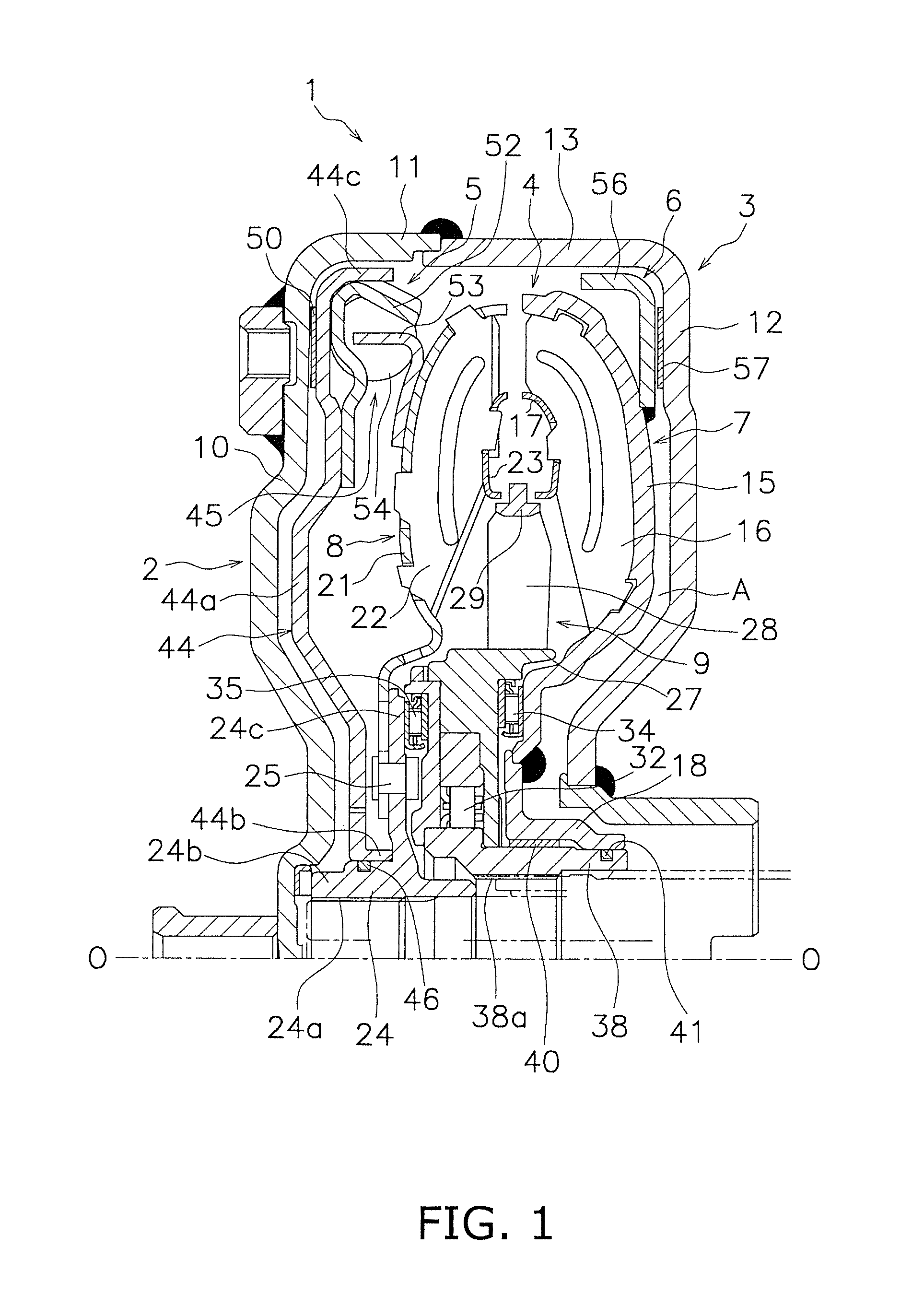
TORQUE CONVERTER
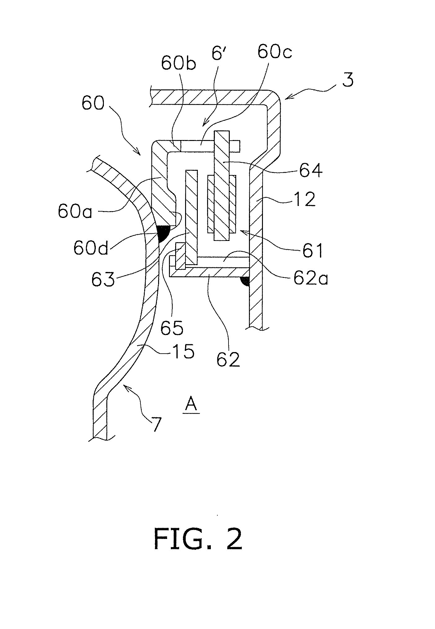
This U.S. national phase application claims priority to Japanese Patent Application No. 2009-242682 filed on Oct. 21, 2009. The entire disclosure of Japanese Patent Application No. 2009-242682 is hereby incorporated herein by reference. The present invention relates to a torque converter, particularly to a torque converter including a clutch part disposed between an input-side member and an impeller. The torque converters are devices configured to transmit torque from an engine towards a transmission through operating fluid filled in the inside thereof. The torque converters mainly include a front cover, an impeller and a turbine and a stator. The front cover is an annular member that torque is inputted from the engine. The impeller and the turbine are opposed to each other. Further, a stator is disposed between the inner periphery of the impeller and that of the turbine in order to regulate the flow of the operating fluid flowing from the turbine to the impeller. Further, torque inputted from the front cover into the impeller is transmitted to the turbine from the impeller through the operating fluid, and is then outputted from the turbine towards the transmission. The torque converters further include a lock-up clutch for enhancing torque transmission efficiency. The lock-up clutch is disposed in a space produced between the turbine and the front cover. The lock-up clutch is configured to directly transmit torque from the front cover to the turbine by mechanically coupling the front cover and the turbine in a region where a function of the torque converter is not required. Further, a type of torque converters as described in Patent Literature 1 has been produced so far. In the torque converters of this type, a housing is disposed for enclosing a torque converter main body together with a front cover and a clutch is disposed between the housing and an impeller. According to the torque converters of this type, engine load can be reduced and fuel consumption can be saved, for instance, by turning off the clutch when a vehicle is stopped while a shift lever is shifted in a drive range. PTL 1: Japan Laid-open Patent Application Publication No. JP-A-2004-301327 In the torque converter described in Patent Literature 1, a piston is disposed in a chamber produced between the impeller and the housing, and plural clutch plates are disposed between the piston and the housing. The inner periphery of the piston is engaged with a spline formed on an impeller hub. Therefore, the piston is relatively non-rotatable and axially movable with respect to the impeller. However, the construction described in Patent Literature 1 has a drawback that the axial size of the torque converter is increased. Specifically, the axially movable piston is required to be disposed between the rear face of the impeller and the housing. Therefore, the housing is bulged towards the transmission. Further, a pump casing is normally disposed between the impeller and the transmission. This further increases the axial size of the torque converter. Further, the construction described in Patent Literature 1 has another drawback that the torque converter structure is complicated due to sealing members required to be disposed on the inner periphery of the impeller hub and that of the piston. It is an object of the present invention to inhibit axial size increase and reduce the number of sealing members in a torque converter including a clutch disposed between an input-side member and an impeller. A torque converter according to a first aspect of the present invention includes a front cover, a housing, a torque converter main body, a lock-up clutch and an impeller clutch. The front cover receives a torque inputted therein from the engine. The housing is opposed to the front cover and includes an outer periphery coupled to an outer periphery of the front cover. The torque converter main body includes an impeller, a turbine and a stator. The torque converter body is disposed in a space enclosed by the front cover and the housing. The lock-up clutch is configured to directly transmit the torque from the front cover to the turbine. The impeller clutch is disposed between the housing and the impeller. The impeller clutch is configured to switch between allowing and preventing transmission of the torque. The impeller clutch includes a plate and a clutch part. The plate is fixed to a radially outer part of the impeller. The clutch part is disposed between the housing and the plate. In the torque converter, when the impeller clutch is turned on, torque from the engine is inputted into the torque converter main body from the front cover and is outputted from the turbine. When the impeller clutch is turned off, by contrast, torque from the front cover is transmitted to the housing but is not transmitted to the torque converter main body. Further, when the lock-up clutch is turned on, torque from the front cover is directly transmitted to the turbine through the lock-up clutch. According to the torque converter of the first aspect of the present invention, the impeller clutch is formed by the plate fixed to the radially outer part of the impeller and the clutch part. The radially outer part of the impeller is normally disposed further away from the transmission than the radially middle part thereof is. In other words, a space is produced between the radially outer part of the impeller and the housing. Therefore, the plate is fixed to the impeller using the space, and the impeller clutch is thus formed. With the structure, it is possible to inhibit axial size increase of the torque converter compared to the well-known torque converters. Further, the plate is fixed to the impeller and the impeller functions as a piston. Therefore, it is not required to provide a sealing member for the piston. In other words, the torque converter can be simply structured. A torque converter according to a second aspect of the present invention relates to the torque converter according to the first aspect of the present invention. In the torque converter, the clutch part includes a friction member disposed on either the housing or the plate. According to the torque converter of the second aspect of the present invention, the friction member is disposed between the plate and the housing. The impeller clutch is turned on (i.e., torque transmission allowing state) when the friction member is press-contacted with either of the plate and the housing. A torque converter according to a third aspect of the present invention relates to the torque converter according to the first aspect of the present invention. In the torque converter, the clutch part includes a first clutch plate and a second clutch plate. The first clutch plate is relatively non-rotatably and axially movably disposed with respect to the housing. The second clutch plate is relatively non-rotatably and axially movably disposed with respect to the plate. Further, the second clutch plate is configured to be press-contacted to the first clutch plate. According to the torque converter of the third aspect of the present invention, a plurality of friction surfaces can be formed and the torque transmission amount of the impeller clutch can be thereby increased. A torque converter according to a fourth aspect of the present invention relates to the torque converter according to the second aspect of the present invention. In the torque converter, the lock-up clutch includes a friction member. The friction member of the lock-up clutch has the same size as the friction member of the impeller clutch. According to the torque converter of the forth aspect of the present invention, the friction members can be compatibly used. A torque converter according to a fifth aspect of the present invention relates to the torque converter according to the first aspect of the present invention. In the torque converter, the impeller clutch is configured to switch between allowing and preventing transmission of the torque between the housing and the impeller including the plate fixed thereto in response to control of a hydraulic pressure in a chamber produced between the impeller and the housing. As described above, the present invention can inhibit axial size increase of, and simplify the structure of, a torque converter including an impeller clutch. The torque converter 1 mainly includes a front cover 2, a housing 3, a torque converter main body 4, a lock-up clutch 5 and an impeller clutch 6. The torque converter main body 4 includes an impeller 7, a turbine 8 and a stator 9. The front cover 2 can be attached to a component (not illustrated in the figures) disposed on the engine side (i.e., on the left side in The housing 3 is opposed to the front cover 2. The housing 3 includes a disc portion 12 and a tubular portion 13. The disc portion 12 is opposed to the disc portion 10 of the front cover 2. The tubular portion 13 is extended from the outer periphery of the disc portion 12 towards the engine. Further, the tip outer periphery of the tubular portion 13 of the housing 3 is fixed to the tip of the tubular portion 11 of the front cover 2 by means of welding. The torque converter main body 4 is disposed in a space enclosed by the front cover 2 and the housing 3. The impeller 7, forming a part of the torque converter main body 4, includes an impeller shell 15, a plurality of impeller blades 16 disposed within the impeller shell 15, and an impeller core 17. The impeller 7 further includes an impeller hub 18 fixed to the inner peripheral edge of the impeller shell 15. The turbine 8 is disposed in an opposed position to the impeller 7. The turbine 8 includes a turbine shell 21, a plurality of turbine blades 22 disposed within the turbine shell 21, and a turbine core 23. The turbine 8 further includes a turbine hub 24 for transmitting torque to the transmission (not illustrated in the figures). The turbine hub 24 includes a tubular portion 24 The stator 9 is configured to regulate the direction of the operating fluid returning from the turbine 8 to the impeller 7. The stator 9 is disposed between the inner periphery of the impeller 7 and that of the turbine 8. The stator 9 includes a stator shell 27, a plurality of stator blades 28 disposed radially outwards of the stator shell 27, and a stator core 29. Further, a one-way clutch 32 is disposed on the inner peripheral side of the stator 9. A first thrust bearing 34 is disposed axially between the stator shell 27 and the impeller shell 15. Further, a second thrust bearing 35 is disposed between the one-way clutch 32 and the flange 24 It should be noted that the one-way clutch 32 includes an inner race 38 formed in a tubular shape. The inner race 38 includes a spline hole 38 The lock-up clutch 5 is disposed in a space produced between the front cover 2 and the turbine 8. The lock-up clutch 5 mechanically couples the front cover 2 and the turbine 8. The lock-up clutch 5 mainly includes a piston 44 and an elastic coupling mechanism 45 for elastically coupling the piston 44 to the turbine 8. The piston 44 is a disc-shaped member made of sheet metal. The piston 44 is axially movable and rotatable in a space produced between the front cover 2 and the turbine 8. The piston 44 sections the space produced between the front cover 2 and the turbine 8 into two chambers, i.e., a chamber on the front cover 2 side and a chamber on the turbine 8 side. Further, the piston 44 is configured to be axially moved by means of pressure difference of the operating fluid between the chambers. The piston 44 includes a disc-shaped main body 44 A friction facing 50 is disposed on the engine side of the outer periphery of the main body 44 The elastic coupling mechanism 45 is disposed between the piston 44 and the turbine 8 for elastically coupling the piston 44 and the turbine 8 in the rotational direction. The elastic coupling mechanism 45 is formed by a retaining plate 52, a driven plate 53 and a plurality of coil springs 54 disposed between the retaining plate 52 and the driven plate 53. The impeller clutch 6 is disposed between the housing 3 and the impeller 7. The impeller clutch 6 is configured to switch between allowing and preventing torque transmission between the housing 3 and the impeller 7. The impeller clutch 6 includes a plate 56 and a friction facing 57. The plate 56 has a disc shape and the outer periphery thereof is bent towards the engine. Further, the inner peripheral edge of the plate 56 is fixed to the housing 3 side surface of the radially outer part of the impeller shell 15 by means of welding. More specifically, the impeller shell 15 has a circular-arc cross-section, as is obvious from It should be noted that the radially middle part of the impeller shell 15 is generally positioned in the same radial position as the center of a torus formed by the impeller 7, the turbine 8 and the stator 9. Therefore, the plate 56 is only required to be positioned radially outwards of the position. The friction facing 57 is disposed on the disc portion 12 of the housing 3 while being opposed to the plate 56. Torque is configured to be transmitted from the housing 3 to the impeller 7 when the friction facing 57 is press-contacted to the opposed surface (friction surface) of the plate 56. It should be noted that the size and the material of the friction facing 57 are identical to those of the friction facing 50 of the lock-up clutch 5. Therefore, the friction facing 57 is compatible with the friction facing 50. When torque is transmitted from the engine to the front cover 2 and the housing 3 while the lock-up clutch 5 is turned off (i.e., an uncoupled state) and the impeller clutch 6 is turned on (i.e., a coupled state), the torque is transmitted from the housing 3 to the impeller 7. The impeller 7 is thereby rotated and the operating fluid flows from the impeller 7 to the turbine 8. The turbine 8 is rotated by the flow of the operating fluid. The torque transmitted to the turbine 8 is transmitted to a main drive shaft of the transmission. It should be noted that a chamber A (see When the vehicle is set to be in an idling state, i.e., when the vehicle is stopped while the shift lever is operated in the drive range, the impeller clutch 6 is controlled to be turned off (i.e., the uncoupled state). Specifically, the operating oil is supplied to the chamber A between the housing 3 and the impeller 7. Accordingly, the impeller 7 and the plate 56 are moved away from the housing 3. In other words, press-contact of the plate 56 onto the friction facing 57 is released. Therefore, torque is prevented from being transmitted from the housing 3 to the impeller 7. Engine load is reduced under the condition, and fuel consumption can be thereby saved. When the travel speed of the vehicle becomes a predetermined speed or greater, the hydraulic pressure is controlled for moving the piston 44 towards the front cover 2 and the lock-up clutch 5 is accordingly turned on. In other words, the friction facing 50 attached to the piston 44 is press-contacted to the friction surface of the front cover 2. In this case, torque inputted into the front cover 2 is directly transmitted to the turbine 8 through the piston 44 and the elastic coupling mechanism 45. The torque transmitted to the turbine 8 is then outputted to the main drive shaft of the transmission. It should be noted that the impeller clutch 6 can be also used as a system for enhancing dynamic performance when being configured to be turned on in performing a brake operation and be turned off in performing an acceleration operation while the lock-up clutch 5 is turned on. The impeller clutch 6 is disposed on the radially outer part of the impeller 7. The impeller 7 and the housing 3 can be thereby disposed closer to each other. In other words, axial size increase of the torque converter can be inhibited. The impeller clutch 6 is formed by the plate 56 and the friction facing 57, and the plate 56 is fixed to the impeller shell 15 by means of welding. It is thereby possible to cause the impeller shell 15 (the impeller 7) to function as a piston of the impeller clutch 6. In other words, it is not required to additionally provide a piston. Further, it is not required to provide a sealing member required for such a piston to be additionally provided. Thus, the torque converter can be simply structured. (a) Similarly to the aforementioned exemplary embodiment, the plate 60 is fixed to a radially outer part of the impeller shell 15, and includes a disc-shaped fixation portion 60 The clutch part 61 includes an input-side plate 62 fixed to the disc portion of the housing 3, a first clutch plate 63 and a second clutch plate 64. The input-side plate 62 has a tubular shape, and one end thereof is fixed to the disc portion 12 of the housing 3 by means of welding. Further, the input-side plate 62 includes a spline 62 The first clutch plate 63 has a disc shape and includes a spline on the inner periphery thereof. The spline of the first clutch plate 63 is engaged with the spline 62 Similarly to the first clutch plate 63, the second clutch plate 64 has a disc shape. The second clutch plate 64 includes a plurality of lugs on the outer periphery thereof. The lugs are engaged with the slits 60 In the aforementioned impeller clutch 6′, the first clutch plate 63 is pressed by the pressure protrusion 60 When the hydraulic pressure is increased in the chamber A, by contrast, the impeller 7 and the plate 60 are moved away from the housing 3 and press-contact between the first clutch plate 63 and the second clutch plate 64 is released. Accordingly, torque is prevented from being transmitted from the housing 3 to the impeller 7. In other words, the impeller clutch 6′ is turned off. The present exemplary embodiment can also achieve advantageous effects similar to those achieved by the aforementioned exemplary embodiment. In addition, two friction surfaces are herein formed. Therefore, the torque transmission amount of the impeller clutch can be increased. (b) In the exemplary embodiment illustrated in According to the torque converter of the present invention, it is possible to inhibit axial size increase thereof, and simultaneously, simplify the construction thereof. It is an object of the present invention to inhibit axial size increase and simplify a structure of a torque converter including a clutch disposed between a front cover and an impeller. The torque converter includes a front cover, a housing, a torque converter main body, a lock-up clutch and an impeller clutch. The housing includes an outer periphery coupled to that of the front cover. The torque converter main body, including an impeller, is disposed in a space enclosed by the front cover and the housing. The impeller clutch is disposed between the housing and the impeller for allowing/preventing torque transmission. Further, the impeller clutch includes a plate fixed to a radially outer part of the impeller and a friction facing disposed between the housing and the plate. 1. A torque converter, comprising:
a front cover receiving a torque inputted therein from an engine; a housing opposed to the front cover, the housing including an outer periphery coupled to an outer periphery of the front cover; a torque converter main body including an impeller, a turbine and a stator, the torque converter main body disposed in a space enclosed by the front cover and the housing; a lock-up clutch configured to directly transmit the torque from the front cover to the turbine; and an impeller clutch disposed between the housing and the impeller, the impeller clutch configured to allow or prevent transmission of the torque, wherein the impeller clutch includes: a plate fixed to a radially outer part of the impeller; and a clutch part disposed between the housing and the plate. 2. The torque converter recited in 3. The torque converter recited in 4. The torque converter recited in wherein the lock-up clutch includes a friction member, and the friction member of the lock-up clutch has the same size as the friction member of the impeller clutch. 5. The torque converter recited in one of CROSS-REFERENCE TO RELATED APPLICATIONS
TECHNICAL FIELD
BACKGROUND ART
CITATION LIST
Patent Literature
SUMMARY
Technical Problems
Solution to Problems
Advantageous Effects of the Invention
BRIEF DESCRIPTION OF THE DRAWINGS
DETAILED DESCRIPTION OF EXEMPLARY EMBODIMENTS
Entire Structure
Front Cover
Housing
Torque Converter Main Body
Lock-up Clutch
Impeller Clutch
Actions
Features
Other Exemplary Embodiments
INDUSTRIAL APPLICABILITY