STRAP CLAMP WITH TRANSVERSE ORIENTED CAM DOOR
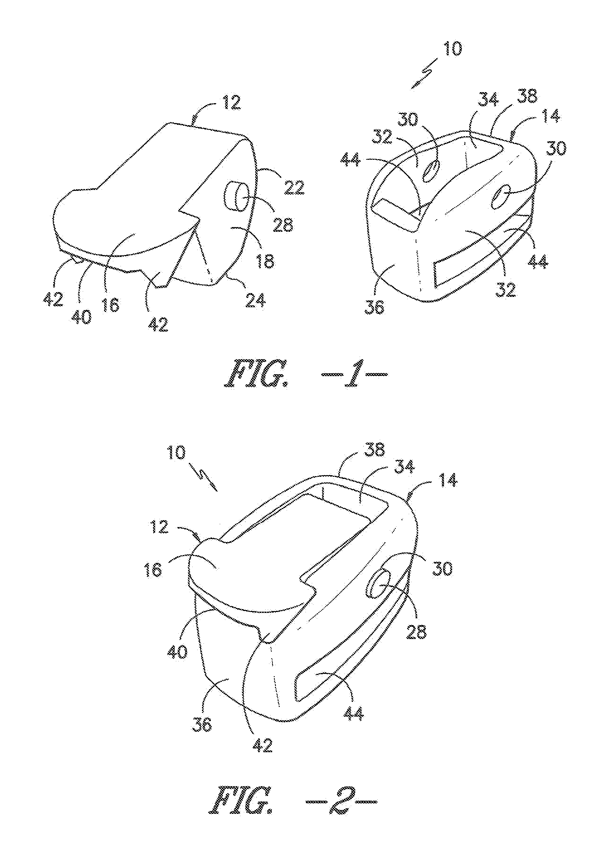
This non-provisional application claims the benefit of and priority from U.S. Provisional Application 61/439,694 filed Feb. 4, 2011. The contents of such prior application are hereby incorporated by reference in their entirety as if fully set forth herein. The present invention relates generally to clamps, and more particularly to clamps adapted for sliding engagement and lock-down of straps or other webbing elements. Such clamps may be used in environments such as helmets, backpacks, clothing and the like. Clamps that slidingly engage webbing segments and which may be selectively locked down relative to such webbing segments are known. Such prior clamps typically incorporate a base frame adapted to receive webbing segments such that the base frame can slide along the length of the webbing segments and such that the webbing segments can be adjusted relative to one another by being selectively pulled through the base frame. Some prior clamps have incorporated lock-down elements in the form of camming doors which are held within a carrier frame in overlying relation to the webbing segments. However, in known prior clamps having hinging lock-down camming doors, the doors have typically been oriented to rotate on an arc which is generally aligned with the travel direction of the webbing segments. Such an orientation minimizes the potential for tilting displacement of the camming door when the webbing segments are pulled. The present invention departs from prior designs by providing a webbing clamp incorporating a hollow base frame adapted to receive elongated webbing segments in threaded relation through a pair of opposing slot openings and a hinging camming door structure rotatably mounted within the base frame about an axis of rotation. The camming door structure includes a lever projection for user engagement and a camming ear portion extending below the lever projection for disposition at the interior of the base frame. The camming door structure is mounted transverse to the threading direction of the webbing elements and rotates about an axis generally aligned with the threading direction of the webbing elements. Upon closing the hinging door structure, the camming ear portion engages the webbing elements in a compressing manner thereby blocking relative sliding action of the webbing elements within the clamp. In accordance with one exemplary aspect, the present invention provides an adjustable webbing clamp adapted to selectively slide along one or more elongate webbing segments and to lock such webbing segments in place at the interior of the webbing clamp. The webbing clamp includes a base frame having a plurality of walls at least partially surrounding an interior cavity. A door acceptance opening is disposed between a pair of opposed lateral sidewalls. Each of the lateral sidewalls includes a webbing slot extending through the sidewall. The webbing slots are adapted to receive the elongate webbing segments in threaded relation in a travel path across the interior cavity. The webbing clamp further includes a camming door adapted for receipt within the door acceptance opening. The camming door includes a lever portion and a camming ear adapted to be received within the interior cavity. The camming door is rotatably mounted at the base frame along an axis of rotation oriented in transverse relation to the lateral sidewalls and in substantial alignment with the travel path of the webbing segments. Upon rotating the lever portion to a raised position away from the base frame, the camming ear is raised away from the travel path of the webbing segments and upon rotating the lever portion towards the base frame, the camming ear is lowered into compressing, clamping relation against the webbing segments. A method of selectively clamping webbing is also provided. Other features and advantages of the invention will become apparent to those skilled in the art upon review of the following detailed description, and drawings in which like numbers are used to designate like features. Before the embodiments of the intention are explained in detail, it is to be understood that the invention is not limited in its application to the details of construction and the arrangements of the components set forth in the following description or illustrated in the drawings. The invention is capable of other embodiments and of being practiced or being carried out in various ways. Also, it is understood that the phraseology and terminology used herein are for the purpose of description and should not be regarded as limiting. The use herein of “including”, “comprising” and variations thereof is meant to encompass the items listed thereafter and equivalents thereof, as well as additional items and equivalents thereof. Reference will now be made to the drawings, wherein to the extent possible, like elements are designated by like reference numerals in the various views. Referring now to As best illustrated through joint reference to As noted previously, the camming door 12 is adapted to be supported in rotatable relation within the base frame 14. By way of example only, and not limitation, in the illustrated exemplary construction the camming ear 18 may include outwardly projecting pins 28 oriented in aligned relation to one another on opposing sides of the camming ear 18. In the exemplary embodiment, the base frame 14 has a generally bin configuration with an open top and including a pair of aligned through holes 30 extending through opposing lateral sidewalls 32. As may be understood through joint reference to As shown, in the exemplary construction, the lever portion 16 may include a relatively wide distal lip 40 which extends beyond the first end wall 36 in the assembled condition ( In the illustrated exemplary embodiment, the base frame 14 includes a pair of webbing slots 44 extending through the opposing lateral walls 32 at an elevation below the through holes 30. In practice, these webbing slots are adapted to receive one or more webbing segments 26 which extend in threaded relation through the webbing slots in transverse orientation to the base frame 14 and to the rotational direction of the camming door 12. That is, the length dimension of the webbing segments 26 is oriented in general alignment with the axis of rotation 35 of the camming door 12. As shown in In the illustrated exemplary embodiment, the webbing slots 44 are oriented in planes which are substantially perpendicular to the axis of rotation 35 of the camming door as defined by the pins 28. Thus, the camming door 12 rotates through an arc which is transverse to the travel direction and length dimension of the webbing segments 26. Due to this orientation, when the webbing clamp 10 is in the closed and locked condition as illustrated in Referring now jointly to When the user initially puts on the helmet 50, it is generally desirable for the chinstrap 52 to be relatively loose. Once the helmet 50 is adjusted to the proper position, it is then desirable to tighten the chinstrap 52 to hold the helmet 50 in place. As shown through joint reference to Once the desired tightness has been achieved, the webbing clamp 10 may then be locked down as shown in Variations and modifications of the foregoing are within the scope of the present invention. It is understood that the invention disclosed and defined herein extends to all alternative combinations of two or more of the individual features mentioned or evident from the text and/or drawings. All of these different combinations constitute various alternative aspects of the present invention. The embodiments described herein explain the best modes known for practicing the invention and will enable others skilled in the art to utilize the invention. The claims are to be construed to include alternative embodiments to the extent permitted by the prior art. A webbing clamp incorporating a hollow base frame adapted to receive elongated webbing segments in threaded relation through a pair of opposing slot openings and a hinging camming door structure rotatably mounted within the base frame about an axis of rotation. The camming door structure includes a lever projection for user engagement and a camming ear portion extending below the lever projection for disposition at the interior of the base frame. The camming door structure is mounted transverse to the threading direction of the webbing segments and rotates about an axis generally aligned with the threading direction of the webbing segments. Upon closing the hinging door structure, the camming ear portion engages the webbing segments in a compressing manner thereby blocking relative sliding action with the webbing clamp. 1. An adjustable webbing clamp adapted to selectively slide along one or more elongate webbing segments and to lock such webbing segments in place at the interior of the webbing clamp, the webbing clamp comprising:
a base frame including a plurality of walls at least partially surrounding an interior cavity, wherein a door acceptance opening is disposed between a pair of opposed lateral sidewalls, and wherein each of the lateral sidewalls includes a webbing slot extending through the sidewall, the webbing slots being adapted to receive said one or more elongate webbing segments in threaded relation in a travel path across the interior cavity; and a camming door adapted for receipt within the door acceptance opening, the camming door including a lever portion and a camming ear adapted to be received within the interior cavity, wherein the camming door is rotatably mounted at the base frame along an axis of rotation oriented in transverse relation to the lateral sidewalls and in substantial alignment with the travel path of the webbing segments such that upon rotating the lever portion to a raised position away from the base frame, the camming ear is raised away from the travel path of the webbing segments and upon rotating the lever portion towards the base frame, the camming ear is lowered into compressing, clamping relation against the webbing segments. 2. The adjustable webbing clamp as recited in 3. The adjustable webbing clamp as recited in 4. The adjustable webbing clamp as recited in 5. The adjustable webbing clamp as recited in 6. The adjustable webbing clamp as recited in 7. The adjustable webbing clamp as recited in 8. The adjustable webbing clamp as recited in 9. The adjustable webbing clamp as recited in 10. The adjustable webbing clamp as recited in 11. The adjustable webbing clamp as recited in 12. The adjustable webbing clamp as recited in 13. An adjustable webbing clamp adapted to selectively slide along one or more elongate webbing segments and to lock such webbing segments in place at the interior of the webbing clamp, the webbing clamp comprising:
a base frame including a plurality of walls at least partially surrounding an interior cavity, wherein a door acceptance opening is disposed between a pair of opposed lateral sidewalls, and wherein each of the lateral sidewalls includes a webbing slot extending through the sidewall, the webbing slots being disposed in substantially opposing relation to one another and adapted to receive said one or more elongate webbing segments in threaded relation in a travel path across the interior cavity, each of the lateral sidewalls further including a through hole at an elevation above the webbing slots; and a camming door adapted for receipt within the door acceptance opening, the camming door having a substantially “b” shaped profile including a lever portion including a distal lip adapted to project outwardly from the base frame and a camming ear adapted to be received within the interior cavity, wherein the camming door is rotatably mounted at the base frame along an axis of rotation oriented in transverse relation to the lateral sidewalls and in substantial alignment with the travel path of the webbing segments, the axis of rotation being defined by a pair of pins projecting outwardly from opposing sides of the camming ear, the pins being adapted for receipt within opposing through holes upon insertion of the camming ear into the interior cavity, the camming ear including a rear surface facing away from the distal lip and a substantially flat lower edge defining a compression foot disposed at an elevation below the rear surface, the lower edge being spaced apart from the axis of rotation at a distance which is greater than the distance between the axis of rotation and the rear surface such that upon rotating the distal lip away from the base frame, the camming ear is raised away from the travel path of the webbing segments with the rear surface being disposed in opposing, non-contacting relation above the webbing segments and upon rotating the distal lip towards the base frame, the lower edge of the camming ear is lowered into compressing, clamping relation against the webbing segments. 14. The adjustable webbing clamp as recited in 15. The adjustable webbing clamp as recited in 16. The adjustable webbing clamp as recited in 17. The adjustable webbing clamp as recited in 18. The adjustable webbing clamp as recited in 19. The adjustable webbing clamp as recited in 20. A method of selectively clamping one or more elongate webbing segments in place at the interior of the webbing clamp, the method comprising:
providing a base frame including a plurality of walls at least partially surrounding an interior cavity, wherein a door acceptance opening is disposed between a pair of opposed lateral sidewalls, and wherein each of the lateral sidewalls includes a webbing slot extending through the sidewall, the webbing slots being adapted to receive said one or more elongate webbing segments in threaded relation in a travel path across the interior cavity; providing a camming door received within the door acceptance opening, the camming door having a lever portion and a camming ear adapted to be received within the interior cavity, wherein the camming door is rotatably mounted in the base frame along an axis of rotation oriented in transverse relation to the lateral sidewalls and in substantial alignment with the travel path of the webbing segments such that upon rotating the lever portion to a raised position away from the base frame, the camming ear is raised away from the travel path of the webbing segments and upon rotating the lever portion towards the base frame, the camming ear is lowered into compressing, clamping relation against the webbing segments; threading or more elongate webbing segments through the webbing slots and across the interior cavity; and selectively manipulating the lever portion to clamp and release the webbing segments.CROSS-REFERENCE TO RELATED APPLICATIONS
FIELD OF THE INVENTION
BACKGROUND OF THE INVENTION
SUMMARY OF THE INVENTION
BRIEF DESCRIPTION OF THE DRAWINGS
DETAILED DESCRIPTION OF THE PREFERRED EMBODIMENTS