RECHARGEABLE BATTERY
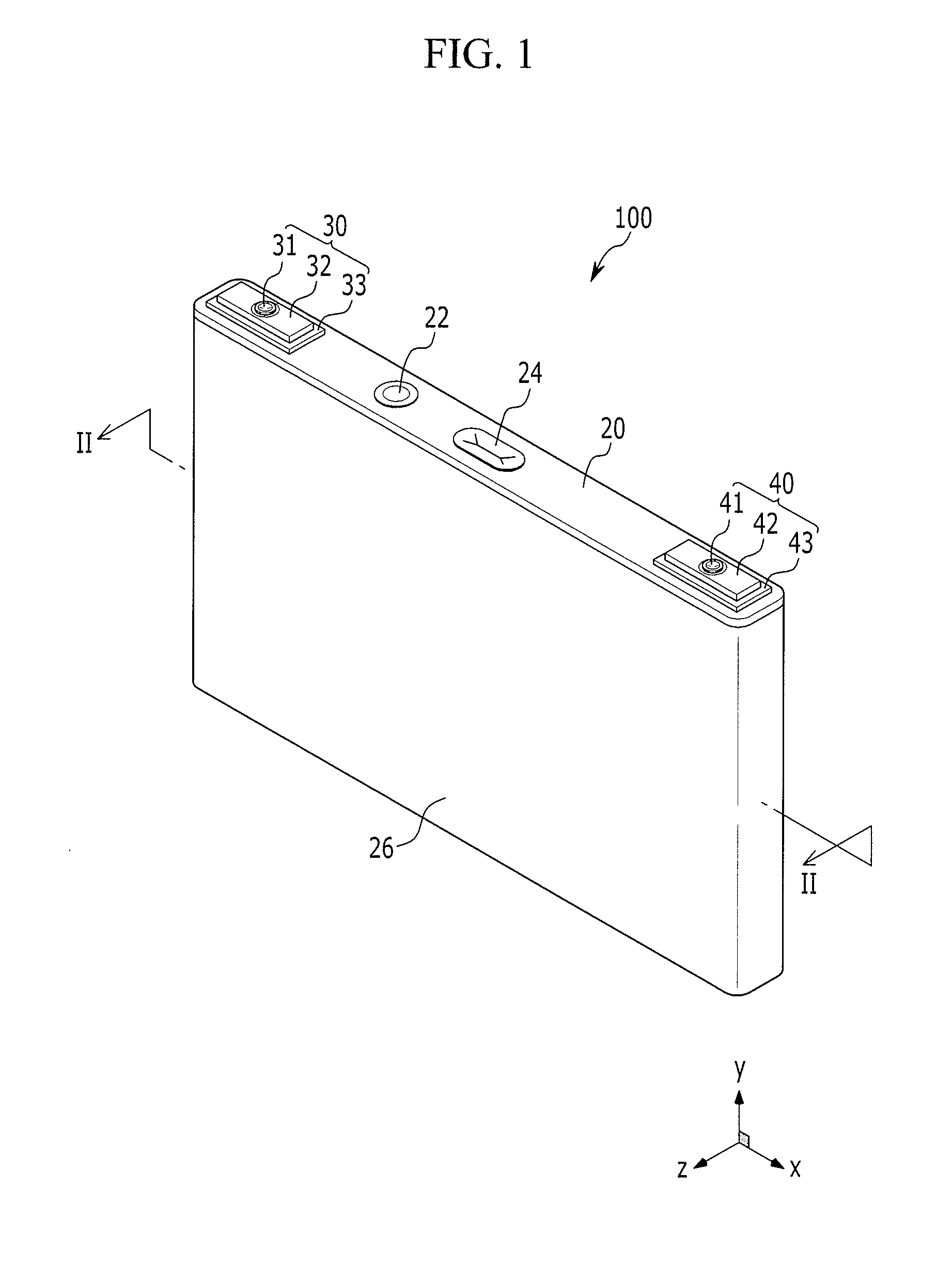
This application claims the benefit of and priority to U.S. Provisional Application No. 61/503,160, filed on Jun. 30, 2011, in the United States Patent and Trademark Office, the disclosure of which is incorporated herein in its entirety by reference. 1. Field Embodiments of the present invention generally relate to a rechargeable battery, and more particularly, to a rechargeable battery having an improved gasket and terminal structure. 2. Description of the Related Art A rechargeable battery is a battery that can be recharged, unlike a primary battery that cannot be recharged. A low-capacity rechargeable battery may be used for small portable electronic devices such as a mobile phone, a notebook computer, and a camcorder and a large-capacity battery may be used as a power supply for driving a motor such as a hybrid or electric car or a large-capacity power storage device. Recently, a high-output rechargeable battery using a non-aqueous electrolyte solution having high energy density has been developed. The high-output rechargeable battery is configured of a large-capacity battery module in which a plurality of rechargeable batteries are connected to each other in series so as to be used to motors for devices requiring large power, for example, an electric car, a hybrid car, or the like. The rechargeable battery may be configured to have a cylindrical shape, a square shape, or the like. However, in some circumstances, the electrolyte solution in a case of the rechargeable battery infiltrates between an electrode terminal and a cap plate, thereby causing an electrical short between the electrode terminal and the cap plate. In addition, the electrolyte solution in the case of the rechargeable battery may leak outside of the case. The above information disclosed in this Background section is only for enhancement of understanding of the background of the described technology and therefore it may contain information that does not form the prior art that is already known in this country to a person of ordinary skill in the art. Aspects of embodiments of the present invention are directed toward a rechargeable battery capable of preventing or reducing the likelihood of an electrical short between an electrode terminal and a cap plate by blocking an electrolyte solution in a case of the rechargeable battery from infiltrating between the electrode terminal and the cap plate. In addition, aspects of embodiments of the present invention are directed toward a rechargeable battery capable of preventing or protecting an electrolyte solution from being leaked to the outside of a case. According to an embodiment of the present invention, a rechargeable battery includes: an electrode assembly in a case; a cap plate coupled to an opening of the case; a rivet electrically connected to the electrode assembly, the rivet including: a first rivet flange; and a second rivet flange; and a gasket between the rivet flange and the cap plate, the gasket including: a first gasket flange configured to be coupled with the first rivet flange; and a second gasket flange configured to be coupled with the second rivet flange. The first gasket flange may be greater than or equal to the first rivet flange in size. The second gasket flange may be greater than or equal to the second rivet flange in size. The rivet may further include a pillar part extending through the cap plate. The gasket may have a through hole and the pillar part of the rivet may extend through the through hole of the gasket. The first rivet flange may extend in a first direction and a second direction perpendicular to the first direction, the second rivet flange may extend in the second direction, the second rivet flange may extend from a side edge of the first rivet flange, the first gasket flange may extend in the first direction and the second direction, the second gasket flange may extend in the second direction, and the second gasket flange may extend from a side edge of the first gasket, the gasket may include a gasket body extending in a third direction perpendicular to the first and second directions, and the through hole of the gasket may be formed through the gasket body in the third direction. The rechargeable battery may further include an insulating member having a through hole, and the gasket body may extend through the through hole of the insulating member. The first rivet flange may extend in a first direction and a second direction perpendicular to the first direction, the second rivet flange may extend in the second direction, the second rivet flange may extend from a side edge of the first rivet flange, the first gasket flange may extend in the first direction and the second direction, the second gasket flange may extend in the second direction, and the second gasket flange may extend from a side edge of the first gasket. The second gasket flange may include a bent portion extending in a third direction perpendicular to the first and second directions and covering an end of the second rivet flange. The rivet may further include: a third rivet flange extending in the second direction, the third rivet flange extending from another side edge of the first rivet flange facing oppositely away from the side edge from which the second rivet flange extends. The gasket may further include: a third gasket flange extending in the second direction, the third gasket flange extending from another side edge of the first gasket flange facing oppositely away from the side edge from which the second gasket flange extends and configured to be coupled with the third rivet flange. The third gasket flange may be greater than or equal to the third rivet flange in size. The third gasket flange may include a bent portion extending in a third direction perpendicular to the first and second directions and covering an end of the third rivet flange. The gasket may further include a rivet flange coupling part including: a first rivet flange coupling lip extending from the first gasket flange in a third direction perpendicular to the first and second directions; and a second rivet flange coupling lip extending from the second gasket flange in the third direction. The second gasket flange may be thinner than the first gasket flange. The rechargeable battery may further include an insulating member having a coupling groove configured to house the rivet flange and the gasket, wherein the insulating member may be between the gasket and the cap plate, and the gasket and the first and second rivet flanges are between the cap plate and the insulating member. The rechargeable battery may further include a current collector, wherein the rivet may be electrically coupled to the electrode assembly via the current collector, the current collector comprising a terminal coupling part and an electrode coupling part. The insulating member may include a coupling groove configured to house the terminal coupling part between the coupling groove and the rivet flange. The insulating member may further include a coupling ring at a side edge of the insulating member, the coupling ring encircling a portion of the electrode coupling part. The cap plate may include a plurality of protruding grooves and the insulating member may include fixing protrusions configured to be respectively coupled with the protruding grooves. Embodiments of the present invention will be described more fully hereinafter with reference to the accompanying drawings, in which exemplary embodiments of the invention are shown. As those skilled in the art would realize, the described embodiments may be modified in various different ways, all without departing from the spirit or scope of the present invention. In the drawings, dimensions of layers, regions, etc., are exaggerated for clarity. It will be understood that when one layer or one element is considered to as being “on” another element, it can be directly on the other element or intervening elements may also be present therebetween. Further, it will be understood that when one layer or one element is considered to as being “under” another element, it can be directly on (under) the other element or at least one intervening element may also be present therebetween. In addition, it will be understood that when one layer is considered to as being “between” two layers, it can be a unique layer between two layers or at least one other layer may also be present therebetween. Like reference numerals designate like elements throughout the specification and the drawings. Referring to The rechargeable battery 100 according to one exemplary embodiment is a lithium ion rechargeable battery. Herein, a squared rechargeable battery will be described by way of example. However, embodiments of the present invention are not limited thereto and the present invention may be applied to a battery such as a lithium polymer battery, or the like. In addition, the first electrode 11 may be a negative electrode and the second electrode 12 may be a positive electrode, or vice versa. However, for the sake of convenience, in the exemplary embodiment, the first electrode 11 and the second electrode 12 will be described instead of the negative electrode and the positive electrode, respectively, but embodiments of the present invention are not limited thereto. The electrode assembly 10 is formed by winding the first electrode 11, the second electrode 12, and the separator 13 together to form a jelly roll structure. The first electrode 11 and the second electrode 12 each include a current collector formed of a thin metal foil and an active material coated on a surface of the current collector. In addition, the first electrode 11 and the second electrode 12 may be partitioned into a coated part in which an active material is coated on the current collector and a first electrode non-coated part 11 a and a second electrode non-coated part 12 However, embodiments of the present invention are not limited thereto. The above-described electrode assembly 10 may be formed in a stacked structure, having the separator 13 between the first electrode 11 and the second electrode 12 formed of a plurality of sheets. The first electrode non-coated part 11 The case 26 is formed in an approximately rectangular parallelepiped (or rectangular prism or cuboid) shape, and one surface thereof is provided with an opened opening. However, embodiments of the present invention are not limited thereto, and the case may be formed in various suitable shapes, such as a cylindrical shape, a pouch shape, or the like. According to one embodiment of the present invention, the cap plate 26 is formed of a thin plate and is coupled with the opening of the case 26 to seal the opening. Further, the cap plate 20 is provided with an electrolyte solution inlet 21 through which the electrolyte solution may be injected into the sealed case 26, wherein the electrolyte solution inlet 21 is sealed by a sealing closure 22 after the electrolyte solution is injected. In addition, the cap plate 20 is provided with a vent hole 23 mounted with a vent plate 24 which is adapted to fracture when an internal pressure of the sealed case 26 exceeds a pressure (e.g., a set pressure). The first and second terminal parts 30 and 40 include first and second rivets 31 and 41, first and second terminal plates 32 and 42, a first terminal insulating member 33 disposed between the first and second terminal plates 32 and 42 and the cap plate 20, a conductive connection member 43, and first and second gaskets 34 and 44. In this configuration, the first and second rivets 31 and 41 include first and second pillar parts 31 According to one exemplary embodiment of the present invention, because the cap plate 20 is electrically connected to the second terminal part 40 by the conductive connection member 43, the cap plate 20 may have the polarity of the positive electrode or the negative electrode. Further, the first and second electrode current collecting members 50 and 70 include first and second electrode coupling parts 51 and 71 (see, e.g., In this configuration, according to one exemplary embodiment of the present invention, the structure of the first and second terminal parts 30 and 40, and the structure of the first and second electrode current collecting members 50 and 70 and first and second insulating members 60 and 80 are substantially the same. Therefore, the description of the second terminal part 40, the second electrode current collecting member 70, and the second insulating member 80 will be omitted. However, the first terminal part 30 according to one exemplary embodiment of the present invention may include a cylindrically-shaped terminal rather than a plate-shaped terminal. Instead of the conductive connection member 43, an insulating connection member may be disposed between the cap plate 20 and the second rivet 41. Therefore, in some embodiments of the present invention, the cap plate 20 is not be electrically connected to the second terminal part 40. Referring to In more detail, the rivet flange part 31 In addition, the first gasket 34 according to the exemplary embodiment may include a body 34 In more detail, the gasket flange part 34 In addition, a first insulating member 60 according to one embodiment of the present invention includes a coupling groove 61, a plurality of fixing protrusions 62 fixed to a plurality of protruding grooves 25 formed on the cap plate 20, and a through hole 63 through which the first rivet 31 penetrates. In this configuration, the coupling groove 61 may be formed on one surface of the first insulating member 60 opposite to (e.g., facing away from) the electrode assembly 10, as shown in Moreover, the first electrode current collecting member 50 may include a first electrode coupling part 51 and a first terminal coupling part 52 that are coupled with the first electrode 11. Hereinafter, the coupling relationship between the first rivet 31 and the first gasket 34 according to the exemplary embodiment will be described in more detail. In the first insulating member 60, the fixing protrusions 62 may be fixed to the protrusion grooves 25 formed on the cap plate 20. Further, the first gasket 34 may be inserted into the coupling groove 61 formed on the bottom of the first insulating member 60. In this configuration, the body 34 In this case, the second gasket flange part 342 In addition, the pillar part 31 Therefore, the first rivet flange 311 In this configuration, the size of the first gasket flange 341 Consequently, the size of the gasket flange part 34 Referring again to Therefore, in one embodiment of the present invention, the first insulating member 60 is disposed between the electrode current collector 10 and the cap plate 20 by fixing the rivet flange part 31 The electrolyte solution injected into the case of the rechargeable battery 100 according to one exemplary embodiment may permeate into the coupling groove 61 of the first insulating member 60 or between the first insulating member 60 and the cap plate 20, such that an electrical short is formed between the cap plate 20 and the first rivet 31. In this case, since the size of the gasket flange part 34 Therefore, it is possible to prevent or reduce the risk of the electrolyte solution in the case 26 from leaking outside of the case 26. In addition, because the second gasket flange 342 Therefore, the adhesion between the rivet flange part 31 In this case, the rechargeable battery 101 according to the exemplary embodiment of Referring to In more detail, the gasket flange part 34 In this configuration, the first gasket flange 341 Further, the second gasket flange 342 In this configuration, the end of the second gasket flange 342 Therefore, the second and third gasket flanges 342 As a result, it is possible to further improve the adhesion between the rivet flange 31 In addition, according to one exemplary embodiment, because the entire path through which the electrolyte solution permeates into the first insulating member 60 to reach the cap plate 20 is increased, the risk of an electrical short between the cap plate 20 and the first rivet 31 due to the electrolyte solution can be reduced. The rechargeable battery 200 according to the second exemplary embodiment has substantially the same structure as the rechargeable battery 100 according to the first exemplary embodiment, except for the first gasket 34″, and therefore, the description of structures that are substantially the same will be omitted. Referring to According to the exemplary embodiment, the gasket flange part 34 However, the first gasket flange part 341 Further, a rivet flange coupling lip 34 In more detail, the rivet flange coupling lip 34 Therefore, the first rivet flange 311 Therefore, according to the exemplary embodiment, the rivet flange 31 Therefore, the adhesion between the gasket flange part 34 As a result, it is possible to prevent or reduce the risk of the electrolyte solution in the case 26 from being leaked outside of the case 26. In addition, because the entire path through which the electrolyte solution must permeate into the first insulating member 60 to reach the cap plate 20 is increased, the risk of an electrical short between the cap plate 20 and the first rivet 31 due to the electrolyte solution may be reduced. In this embodiment, a rechargeable battery 300 according to the exemplary embodiment has substantially the same structure as the rechargeable battery 200 according to the second exemplary embodiment, except for a first insulating member 90, and therefore, the description of the substantially similar structures will be omitted. Referring to In this configuration, the coupling groove 91 according to the third exemplary embodiment is formed on a surface of the first insulating member 90 that is opposite to (e.g., facing) the cap plate 20. Therefore, as shown in In addition, the first rivet 31 and the first gasket 34″ are sequentially stacked in the coupling groove 91. Therefore, it is possible to more easily couple the first electrode current collecting member 50, the first rivet 31, and the first gasket 34″. Moreover, because the first electrode coupling part 51 of the first electrode current collecting member 50 is received in the coupling groove 91, the first insulating member 90 according to the third exemplary embodiment may prevent or mitigate the contact between the first electrode coupling part 51 and the electrolyte solution. Therefore, it is possible to prevent or reduce the risk of an electrical short between the cap plate 20 and the first rivet 31. In this case, a rechargeable battery 301 according to the modified third exemplary embodiment has substantially the same structure as the rechargeable battery 300 according to the third exemplary embodiment, except for a first electrode current collecting member coupling ring 93 of the first insulating member 90 and therefore, the description of substantially similar structures will be omitted. Referring to Therefore, one side of the first terminal coupling part 52 of the first electrode current collecting member 50 is fixed by the first electrode current collecting member coupling ring 93. As a result, the first electrode current collecting member 50 may be more stably coupled with the first insulating member 90 by the first electrode current collecting member coupling ring 93. As shown in While this disclosure has been described in connection with what is presently considered to be practical exemplary embodiments, it is to be understood that the invention is not limited to the disclosed embodiments, but, on the contrary, is intended to cover various modifications and equivalent arrangements included within the spirit and scope of the appended claims. A rechargeable battery includes: an electrode assembly in a case; a cap plate coupled to an opening of the case; a rivet electrically connected to the electrode assembly, the rivet including: a first rivet flange; and a second rivet flange; and a gasket between the rivet flange and the cap plate, the gasket including: a first gasket flange configured to be coupled with the first rivet flange; and a second gasket flange configured to be coupled with the second rivet flange. 1. A rechargeable battery comprising:
an electrode assembly in a case; a cap plate coupled to an opening of the case; a rivet electrically connected to the electrode assembly, the rivet comprising:
a first rivet flange; and a second rivet flange; and a gasket between the rivet flange and the cap plate, the gasket comprising:
a first gasket flange configured to be coupled with the first rivet flange; and a second gasket flange configured to be coupled with the second rivet flange. 2. The rechargeable battery of 3. The rechargeable battery of 4. The rechargeable battery of 5. The rechargeable battery of 6. The rechargeable battery of 7. The rechargeable battery of wherein the gasket body extends through the through hole of the insulating member. 8. The rechargeable battery of 9. The rechargeable battery of 10. The rechargeable battery of a third rivet flange extending in the second direction, the third rivet flange extending from another side edge of the first rivet flange facing oppositely away from the side edge from which the second rivet flange extends. 11. The rechargeable battery of a third gasket flange extending in the second direction, the third gasket flange extending from another side edge of the first gasket flange facing oppositely away from the side edge from which the second gasket flange extends and configured to be coupled with the third rivet flange. 12. The rechargeable battery of 13. The rechargeable battery of 14. The rechargeable battery of a first rivet flange coupling lip extending from the first gasket flange in a third direction perpendicular to the first and second directions; and a second rivet flange coupling lip extending from the second gasket flange in the third direction. 15. The rechargeable battery of 16. The rechargeable battery of 17. The rechargeable battery of 18. The rechargeable battery of 19. The rechargeable battery of 20. The rechargeable battery of wherein the insulating member comprises fixing protrusions configured to be respectively coupled with the protruding grooves. CROSS-REFERENCE TO RELATED APPLICATIONS
BACKGROUND
SUMMARY
BRIEF DESCRIPTION OF THE DRAWINGS
DETAILED DESCRIPTION
100, 101, 200, 300, 301: Rechargeable battery 10: Electrode assembly 11: First electrode 12: Second electrode 13: Separator 30: First terminal part 31: First rivet 31a: Pillar part 31b: Rivet flange part 311b: First rivet flange 312b: Second rivet flange 34a: Body 313b: Third rivet flange 34, 34′, 34″: First gasket 34b, 34′b, 34″b: Gasket flange part 341b, 341′b, 341″b: First gasket flange 342b, 342′b, 342″b: Second gasket flange 343b, 343′b, 343″b: Third gasket flange 60, 90: First insulating member 80: Second insulating member 93: First electrode current collecting member coupling ring