Monitoring the temperature change in the charging cable
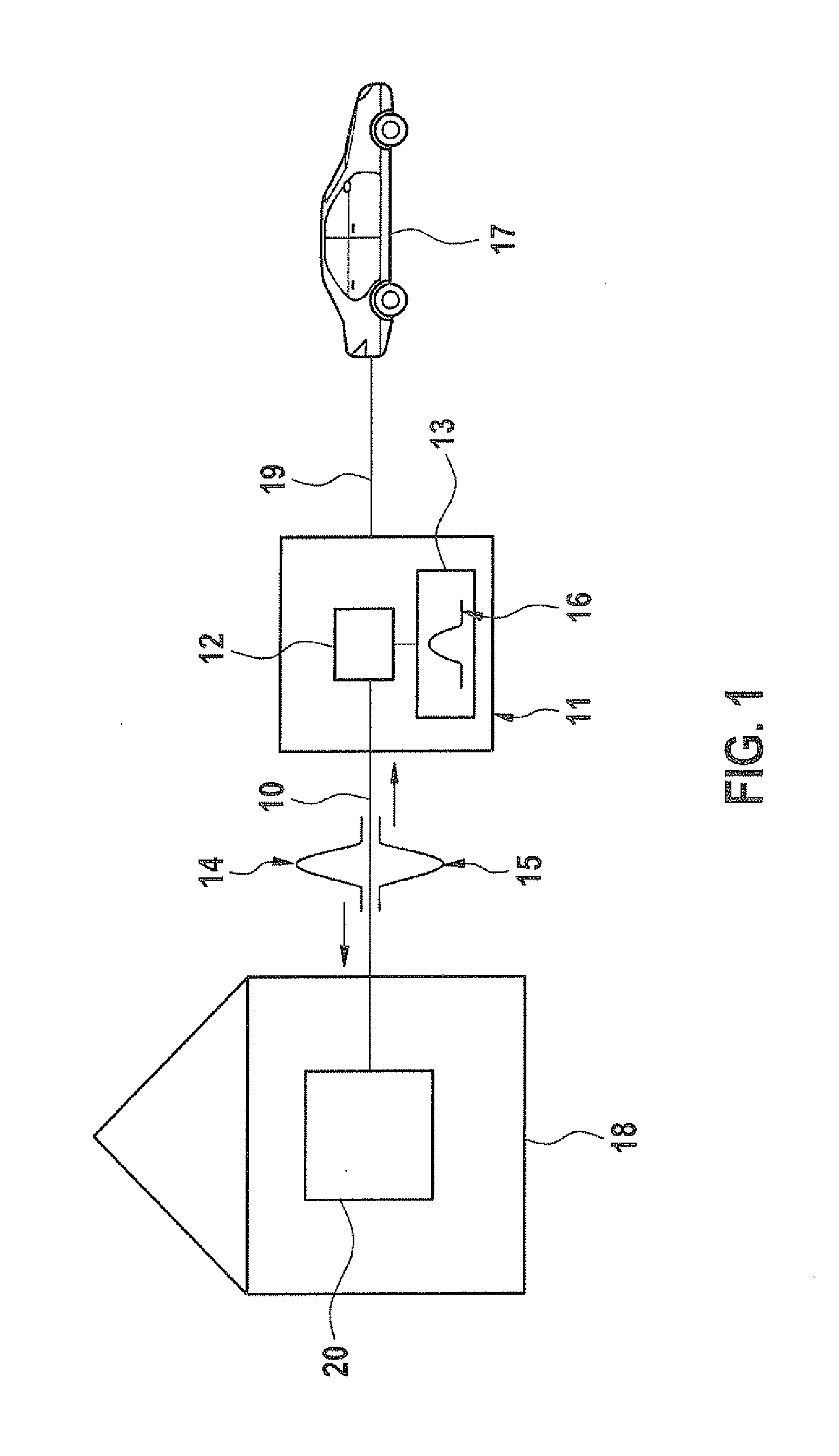
The present invention relates to a method and device for monitoring a temperature change in a charging cable. BACKGROUND INFORMATION It is believed that there are different methods for determining temperature changes in feeder cables, such as the method in US 2006/0289463 A1, for example. Knowledge of the change in temperature in feeder cables is required for the charging process of electrical vehicles, for instance. Such processes for determining temperature changes in feeder cables have the disadvantage that changes in the temperature are measured by sensors that are situated in a certain location of the feeder cable and which record the changes in temperature only at this particular location. For example, if an electrical vehicle is charged from the public power grid via the home terminal, then high charging currents are generated in the feeder cables over a longer period of time. Since homogeneous infrastructures for the private power grid do not exist and feeder cables also differ with regard to cable diameter, installation type and safeguards for the cables, for example, it is possible that at high currents in the feeder cables, locally excessive heat develops, which poses a fire and injury hazard. Furthermore, feeder cables of the public power grid are frequently installed inside the walls of buildings and thus not accessible for measurements by sensors. It is therefore believed that sensors cannot be used for detecting temperature changes at all points in the feeder cable. The method according to the present invention having the characteristic features described herein is believed to have the advantage that it allows the feeder cables of a charging device to be monitored for temperature changes and that temperature changes are detectable in all of the feeder cables. For this purpose, in a first step according to the exemplary embodiments and/or exemplary methods of the present invention, an electronics system of the charging device generates an electromagnetic input pulse, which is coupled into the feeder cable of the charging device. This input pulse is reflected at high temperature locations in the feeder cable, and the reflected portion returns to the charging device as reflected electromagnetic output pulse. In a second step, the pulse shape of the reflected electromagnetic output pulse is determined and compared to a reference pulse shape of the reflected reference pulse in a third step. The temperature change is finally ascertained in a fourth step, by comparing the output pulse shape to the reference pulse shape. If this method is employed in charging devices for charging batteries in electrical vehicles, the charging process may advantageously be carried out using the maximally possible current, without the need to take local restrictions of the home power supply network into account. The charging process is able to be performed in optimal manner, independently of the locally available infrastructure of the power supply system in the home. Advantageous further developments of the method described in herein are rendered possible by the measures delineated in the further descriptions herein. At the beginning of the charging process, the pulse shape of the reflected electromagnetic output pulse is advantageously stored in the charging device as reference pulse shape, since the temperature is low at the beginning and then rises in the course of the charging process. The reference pulse shape thus is assigned to the temperature of the feeder cable at the beginning of the charging process, which usually is the ambient temperature, and may advantageously be utilized to determine the temperature change of the current feeder cable based on the comparison of the reflected output pulse shape and the reference pulse shape. In addition, the pulse duration and pulse amplitude or the pulse spectrum obtained from a spectral analysis are advantageously used as measure for the pulse shape. Because of the temperature change in the feeder cable, the pulse shape of the electromagnetic input pulse undergoes changes after being reflected in the current feeder cable, the changes relating to the pulse duration, pulse amplitude and pulse spectrum, which are advantageously utilized as a measure for the temperature change. A first possibility for determining the temperature change in the feeder cable is a comparison of the pulse duration and/or the pulse amplitude of the reflected electromagnetic output pulse to the electromagnetic reference pulse. Another possibility for determining the temperature change in the feeder cable is a comparison of the pulse spectrum, obtained from a spectral analysis, of the reflected electromagnetic output pulse to the electromagnetic reference pulse. The electromagnetic input pulse coupled into the feeder cable in order to determine the temperature change is advantageously a low-energy pulse and has a voltage in a voltage range that is less than or equal to 30 Volt (DC). On the one hand, this ensures that the electronics system in the charging device and the electronics system situated on the feeder cable will not be damaged. On the other hand, it is ensured that the low-energy electromagnetic input pulses are able to be generated in an inexpensive and simple manner. The in-coupling of the input pulses into the feeder cable is advantageously carried out using a sequence (pattern) that varies over time and does not repeat itself within the time period required for the reflection. An electromagnetic output pulse reflected in the feeder cable is therefore able to be clearly allocated to an input pulse, coupled into the feeder cable, from which it was created as a result of the reflection in the feeder cable. Varying the chronological sequence of the input pulses advantageously provides information about the propagation times and the location of the reflection of the input pulses. If the comparison of the shape of the reflected electromagnetic output pulse with the shape of the reference pulse indicates that a defined temperature range is exceeded during the charging process, then the charging current is advantageously reduced. The fire and injury hazards during the charging operation are therefore able to be reduced. The exemplary embodiments and/or exemplary methods of the present invention will now be explained in greater detail in the following text with the aid of exemplary embodiments and the corresponding drawings. At the beginning of the charging process, the temperature in feeder cable 10 poses no fire or injury hazard attributable to overheating. The pulse shape of a first reflected electromagnetic output pulse 15 is stored in charging device 11 as reference pulse shape 16. Reference pulse shape 16 thus constitutes a reference for a reflected output pulse shape at which the temperature of the feeder cables lies in a safe range. This reference pulse shape 16 thus is assigned to the temperature of the feeder cables at the beginning of the charging process and may be used as reference scale for the output pulse shapes reflected during the charging process, so that a potential change in temperature of feeder cable 10 may be determined by comparing them to the reference pulse shape. A low-energy pulse, which has a voltage in a voltage range of less than or equal to 30 Volt, is used as electromagnetic input pulse. The incoupling of input pulses 14 may additionally take place in chronological order, so that reflected output pulse 15 arriving in charging device 11 is able to be allocated to input pulse 14 from which is was created via the reflection in feeder cable 10. The chronological sequence of coupled input pulses 14 takes the form of different patterns, which do not repeat within the time period required for the reflection. If the comparison of the pulse shapes of reflected output pulse 15 and reference pulse 16 indicates that a defined temperature range is exceeded in the charging process, then the charging current is reduced. A method for determining the temperature change of a feeder cable of a charging device in that, in a first task, the electromagnetic input pulse is coupled into the feeder cable, the electromagnetic input pulse being able to be reflected in the feeder cable and the reflected portion returning to the charging device as reflected electromagnetic output pulse; in a second task, the pulse shape of the reflected electromagnetic output pulse is determined; in a third task, the pulse shape of the reflected electromagnetic output pulse is compared to a reference pulse shape of the reflected reference pulse; in a fourth task, the temperature change is determined by comparing the two pulse shapes. 1-10. (canceled) 11. A method for determining a temperature change of a feeder cable of a charging device, which includes an electronics system for generating an electromagnetic input pulse and evaluation electronics for determining a pulse shape, the method comprising:
coupling the electromagnetic input pulse into the feeder cable, the electromagnetic input pulse being able to be reflected in the feeder cable and the reflected portion returning to the charging device as a reflected electromagnetic output pulse; determining the pulse shape of the reflected electromagnetic output pulse; comparing the pulse shape of the reflected electromagnetic output pulse to a reference pulse shape of the reflected reference pulse; and determining a temperature change from the comparison of the two pulse shapes. 12. The method of 13. The method of 14. The method of 15. The method of 16. The method of 17. The method of 18. The method of 19. The method of 20. A charging device for charging an electrical vehicle, comprising:
an electronics system for generating an electromagnetic input pulse, wherein the electromagnetic input pulse is coupled into the feeder cable, and wherein the electromagnetic input pulse is able to be reflected in the feeder cable, the reflected portion returning to the charging device as a reflected electromagnetic output pulse; and evaluation electronics for determining a pulse shape by performing the following:
determining the pulse shape of the reflected electromagnetic output pulse; comparing the pulse shape of the reflected electromagnetic output pulse to a reference pulse shape of the reflected reference pulse; and determining a temperature change from the comparison of the two pulse shapes.FIELD OF THE INVENTION
SUMMARY OF THE INVENTION
BRIEF DESCRIPTION OF THE DRAWINGS
DETAILED DESCRIPTION